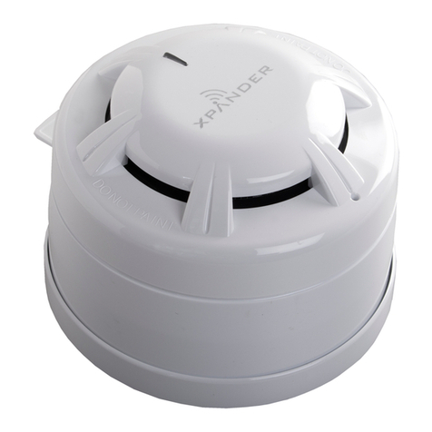
Metasys 5451 User manual

Fire Initiating Devices and Notification Appliances Technical Manual 408
Conventional Products Section
Technical Bulletin
Issue Date 1095
© 1995 Johnson Controls, Inc. 1
Code No. LIT-408134
Introduction Page 3
●
General Description 3
Installation Procedures 5
●
General Information 5
●
Base Selection and Wiring Installation Guidelines 5
●
Installation 7
●
Tamper-Proof Feature 8
Testing and Maintenance Procedures 9
●
Testing 9
●
Maintenance 11
●
Limitations 12
5451 Conventional Plug-In Rate-of-Rise Heat Detector

2 Conventional Products—5451 Conventional Plug-In Rate-of-Rise Heat Detector

Conventional Products—5451 Conventional Plug-In Rate-of-Rise Heat Detector 3
Introduction
This document contains important information about installing and
operating the 5451 conventional, contact-type, rate-of-rise, heat detectors.
These conventional, contact-type detectors are manufactured by System
Sensor for use with Johnson Controls systems. If you install this detector
for someone else to use, leave a copy of this document with the user.
This detector must be installed in compliance with the control panel
installation manual and meet the requirements of the authority having
jurisdiction. The National Fire Protection Association (NFPA) has
published codes, standards, and recommended practices for the installation
and use of detectors.
Before you install any rate-of-rise heat detectors, read and be familiar
with:
●the control panel system installation manual
●the requirements of the authority having jurisdiction
●NFPA-72-National Fire Alarm Code, national codes, local codes, and
any special requirements of the authority having jurisdiction
●or, for non-United States installations, applicable codes and standards
specific to country and locality of installation
●System Sensor
in the Fire Initiating Devices and Notification Appliances Technical
Manual (FAN 408), which provides detailed information on detector
spacing, placement, zoning, wiring, and special applications
!
CAUTION: Equipment hazard. Do not use in potentially
explosive atmospheres. Do not leave unused wires
exposed.
Model 5451 is a conventional, contact-type, rate-of-rise with fixed
temperature alarm heat detector utilizing a state-of-the-art dual thermistor
sensing circuit. These detectors are designed to provide open area
protection with 50 foot (1,5240 mm) spacing capability and are to be used
with compatible control panels only.
Two Light Emitting Diodes (LEDs) on each detector provide 360°
visibility of the detector indication when the detector is powered and when
it is in alarm (Figure 3).
General
Description

4 Conventional Products—5451 Conventional Plug-In Rate-of-Rise Heat Detector
The detector also has provision for the connection of an optional model
RA400Z remote annunciator. The RA400Z provides a visual indication of
an alarm in the connected detector, and mounts to a single gang box.
Table 1: Specifications Summary
Specifications
Diameter 4.1 inches (104 mm)
Height 2.1 inches (53 mm)
Weight 5 ounces (150 gm)
Installation Temperatures 32 to 100°F (0 to 38°C)
Operating Humidity Range 10 to 93%, Relative Humidity
Latching Alarm Reset by momentary power interruption
Sensitivity 135°F (57°C) Fixed or 15°F/min rate-of-rise
Standby Current 100 µA maximum
Electrical Ratings
Minimum Standby Voltage 8.5 VDC
Maximum Standby Voltage 35 VDC
Minimum Voltage Required to Operate an
Accessory 4.20 VDC
Maximum Standby Current 0.12 mA
Maximum Equivalent Capacitance 0.00002 mF
Maximum Ripple 4000 m VAC
Maximum Startup Time 34 Seconds
Minimum Alarm Current 10 mA
Maximum Alarm Current 100 mA
Minimum Reset Voltage 2.50
Maximum Reset Time 0.30 Seconds
Accessories
Flanged Base B401B
Additional Bases B402B, B404B, B406B
Remote Annunciator RA400Z
Field Sensitivity Test MOD400R
Replacement Test Magnet M02-04-00
Retrofit Replacement Flange F110
Replacement Dust Cover Dust 12
Recess Mounting Kit
(for use with B401, B401R) RMK400
Surface Mounting Kit
(for use with B401, B401R) SMK400
End-of-Line Relay for Power Supervision A77-716B

Conventional Products—5451 Conventional Plug-In Rate-of-Rise Heat Detector 5
Installation Procedures
This section contains installation information for the 5451 plug-in
rate-of-rise heat detector. Instructions are given for wiring and installing
the detector.
Refer to the plug-in detector bases technical bulletins in the Fire Initiating
Devices and Notification Appliances Technical Manual (FAN 408) for
base selection and wiring instructions.
Note: All wiring must conform to the National Electrical Code, all
applicable local codes, ordinances, and regulations, using the
proper wire size. Verify all detector bases are installed, the
initiating device circuits have been tested, and the wiring
is correct.
System Sensor has a variety of plug-in detector bases:
●2-wire applications with and without relays and/or current limiting
resistors
●4-wire 24 VDC or 120 VAC applications
All bases are provided with screw terminals for power, ground, remote
annunciator connections, and relay contact connections. The electrical
ratings for each detector-base combination are included in the base
technical bulletins.
Table 2: Bases Used with the 5451
Model
Number Version Loop
Type Current
Limit
Resistor
Alarm
Contact
Type
Nominal
Voltage Current
Draw on
Alarm
(mA)
B401B UL/ULC 2-wire* No — 12/24
VDC 10-100**
B402B UL/ULC 4-wire Yes Form-A and
Form-C 24 VDC 14-39
B404B UL/ULC 4-wire Yes Form-A,
Form-C,
and Form-A
Supervisory
120 VAC 75 mA AC
Max.
B406B UL/ULC/
EN-54 2-wire* No Form-C 24 VDC 12-100**
* Functionality contingent on panel compatibility.
** Must be limited by control panel.
General
Information
Base Selection
and Wiring
Installation
Guidelines

6 Conventional Products—5451 Conventional Plug-In Rate-of-Rise Heat Detector
The conductors used to connect smoke detectors to control panels and
accessory devices should be color-coded to reduce the likelihood of wiring
errors, and should comply with the type of wiring recommended in the
control panel’s technical manual. Incorrect connections can prevent a
system from responding properly in the event of a fire.
Note: Refer to the releasing device manufacturer’s installation instruction
for proper connections.
For Initiating Device Circuit (IDC) wiring (the wiring between
interconnected detectors), it is recommended that the wire be no smaller
than 18 American Wire Gauge (AWG) (1.0 square mm). However, the
screws and clamping plate can accommodate wire sizes up to 12 AWG
(3.3 square mm). For best system performance, the power (+) and (–)
wires should be twisted pair and installed in separate grounded conduit to
protect the IDC from other types of circuits in the system.
Smoke detectors and alarm system control panels have specifications for
allowable IDC resistance. Consult the control panel manufacturer’s
specifications for the total IDC resistance allowed for the control panel
being used before wiring the detector IDCs.
Begin electrical connections by stripping about 3/8 inch insulation from
the end of the wire (use strip gauge molded in detector base). Then, slide
the bare end of the wire under the clamping plate and tighten the clamping
plate screw.
Note: Break the wire at each terminal to ensure that the connections are
supervised--do not loop the wire under the terminals.
This Not This
wirguide
Figure 1: Electrical Connections
Contacts are shown in standby mode and will transfer in alarm condition.
The detectors are marked with a compatibility identifier located as the last
digit of a five digit code stamped on the back of the product. Connect
detectors only to compatible control units as indicated in the Device
Compatibility Technical Bulletin in the Fire Management Accessories
Manual (FAN 445).

Conventional Products—5451 Conventional Plug-In Rate-of-Rise Heat Detector 7
!
WARNING: Shock hazard. Disconnect power from the
Initiating Device Circuits (IDC) before installing
detectors.
1. Insert the detector into the detector base.
2. Turn the detector clockwise until the detector drops into place.
3. Continue turning detector clockwise to lock it in place.
4. Enable the tamper-proof feature, if used. For instructions see the
Tamper-Proof Feature section of this technical bulletin.
5. After all detectors have been installed, apply power to the control unit.
6. Test the detector using the magnet as described in the Testing section
of this technical bulletin.
7. Reset the detector at the system control panel.
8. Notify the proper authorities that the system is in operation.
Installation
Installing the
5451

8 Conventional Products—5451 Conventional Plug-In Rate-of-Rise Heat Detector
This detector includes a tamper-proof feature that prevents removal of the
detector without the use of a tool.
To make the detector tamper-proof:
1. Break off the smaller tab at the scribed line on the tamper-proof tab on
the detector mounting bracket.
2. Install the detector.
tm prprf
Plastic Lever
Break tab at
dotted line b
y
twistin
g
toward
center of base.
Figure 2: Activating the Tamper-Proof Feature
To remove the detector from the bracket once it has been made
tamper-proof:
1. Use a pocket screwdriver, or similar tool, and depress the
tamper-proof tab located in the slot on the mounting bracket.
2. Turn the detector counterclockwise until it separates from the base.
See the applicable detector base data for the location of the tamper-proof
break-off tab and the location of the tool insertion point.
After the detector has been made tamper-proof, head removal first requires
removal of the decorative ring.
remdetct
Use sm all-bladed
screwdriver to
push plastic lever
in direction of arrow.
Figure 3: Removing the Detector Head from the Base
The tamper-proof feature may be defeated by breaking and removing
the plastic lever from the base. However, this prevents using the
feature again.
Tamper-Proof
Feature

Conventional Products—5451 Conventional Plug-In Rate-of-Rise Heat Detector 9
Testing and Maintenance
Procedures
Before testing, notify the proper authorities that the smoke detection
system will be temporarily out of service while undergoing testing and
maintenance. Disable the zone, IDC, or system undergoing maintenance
to prevent unwanted alarms.
After a detector is set into alarm by one of the following test methods and
the alarm activating device is removed from the detector, the system
should be reset at the control panel before testing any additional detectors.
After testing is complete and the system is returned to its normal
configuration, notify the proper authorities that the system is again in
service.
All detectors must be tested after installation and following periodic
maintenance. Testing methods must satisfy the authority having
jurisdiction. Detectors offer maximum performance when they are tested
and maintained in compliance with National Fire Protection Association
(NFPA) 72-National Fire Alarm Code.
Before testing the detector, check to ensure that the LEDs are blinking. If
they are not, the detector has lost power (check the wiring) or it is
defective (replace or return for repair).
Test Magnet (M02-04-00)
1. Position the magnet against the cover opposite the test module socket
(Figure 2).
2. The LEDs on the detector should light within 30 seconds, and the
alarm should be reported at the control panel. If the LEDs fail to
light, check the power to the detector and the wiring in the detector
base.
3. Reset the detector at the system control panel.
Testing
Testing the 5451

10 Conventional Products—5451 Conventional Plug-In Rate-of-Rise Heat Detector
testswc6
LED
Test Module
Socket
TestMa
g
net.....
Painted
Surface
LED
Test
Magnet
Figure 4: Bottom and Side Views Showing
Position of Test Magnet
Calibrated Sensitivity Test (MOD400 or MOD400R)
The MOD400 or MOD400R is used with a Digital Multimeter (DMM) or
voltmeter to check the detector sensitivity as described in the module’s
manual.
If the detector’s sensitivity limits or the MOD400R limits do not appear on
the back of the detector, the MOD400R is not suitable for field sensitivity
testing of that unit.
Direct Heat Method (Hair Dryer of 1000 - 1500 watts)
1. From the side of the detector, direct the heat toward the detector.
Hold the heat source about 12 inches away to prevent damage to the
cover during testing.
If a detector goes into alarm, it will reset only if the detector has
cooled and if its power is momentarily interrupted.
2. Check the control panel being used to determine whether the RESET
switch (or some other auxiliary device or control) momentarily cuts
off power to the detector circuit.
Detectors that fail these tests should be cleaned as described in the
Maintenance section of this technical bulletin and retested. If the detectors
still fail these tests, they should be replaced or returned for repair.

Conventional Products—5451 Conventional Plug-In Rate-of-Rise Heat Detector 11
Before cleaning, notify the proper authorities that the system is undergoing
maintenance and will be temporarily out of service. Disable the IDC zone
or system undergoing maintenance to prevent unwanted alarms.
After maintenance and testing is complete and the system is returned to its
normal configuration, notify the proper authorities that the system is again
in service.
The 5451 detector has been designed to be as maintenance-free as
possible. Normal air-borne dust, however, can accumulate on the
detector’s sensing elements and cause them to become less sensitive. All
detectors should be tested and cleaned at least once a year, and those in
dustier areas should be tested and cleaned more often. Detectors must also
be cleaned and tested immediately after a fire.
1. Remove detector from mounting base.
2. Use a vacuum cleaner to remove dust from the sensing chamber.
3. Reinstall the detector.
4. Test the detector as described in the Testing section of this technical
bulletin.
Maintenance
Cleaning the 5451

12 Conventional Products—5451 Conventional Plug-In Rate-of-Rise Heat Detector
●Heat detectors are designed to protect property, not life. They do not
provide early warning of fire and cannot detect smoke, gas,
combustion particles, or flame. They alarm when temperatures at the
heat detector reach 135°F (57°C). The detector can also alarm on a
rate-of-rise. Given the rapid growth of certain types of fires, heat
detectors cannot be expected to provide adequate warning of fires
resulting from smoking in bed, inadequate fire protection practices,
violent explosions, escaping gas, improper storage of flammable
liquids like cleaning solvents, other safety hazards, or arson.
●Heat detectors do not always detect fires because the fire may be a
slow, smoldering low heat type (producing smoke), because they may
not be near where the fire occurs, or the heat of the fire may bypass
them. Heat detectors will not detect smoke, gas, flames, or
combustion particles.
●Heat detectors are components in professionally installed fire alarm
systems. They will not function if they have been improperly wired
into the fire alarm system or if power to them is cut off for any reason.
●Heat detectors cannot last forever. They should be tested and
maintained following the instructions in this manual. To be safe, they
should be replaced after they have been installed for 15 years.
●Refer to the NFPA 72-National Fire Alarm Code for application, or,
for non-United States installations, applicable codes and standards
specific to country and locality of installation.
Limitations
Controls Group FAN 408
507 E. Michigan Street Fire Initiating Devices and Notification Appliances Technical Manual
P.O. Box 423 Printed in U.S.A.
Milwaukee, WI 53201
Table of contents
Other Metasys Security Sensor manuals
Popular Security Sensor manuals by other brands

PCB Piezotronics
PCB Piezotronics ICP M260A01 Installation and operating manual

ADEMCO
ADEMCO 1875EX installation instructions
DMP Electronics
DMP Electronics 1166 installation guide

Robertshaw
Robertshaw 365A instruction manual
AVS Electronics
AVS Electronics WIC 4 manual
SUREN
SUREN CPL-1312 Installation, operation and specification manual
