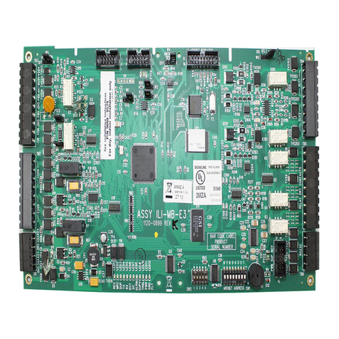
Metasys IFC-1010 User manual

IFC-1010/2020 Technical Manual 448
Programming Section
Technical Bulletin
Issue Date 0701
© 2001 Johnson Controls, Inc. 1
Code No. LIT-448060 www.johnsoncontrols.com
Introduction Page 5
•Location of Content Changes 5
•Supported Products *5
•Menus 6
•Passwords 6
•Backspace Key *6
•About Transponder Rapid All Call *7
•About SIB-NET *7
Initial Programming Outline *9
Main Programming 11
•Partial System Programming *13
•LIB Installation *16
•LIB SLC Loop Style *17
•Time Delays 18
•Power Supplies *19
•Zone Boundary *20
•External Equipment *21
•Local Parameters *25
•General Operation of the Piezo Sounder 27
•Local Mode Operation 28
•Extended Local Mode Operation *28
•NFPA Listings *29
•Pre-Alarm Function 30
IFC-1010/2020 Programming
*Indicates those sections where changes have occurred since the last printing.

2 Programming—IFC-1010/2020 Programming
•Intelligent Serial Interface Board Programming Page 31
•1=INSTL - ISIB Installation 33
•2=ANN - Annunciator Installation *33
•3=XINT - External Interface Parameters 34
•4=DACT - UDACT Installation *35
•Additional System Parameters *36
•Full System Programming *40
•Partial Point Programming *42
•Type ID *45
•Control-By- Event *46
•Label *47
•Optional Features *48
•Annunciator Mapping *50
•Cooperative Control-By- Event 52
•Full Point Programming *53
•Remove *57
•Password 58
•Message 59
•History Mode 59
Alter Status Menu *63
•Disable Point *65
•Control Module *65
•Detector Sensitivity *66
•Time 66
•Diagnostics 67
•Walk Test *68
•Walk Test Reports *70
•Group Zone Disable *73
*Indicates those sections where changes have occurred since the last printing.

Programming—IFC-1010/2020 Programming 3
Software Type IDs Page 75
•Group 1 *76
•Group 2 *77
•Group 3 *78
•Group 4 *79
•Group 5 *80
•Group 6 *81
•Group 7 *81
•Group 8 82
•Group 9 82
•Group 10 82
•Group 11 82
•Group 12 82
•Group 13 *83
•Group 14 *83
•Group 15 83
•Group 16 *83
•Group 17 84
•Group 18 84
Control-By-Event Programming 85
•Introduction *85
•Operators *87
•Size Limitations *91
•Cooperative Control-By-Event 93
•Null Control-By- Event 94
•Programming Examples 95
Dual Stage Alert/Evacuation *99
Application and Clarification Notes *101
•Note 27: System Scanning Order 104
*Indicates those sections where changes have occurred since the last printing.

4 Programming—IFC-1010/2020 Programming

Programming—IFC-1010/2020 Programming 5
Introduction
This document covers the programming options of the IFC-1010/2020
Combination Fire/Security Protective Signaling System and the features
available to the operator. This document is presented from the perspective
of the Cathode Ray Tube (CRT-2) monitor. The prompts are displayed on
the CRT-2 screen in the order they appear (top to bottom) on the pages
that follow. For programming the control panel from the built-in keypad,
an overview of the panel’s Display Interface Assembly (DIA-2020 or
DIA-1010) is illustrated in the IFC-1010/2020 Operations Technical
Bulletin (LIT-448100). For CRT installation information, refer to
Installing the IFC-1010/2020 Technical Bulletin (LIT-448155).
The product this document supports is Underwriters Laboratories Inc.®
(UL) Multiple Listed, which requires that the content of the documentation
inherited from the manufacturer remain intact. Minor changes clarify
information such as vendor-specific product names and literature names
and numbers. More significant changes to the original technical content,
such as additions or corrections, are identified with Note Numbers Nx.
For the Note Numbers content, refer to the Application and Clarification
Notes section at the end of this document.
This document may contain references to some features that are not
supported before MetasysRelease 9.01 and IFC-1010/2020 Merge M2.8
firmware. If you are using earlier firmware releases, please ignore
references to the following products:
•NAM-232
•LIB-200A
•LIB-400
•SIB-2048A
Also, the AVPS-24 and AVPS-24E have been replaced by the APS-6R.N25
Location of
Content
Changes
Supported
Products

6 Programming—IFC-1010/2020 Programming
At the top of each submenu in this programming guide, a string of keys
illustrates the sequence of keys you press to reach a particular menu.
For example:
Prog !
1
????
Level 2 Password
Or
Selecting Programming Mode Select Partial Point
Programming.
Select Message option to
change custom user label.
&
7
intro1
Figure 1: Sample Key Sequence to Access a Menu
Access to menu levels one and two require entry of specific passwords.
These levels allow an authorized programmer to initialize or alter the
programming of the IFC-1010/2020. Level One and Level Two entry
requirements are defined as follows:
●Alter Status Level One password required.
●Programming Level Two password required.
If the main operator of the system requires access to a function that is
password protected, contact the local Johnson Controls office that installed
the system for the required passwords. The IFC-2020 and IFC-1010 are
shipped with initial Level One and Level Two passwords of five zeroes
(00000).
Note: Unacknowledged points must be acknowledged prior to being
reprogrammed.
The Backspace key serves several purposes.
Backspace
Backspace
Figure 2: Backspace Key
At a menu prompt, the Backspace key aborts the selection of that option:
ENTER 40 CHARACTER USER LABEL:
When entering data, the Backspace key erases the last character or digit
entered:
ENTER 40 CHARACTER USER LABEL: JOHNSON CONTROLS
Menus
Passwords
Backspace Key

Programming—IFC-1010/2020 Programming 7
At certain points during operator or programming functions, the
Backspace key aborts all the data just entered. For instance, during Full
Point Programming, a particular point must be fully programmed before
the control panel can use the information. If the Backspace key is pressed
at a prompt (:) before all parameters (such as address, Type Identification
[ID], Control-By-Event ([CBE] interlock equation, etc.) for that point are
entered into the control panel, then all previous entries for that point will
be ignored.
When the All Call button is pressed on an Audio Message Generator
(AMG) connected to an IFC-1010/2020 panel, an All Call activation
signal is received by the panel. Upon receipt of the All Call signal, the
IFC-1010/2020 panel immediately activates all specially programmed
XP Transponder and addressable control module circuits, which have been
programmed with a Software Type ID SPKR. Programming is performed
in the XP Transponder using the XRAM-1 (see the XP Transponder
Technical Bulletin [LIT-448180]).
The SIB-2048(A), SIB-N2, and SIB-NET serial communications boards
are available for use on the IFC-1010/2020 system (see the Installing the
IFC-1010/2020 Technical Bulletin [LIT-448155]). For the IFC-1010/2020
with the Metasys Fire Network system, only the SIB-NET may be used. If
a SIB-NET board is not installed, specific Fire Network functions cannot
be programmed or viewed under Read Status.
About
Transponder
Rapid All Call
About SIB-NET

8 Programming—IFC-1010/2020 Programming

Programming—IFC-1010/2020 Programming 9
Initial Programming Outline
For initial programming of the IFC-1010/2020, or for major changes and
additions, the following basic procedure is recommended to prevent errors
resulting in reprogramming and wasted time.
1. Make copies of the Program Worksheets in the Programming
Worksheets Technical Bulletin (LIT-448070).
2. Use these worksheets to record the exact information for every
detector, module, annunciator point, and software zone in the system.
Pay special attention to the Software Type IDs listed in the Software
Type IDs section of this document. For voice systems, pay close
attention to AMG annunciator point commands as described in the
IFC-1010/2020 Installing the Fire Fighters Command Center
Technical Bulletin (LIT-448165).
3. If a CRT is to be used, configure it as described in the Installing the
IFC-1010/2020 Technical Bulletin (LIT-448155).
4. Assemble and apply power to the control panel as described in the
Installing the IFC-1010/2020 Technical Bulletin (LIT-448155). All
system boards (including all Loop Interface Boards [LIBs]) must be
physically installed.
5. Change the Level One and Level Two passwords as necessary. The
IFC-1010/2020 is delivered from the factory with passwords of
00000. Write down or memorize your passwords. To change the
passwords, enter the following:
Prog )
0
)
0
)
0
)
0
!
1
)
0
@
2
^
6
Initpo1
Or
Figure 3: Key Sequence to Change Passwords
If the control panel is to be programmed before installation of LIB
Signaling Line Circuit (SLC) addressable devices, the panel exits
programming and sounds the piezo when each programmed device is not
detected. To avoid the piezo from sounding, use the following key
sequence (after entering the password):

10 Programming—IFC-1010/2020 Programming
!
1
&
7
Y Y Y Backspace
Initpo2
Figure 4: Key Sequence to Avoid Piezo Sounding
When the first device has been programmed into the system, the
control panel reports a trouble condition and will exit Programming
mode.
IMPORTANT: Do not acknowledge this trouble.
Reenter programming and the control panel will no longer exit
programming or sound the piezo for subsequent trouble conditions. N1
Continue in the programming mode.
•For initial system programming, read the Full System Programming
section in this document and answer all the questions in that section
before entering programming mode. Then, enter Full System
Programming and load all the answers into the control panel.
•Enter Full Point Programming. Use the worksheets developed in the
second step of this outline and enter information on all points in the
system. Program points in the following order:
1. annunciator points
2. zones
3. detector points
4. module points
•When devising Control-By-Event (CBE) equations for a particular
device, remember that the label of the first software zone in the
equation of each addressable initiating device appears on the panel
display, along with the label of the device, when an alarm condition
occurs. For more information, see the Label (LBL) option in the
Label section in this document.
•Enter the System Message.
•Install all devices and thoroughly test the entire system. Use the Walk
Test feature to test devices and their programming.
•Make a hard copy record of the program on the printer.
If desired, upload the program to store on an external device (computer
hard drive or floppy) using the FIRE PRO or the VeriFireprogramming
utility.

Programming—IFC-1010/2020 Programming 11
Main Programming
Access the Programming mode by entering the following (the Level Two
password is required):
Prog ????
Level 2 Password
Mainpro1
Figure 5: Key Sequence to Access Programming Mode
After entering the Programming mode, the Main Programming menu
displays:
PRESS 1=PSYS,2=FSYS,3=PPRG,4=FPRG,5=REMV,6=PSWD,7=MSG,8=HIS:
The Main Programming menu has eight options, including:
Table 1: Main Programming Menu Options
Main
Programming
Menu Option
Description
1=PSYS Partial System Programming
Selective programming of system-wide functions (such as number of LIBs, APS-6R,
ISIB [Intelligent Serial Interface Board], Signal-Silence Inhibit and Signal Cut-Out, Alarm
Verification, and number of annunciator modules).
2=FSYS Full System Programming
Complete programming of system-wide functions (such as number of LIBs, APS-6R, ISIB,
Signal-Silence Inhibit and Signal Cut-Out, Alarm Verification, and number of annunciator
modules).
3=PPRG Partial Point Programming
Selectively altering the operating parameters of LIB SLC addressable devices,
software-defined zones, and annunciator points.
4=FPRG Full Point Programming
Complete programming of addressable LIB SLC devices, software-defined zones, annunciator
points, and their respective operating parameters.
5=REMV Remove
Permits the selective removal (from control panel memory) of any of the system’s addressable
SLC devices, software-defined zones, or annunciator points.
6=PSWD Password
Allows the programmer to assign custom 5-digit Level One and Level Two passwords.
7=MSG Message
Allows the Level Two programmer to define the custom 40 character user label displayed on
the CRT monitor and the panel’s Liquid Crystal Display (LCD).
8=HIS History
Allows the programmer to enable or disable storage of events and the clearing of stored
events.

12 Programming—IFC-1010/2020 Programming
The Main Programming menu flowchart is located in Figure 6. Detailed
information on the Main Programming options follows.
Press key.
PROG
Enter Level 2
password.
Valid
Password?
Yes
Select Main
Programming Menu
Option 1-8.
No Error Message
1 = PSYS
(Partial System Programming)
2 = FSYS
(Full System Programming)
3 = PPRG
(Partial Point Programming)
4 = FPRG
(Full Point Programming)
5 = REMV
(Selective Removal of
Devices, Zones, etc.)
6 = PSWD
(Assign or alter passwords.)
7 = MSG
(Assign or alter message
displayed on control panel.)
8 = HIS
(Enable, disable, or clear
history buffer.)
Mainprfc
Figure 6: Main Programming Menu Flowchart

Programming—IFC-1010/2020 Programming 13
Prog !
1
????
Level 2 Password
Sec11a
Figure 7: Key Sequence to Change System Functions
Option 1 from the Main Programming menu allows the programmer to
change the programming of system-wide functions such as Alarm
Verification of detectors, Signal-Silence Inhibit, Signal Cut-Out, disabling
the piezo sounder, enabling Rapid Polling, and enabling supervision of
peripheral equipment in the system. Additional system parameters, such as
the number of AVP-6Rs, LIBs, annunciators, and Intelligent Serial
Interface Boards (ISIB) in the system can be adjusted. The LIB SLC loops
N2 can also be changed in Partial System Programming.
After selecting Option 1 from the Main Programming menu, the display
will show the Partial System Programming submenu:
PRESS 1=INST,2=STY,3=TDLY,4=AVPS,5=ZBND,6=EXTEQ,7=LOCP,8=ISIB,9=PARM :
Note: Submenu Option 4 includes APS-6R as well as AVPS-24 power
supplies.
The Partial System Programming submenu has nine options listed in
Table 2.
Partial System
Programming
1=PSYS

14 Programming—IFC-1010/2020 Programming
Table 2: Partial System Programming Submenu
Partial System
Programming
Submenu
Description
1=INST Installation
Installation or removal of the SLC loop interface boards from memory.
2=STY Style
Changing (in memory) the National Fire Protection Association (NFPA) style of the SLC
loops.
3=TDLY Time Delays
Setting the time delays for Alarm Verification, Signal-Silence Inhibit, and Signal Cut-Out.
4=AVPS Audio/Visual Power Supplies
Telling the IFC-1010/2020 how many Audio/Visual Power Supplies are installed in the
system. The AVPS-24 and AVPS-24E have been replaced by the APS-6R.
5=ZBND Zone Boundary
Setting the zone boundary for the software memory map.
6=EXTEQ External Equipment
Changing the external equipment options, such as electrical supervision of the CRT monitor.
7=LOCP Local Parameters
Setting local parameters, such as enabling or disabling the piezo sounder during point
programming of SLC loop devices, LIB Local mode, and NFPA programming.
8=ISIB Intelligent Serial Interface Board
Installation or removal of the Intelligent Serial Interface Board (SIB-2048[A], SIB-N2, or
SIB-NET) or annunciator modules (for a description of annunciator modules, refer to the
Serial Communications section of the IFC-1010/2020 Installation Technical Bulletin
[LIT-448155]). Also used to enable the external interface for upload/download, and Universal
Digital Alarm Communicator Transmitter (4=DACT – UDACT Installation) selection.
9=PARM Additional System Parameters
Selection of additional system parameters such as the detector day/night sensitivity settings
and rapid polling.
See Figure 8 for the Partial System Programming menu flowchart.
Detailed information on the Partial System Programming options follows.
Notes: When removing loop interface boards, all installed points on the
affected LIBs are automatically removed upon cycling power to the
system. Store programming information for installed points in a
FIRE PRO or VeriFire database prior to removal of the LIB. Using
the FIRE PRO or VeriFire application for the reprogramming of
previously removed points is highly recommended.
When removing annunciator modules, all installed points on the
affected annunciators must be removed first for proper system
operation.

Programming—IFC-1010/2020 Programming 15
Select Partial System
Programming Submenu
Option 1-9.
1 = INST
(Install/remove loop
interface boards.)
2 = STY
(Choose NFPA style
for SLC loops.)
3 = TDLY
(Setting of Alarm Verification,
Signal Silence, etc.)
4 = AVPS
(Program number of supplies
for system.)
5 = ZBND
(Set the boundary for
software memory map.)
6 = EXTEQ
(Select options for CRT
monitor and/or printer.)
7 = LOCP
(Enable/disable piezo sounder,
LIB local mode, and
NFPA programming.)
8 = ISIB
(Install/remove ISIB.)
9 = PARM
(Day/night Sensitivity
Settings, etc.)
Psysprf
1=PSYS
Figure 8: Partial System Programming Submenu Flowchart

16 Programming—IFC-1010/2020 Programming
Prog !
1
!
1
????
Level 2 Password
Sec11aa
Figure 9: Key Sequence to Install an LIB
Select Option 1 from the Partial System Programming submenu to install
or remove LIB SLC loops from memory. The LIB boards still must be
physically installed or removed from the system to prevent a system
trouble condition. The Install Option flowchart is located in Figure 11. The
LIB capability is as follows:
•The IFC-2020 is capable of a maximum of ten LIBs (1980 devices
total in the system).
•The IFC-1010 is capable of a maximum of four LIBs (792 N18 SLC
devices total in the system).
The following programming example illustrates the installation of Loop
Interface Board (LIB) Number 3.
PRESS 1=INST,2=STY,3=TDLY,4=AVPS,5=ZBND,6=EXTEQ,7=LOCP,8=ISIB,9=PARM : 1
ENTER THE LIB BOARD NUMBER TO CHANGE (1 - 10) : 3
IS LIB BOARD03 TO BE INSTALLED IN SYSTEM? (Y=YES,N=NO) : Y
ENTER THE STYLE OF SLC LOOP 03 (6 OR 4) : 6
DO YOU WANT TO CHANGE ANOTHER LIB BOARD? (Y=YES,N=NO) : N
PROGRAMMING COMPLETE - POWER DOWN TO MAKE APPROPRIATE CHANGES
For information on LIB-400 and its correct slot address, refer to the
Installing the IFC-1010/2020 Technical Bulletin (LIT-448155). See notes
in the Partial System Programming section of this document.
LIB Installation
1=INST

Programming—IFC-1010/2020 Programming 17
Prog !
1
@
2
????
Level 2 Password
sec112a
Figure 10: Key Sequence to Change the LIB SLC Style
Option 2 from the Partial System Programming submenu allows the
programmer to change in IFC-1010/2020 memory the NFPA Style for the
Signaling Line Circuit (SLC) loop connected to each LIB. The SLC loop
must be field wired in accordance with the Style set in memory (see the
Installing the IFC-1010/2020 Technical Bulletin [LIT-448155]). Refer to
Figure 12 for the Style Option flowchart.
The following programming example illustrates setting SLC Loop 5 as an
NFPA Style 6 circuit. The CRT screen prompts are displayed in the
priority that they appear (top to bottom).
PRESS 1=INST,2=STY,3=TDLY,4=AVPS,5=ZBND,6=EXTEQ,7=LOCP,8=ISIB,9=PARM: 2
ENTER THE SLC LOOP NUMBER TO CHANGE (1 - 10) : 5
ENTER THE STYLE OF SLC LOOP 05 (6 OR 4) : 6
DO YOU WANT TO CHANGE ANOTHER SLC LOOP? (Y=YES,N=N0) : N
1 = INST
Enter LIB Board
number (1-10).
Install/remove
LIB selected.
Enter style of
SLC loop.
Change
another LIB?
Yes
Instopfc
No
(Exit Prog Mode)
Figure 11: Install Option Flowchart
2 = STY
Enter loop number. Enter NFPA style
for loop (6 or 4).
Change
another Style?
Yes
Styopfc
No
(Exit Prog Mode)
Figure 12: Style Option Flowchart
LIB SLC Loop
Style
2=STY

18 Programming—IFC-1010/2020 Programming
Option 3 from the Partial System Programming submenu allows the
programmer to enable/disable Alarm Verification of detectors,
Signal-Silence Inhibit, and Signal Cut-Out for control modules, as well as
set the appropriate time delays for these functions. For a full description of
these functions, see the Glossary Technical Bulletin (LIT-448700).
Yes Yes
Yes
Enter detector
verification time
(5-50 seconds).
No No
No
Yes Yes
Yes
No No
(Exit Program Mode)
Change
detector
verification
time?
Enable
detector
verification
time?
Change
Signal Silence
Inhibit
time?
Enable
Signal Silence
Inhibit
time?
Change
Signal Cut-Out
time?
Tdelopfc
Enable
Signal Cut-Out
time?
Enter Signal
Cut-Out time
(1-2040 seconds).
Enter Signal
Silence Inhibit
time
(1-255 seconds).
3=TDLY
Figure 13: Flowchart of Time Delay Option (3=TDLY)
The following programming example illustrates enabling all
three functions:
PRESS 1=INST,2=STY,3=TDLY,4=AVPS,5=ZBND,6=EXTEQ,7=LOCP,8=ISIB,9=PARM : 3
DO YOU WANT TO CHANGE THE DETECTOR VERIFICATION TIME? (Y=YES,N=NO) : Y
DO YOU WANT THE DETECTOR VERIFICATION TIME ENABLED? (Y=YES,N=NO) : Y
ENTER THE DETECTOR VERIFICATION TIME(5-50 IN 1 SECOND INCREMENTS) : 35
DO YOU WANT TO CHANGE THE SIGNAL SILENCE INHIBIT TIME? (Y=YES,N=NO) : Y
DO YOU WANT THE SIGNAL SILENCE INHIBIT TIME ENABLED? (Y=YES,N=NO) : Y
ENTER THE SIGNAL SILENCE INHIBIT TIME (1-255 IN 1 SECOND INCREMENTS) : 240
DO YOU WANT TO CHANGE THE SIGNAL CUT-OUT TIME? (Y=YES,N=NO) : Y
DO YOU WANT THE SIGNAL CUT-OUT TIME ENABLED? (Y=YES,N=NO) : Y
ENTER THE SIGNAL CUT-OUT TIME (1-2040 IN 1 SECOND INCREMENTS) : 600
Time Delays
3=TDLY

Programming—IFC-1010/2020 Programming 19
General Considerations
The capability of the control panel to provide the functions of Alarm
Verification, Signal Cut-Out, and Signal-Silence Inhibit can be
enabled/disabled by the programmer in both Full and Partial System
Programming. However, to make use of these functions, the Signal Silence
option (for silenceable control modules) and the Alarm Verification option
(for addressable detectors) still must be enabled/disabled individually for
each SLC addressable device under Full or Partial Point Programming.
For instance, when programming Alarm Verification:
•Under Full or Partial System Programming, the programmer turns
Alarm Verification On and sets the verification time period.
•Under Full or Partial Point Programming, the programmer individually
selects Alarm Verification for each detector:
- Detector 1 = Yes
- Detector 2 = No
- Detector 3 = Yes
- Detector 4 = Yes
- and so forth, for each detector in the system.
Prog !
1
$
4
????
Level 2 Password
Sec114a
Figure 14: Key Sequence to Program the Number of AVPS
Note: The number of Audio Visual Power Supplies (AVPS) or APS-6R
power supplies in the system can be programmed into memory by
selecting Option 4 from the Partial System Programming submenu.
The supplies must be physically installed and connected to P5 on
the Central Processing Unit (CPU) for supervision of their P1 or P2
trouble output to prevent creating a system trouble condition. The
example below illustrates the software installation of two AVPSs.
N16
PRESS 1=INST,2=STY,3=TDLY,4=AVPS,5=ZBND,6=EXTEQ,7=LOCP,8=ISIB,9=PARM : 4
ENTER THE NUMBER OF AVPS-24 INSTALLED IN THE SYSTEM (0 - 16) : 2
Power Supplies
4=AVPS

20 Programming—IFC-1010/2020 Programming
Prog !
1
%
5
????
Level 2 Password
Sec115a
Figure 15: Key Sequence to Program Zone Boundaries
The IFC-1010/2020 can make use of up to 240 software-defined zones.
These zones can be either forward activated (FZON) or reverse activated
(RZON), depending upon the particular installation requirements. These
forward and reverse zones must be grouped separately, with the forward
group always preceding the reverse group in the zone numbering sequence.
The highest forward activated zone in the system is the zone boundary,
which must be in the range of Z001-Z239. For a full description of
forward and reverse zone, see the Glossary Technical Bulletin
(LIT-448700).
Unless the use of complex CBE or Cooperative Control-By-Event (CCBE)
equations is required in the system, set the zone boundary to Z200. For
more information, refer to the Control-By-Event and Cooperative
Control-By-Event sections.
Forward Zones Reverse Zones
Z001 Z240
Zone Boundary
Zone
Figure 16: Zone Boundaries
The following programming example illustrates setting the zone boundary
for Zone 200. N19
PRESS 1=INST,2=STY,3=TDLY,4=AVPS,5=ZBND,6=EXTEQ,7=LOCP,8=ISIB,9=PARM : 5
ENTER ZXXX OF HIGHEST FORWARD ACTIVATED ZONE IN SYSTEM : Z200
Zone Boundary
5=ZBND
Other manuals for IFC-1010
1
This manual suits for next models
1
Table of contents
Other Metasys Security System manuals
