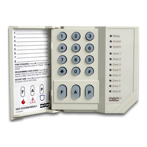
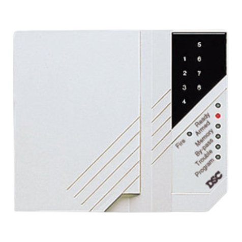
DSC PC1000 User manual

PRINTED
IN
CANADA
COPYRIGHT
1992
DIGITAL
SECURITY
CONTROLS
LTD.
1645
FLINT
ROAD,
DOWNSVIEW,
ONTARIO,
CANADA
M3J
2J6
29000009
R3
OCT
221993
INSTRUCTION
MANUAL
PClCXX)

Canadian
Department
of
Communications
Notice
NOTICE:
The
Canadian Department of Communications label identifies certified
equipment.
This
certification
means
that
the
equipment
meets
certain
telecommunications network protective, operational and safety requirements. The
Department does not guaranteethe equipmentwill operateto the user's satisfaction.
Before installing this equipment, users should ensure that it is permissible to be
connected to the facilities ofthe local telecommunicationscompany.
The
equipment
mustalsobeinstalled using an acceptablemethodofconnection.
In
some cases, the
company's inside wiring associated with a single line individual service may be
extended bymeansofcertified connector assembly (telephoneextensioncord).
The
customer should be aware that compliance with the above conditions may not
prevent degradation of service
in
some situations.
Repairs to certified equipment should be made by an authorized Canadian
maintenance facility designated by the supplier. Any repairs or alterations made by
the
user
to
this
equipment,
or
equipment
malfunctions,
may
give
the
telecommunicationscompanycauseto requestthe usertodisconnectthe equipment.
User should ensure for their own protection that the electrical ground connections of
the power utility, telephone lines and internal metallic water pipe system, if present,
are connected together. This precaution may be particularly important
in
rural areas.
CAUTION: Users should not attempt to make such connections themselves, but
should contact the appropriate electric inspection authority, or electrician, as
appropriate.
The LoadNumber(LN)assigned to each terminal device denotes the percentage of
the total load to be connected to a telephone loop which is used by the device, to
prevent overloading. The termination on a loop may consist of any combination of
devices subject only to the requirement that the total of the Load Numbers of all the
devices does not exceed 100.
The
Load Number of this unit is
2.
,.,
SYSTEM REFERENCE
ZONE
2
3
4
PROTECTED AREA
AUX
________
_
ZONE
TYPE
KEYPAD ZONE [1), [3)
_______________
_
KEYPAD ZONE [4), [6)
_______________
_
KEYPAD
ZONE[*),[#)
_______________
_
MASTER
CODE NUMBER [1]:
______________
_
PROGRAMMED ACCESS CODE NUMBERS:
[2)
------
[3)
_______
[4]
------
SYSTEM
ENTRY
TIME
___
SECONDS
SYSTEM
EXIT
TIME
SECONDS
MONITORING
STATION
INFORMATION:
ACCOUNT#:
___________
Phone:
_______
_
FOR SERVICE:
CALL:
_______________
Phone:
_______
_
NOTES:
1

INTRODUCTION
Congratulations on your purchaseofthe DSC PC1000BurglarAlarm Control System.
This equipment has been designed to give you the greatest possible flexibility and
convenience in the use of your security system. This booklet is intended to serve as
a handy reference and should be kept
in
a secure place.
Your DSC PC1000 Security System is made up of a control panel, one or more
keypads, and various detectorsand sensors. The control panel will be mounted out
of the way
in
a utility room or basement. The metal cabinet contains the system
electronics, fuses and stand-by battery. There is normally no reason for anyone but
the installer to have access to the control panel. The keypad(s) have display lights
and command entry keys. The keypad is used to send commandsto the system and
todisplaythe currentsystemstatus. Keypadsare mounted in convenientareas close
to the exit-entry doors. The security system has up to four zones or areas of
protection. Each zone used will have connected to it various sensors, such as door
or window contacts, motion detectors, glassbreak detectors and vibration or shock
sensors. When a sensor is
in
alarm, a keypad light will be on to indicate which zone
is
in
alarm. The "Ready" light on the keypad will come ON when all the detectors are
closed. The "Ready" light indicates the system is ready to arm.
IMPORTANT
NOTICE
Digital Security Controls Ltd. recommends that you read this manual carefully and
become familiar with the operation of your security system. Check with the installer
to seewhich commands listed in this manual applyto your particularsecurity system.
Fill
out the system reference sheet and store this booklet in a secure place for future
reference.
It
is
important to test your system every week.
To
do
this, first inform the
monitoring station that you are testing your system. Then, with the system disarmed,
activateall detection sensors one at a time and observe the zone lightcome on at the
keypad as each sensor is activated. Perform a bell test by using the
[*],[4]
command. The
PC
1000canbeprogrammed atthe timeofinstallation to automatically
perform a test transmission to the monitoring station on a regular basis.
If
the system
has not been programmed for this automatic test, call the monitoring station for
instructions
on
how to perform a test transmission. Don't forget to inform the
monitoring station when you have finished your test.
Check to see if the "System" light is on when arming the system. The "System" light
will be on
if
a zone is bypassed, an alarm has occurred, or if there is a system trouble
condition. See the Trouble Display section
in
this manual for a description of the
different trouble conditions. Contact your installer for assistance if the trouble
condition cannot be located and corrected.
IMPORTANT
NOTE------------
Rememberthat nosecuritysystemcan preventemergencies.
It
isonly
intended to alert you
in
case of an emergency and should not take the
place of prudent security practices or life and property insurance.
2
MASTER CODE
The4digitMasterCodeisusedfor arminganddisarmingthesystem, for programr:ning
additional access codes, and for changing other features. The Master Code will be
supplied to you by your installer. All keypad entries are made by pressing one key
at a time, with the exception of keypad zone activation.
ARMING
They "System" lightis awarning light. Determine why the "System" light is ON before
arming the system. See the System Display Light section
in
this manual.
To arm the system, first close all protected doors and windows and stop movement
in
areas covered by motion detectors. Check to see that the "Ready" light is
ON
(all
zonesare closed). The system cannotbearmed unlessthe "Ready" lightis ON. Enter
a[4digitaccesscode]. As each digitis entered, thekeypadsounderwill beep. Once
the correct access code
is
entered, the "Armed" light will come ON and the keypad
sounderwill beep quickly.
If
the accesscodewas entered incorrectlyor the "Ready"
light was not ON, the keypad sounder will beep
ste_adily
for 2 second~. ':"'hen the
correct code is entered and the system is armed, exit through the door
1nd1cated
by
your installer as the exit-entry door. At the end of the allowed exit time, all lights
on
the keypad will
go
OFF
except for the "Armed" light.
DISARMING
Enterthe premises only through the door indicated byyour installer as the entry door.
The
keypad sounderwill beON. Goto the keypad and enterthe [4digitaccess~ode].
If
an
error
is
madeentering the code, press
the[#]
key and enter the code again. Do
not repeatedly enter the access code without first pressing the [#] key. Once the
correctaccesscodeisentered, the "Armed" lightwill
go
OFFand the keypadsounder
will stop. The correct access code must be entered before the allowed entry time
expires.
If
an alarm occurred while the panel was armed, the "System" light and the light for
the zone which caused the alarm will start to flash and will continue flashing for 2
minutes.
To
stop the flashing display, press the [3] key and the system will return to
the Ready state.
If
you return home and find an alarm hasoccurred while you were away, it is possible
that an intruder may still be on the premises. Go to a neighbour's and if your system
is monitored, call the monitoring station. Theywill advise what action has been taken
as a result of the alarm and whether the premises are safe to enter.
If
your system
is not monitored, call the local police to investigate.
SYSTEM DISPLAY
LIGHT
The "System" light is a warning indicator for any of the following conditions.
It
indicates there
is
a bypassed zone; there is system trouble; or that an alarm has
occurred since the last time the system was armed. When the "System" light is ON,
press[*]
[1] tocheck for a bypassed zone.
Press[*]
[2] to checkfor system trouble.
Press [
*]
[3) to see if there was an alarm during the last armed period. See Zone
Bypassing, Trouble Display and the Alarm Memory sections
in
this booklet.
3

ZONE BYPASSING
Bypassedzones
do
not
cause
an alarm. Usezone bypassingwhen
access
is needed
to part of the
protected
area. Also,
damaged
wiring or contacts on a zone may be
temporarily
bypassed
until repairs
can
be
made
so that the panel can be armed.
To
bypass
zones, enter
(*],[1]
and
the zone number(s) to be
bypassed
(i.e. [1] for
zone
1,
[2] for zone 2). To remove all bypasses, enter
[*],[1],[0].
The zone lights
which are ON indicate
bypassed
zones. Press [#] to return to Ready.
When the system is installed, the ability to
bypass
certain zones may be eliminated
for security reasons.
In
this case, the zone lights for those zones will not come on
in
response to the
bypass
command.
The "System" light is ON as long as at least ONE zone is bypassed. Do not
unintentionally
bypass
zones when arming. Programmed zone bypasses are
automatically
cancelled
each time the panel is disarmed and must be re-applied
before the next arming.
TROUBLE DISPLAY
The control panel continuously monitors a
number
of possible trouble conditions. If
one of these conditions occurs, the keypad sounder will
beep
and
the keypad
"System" indicator will
come
ON. Press
the[*]
then [2] keys to display the type of
trouble. The zone lights indicate the
type
of trouble condition.
ZONE
LIGHT
TROUBLE
1 Low Stand-by Battery
2 AC Power Failure (see note below)
3 Zone 4 Emergency Circuit Trouble
4 Unsuccessful Communication Attemptwith Monitoring Station
Press the [#] key to return to Ready.
NOTE:
The
keypad
buzzerwill notsound for AC failure until there is alsoa lowbattery
condition. The "System" lightwill
come
ONas soon asAC fails
and
will remain on until
AC restores.
ALARM
MEMORY
DISPLAY
If an alarm
occurred
during the last
armed
period, the "System" light will be ON.
Press
the[*]
then [3] keys to
display
the zone(s) which
caused
the alarm.
Press[#]
to return to Ready.
ALARM
TEST
Press [
*l
then [4] for a 2
second
test of the keypad lights, keypad sounder and the
bell/siren alarm.
4
l
'
r
PROGRAMMING ADDITIONAL ACCESS CODES
Programming additional
access
codes
can only
be
done
with the Master Code.
To
program a new
access
code, enter [
*l,
[5]
and
[Master Code]. Zone light 1will
be ON to indicate that the Master Code is already programmed. If other
codes
are
programmed, the respective zone lights will
be
on (i.e. zone light 2 will be ON to
indicate that a second
code
has been programmed).
Press any key from (2] to (4] to select which
of
the 3 additional
codes
is to be
programmed. The zone lightwill flash to indicate which
code
is
being
programmed.
Now
entera (4
digit
access
code].
Do
not use
the[*]
or[#]
keys as part of the code.
The systemwill
acknowledge
the new
code
by
beeping
several times. The zone light
will stopflashing
and
remain ON toindicatea
programmed
code. Afterthe new
code
has been entered, enter a
number
from [2] to (4] to
program
another code, or press
[#] to return to Ready.
If (
****l
instead of a (4
digit
code]
is entered,
any
previously
programmed
code
in this location will beeliminated. The zone lightwill
go
OFF after [* * *
*]
is entered
to indicate that there is no longer a
code
programmed
in this location.
Note that during
code
programming, the zone light is
ON
steadily for
codes
which
have already been programmed. Note that the Master
Code
is always indicated
by
the zone 1 light. To program a new Master Code, enter [
*],
(5], [CURRENT Master
Code], (1], [NEW Master Code]. Do not
enter[*]
or[#]
as part of the new Master
Code, and
do
not try to erase the Master
Code
by
entering[****].
Summary:
To
program a new code:
Enter(*],
[5], [Master Code], (2 to 4], (4
digit
code]
When
code
is programmed,
press[#]
to return to Ready.
To
eliminate
an
existing code:
Enter [
*],
[5], [Master Code], (2 to 4],
[****]
When
code
is erased,
press[#]
to return to Ready.
QUICK-ARM FEATURE
When the Quick-Arm feature is enabled, the panel
may
be armed simply
by
entering
[*],[OJ
insteadofa 4
digit
code. The [* ],
[OJ
command
will notdisarmthe panel. This
feature is useful when individualsare required to
arm
the system, but are notdesired
to beable to disarmitas well. In the home, this feature
could
be
used
forvisitors,
and
in acommercialapplication, it could
be
used
with junioremployees
and
maintenance
staff.
To
activate the Quick-Arm feature, enter [
*l,
[5], [Master Code], [5] (note that keys
1to 4 are used to
program
codes). When the
command
is entered, the
keypad
will
beep
3 times if the feature is being
enabled
and
will
beep
once
if the feature is being
disabled.
Press
[#]
to return to Ready.
5

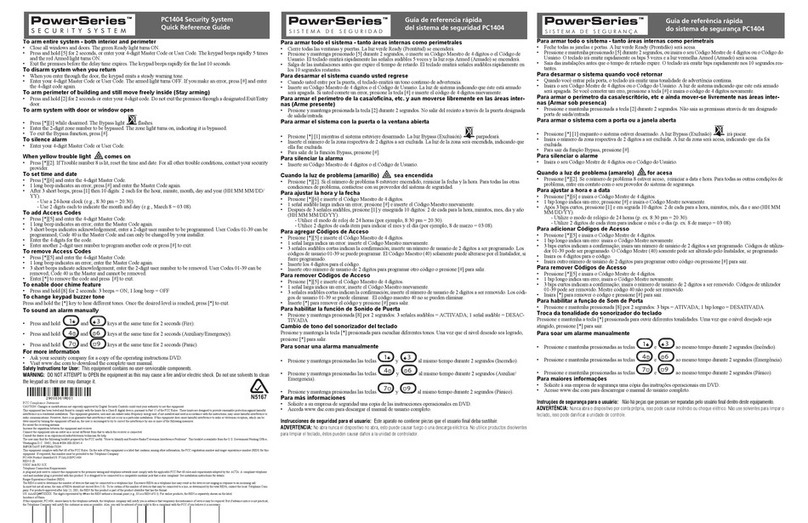
"Ready" light ON: system ready for arming.
"Ready" light
OFF:
openzone; zone must be
---~
closed or bypassed before arming. •····· ,
,.-,....:··'<"
"-
►
>?>+vd:>··
"Armed"lightwill comeON indicatingsystem
is armed. To arm: ensure "Ready" light is on,
&---+-----+
then enter [4 digit access code].
"System" light
ON
indicates a bypassed
___
_,
zone, a system trouble or an alarm memory. f
t
To bypass a zone: press [
*l
then [1] and
then the zones you wish to bypass. Zone
lights will be ON for bypassed zones.
To display system trouble conditions:
press [
*l
then [2]. The source of the
trouble will be indicated by a zone light
coming ON:
Zone 1: low battery
Zone
2:
AC
power failure
Zone
3:
emergency circuit trouble
Zone
4:
communication failure
To display the zone that caused an
alarm: press [
*l
then [3]. Zone light will
come ON to indicate which zone caused
an
alarm. Press [#] to return to Ready.
II
Rnax;fy
Arfti~.(j.
•
System
•
Zon~.1
a Zone i
•
Zone3
•
Zone
4
"Zone" light(s) when ON
in
the normal
operating mode indicate an open zone (e.g.
an open door, window, etc.)
l
,/
PClOOO
.---------.---------1
Press [1] and [3] at the same
time
in
a fire situation.
ADDITIONAL ACCESS CODES are
programmed
by
pressing [
*l
then [5]
then entering the [Master Code].
"System" light will flash; select which
code you want to program by
pressing a single key [2) to [4). Then
enter the [4 digit access code].
Press[#) to return to Ready.
Press [4] and [6] at the same
time to send an auxiliary
alarm transmission.
.__
____
__,_
______
--1
Press[*]
and[#]
at the same
time to summon police.

DOOR
CHIME
FEATURE
The
door chime feature is used, while the panel is disarmed, to provide a tone from
the keypad eachtime adoororwindowisopenedorclosed. The doorsand windows
which will provide this indication are programmed by your installer.
Enter[*]
[5], [Master Code],
[OJ
to
turn the door chime feature
ON
and
OFF.
When
the command is entered, the keypad will beep3 times if the feature
is
being enabled
and will sound one beep if the feature is being disabled.
SPECIAL
FUNCTION
COMMAND
The PC1000 can be programmed at the time of installation
to
operate other devices
suchas electric doorstrikes, dooropeners, electric lights, cameras, etc. bypressing
[*]
then [7]
on
the keypad. Your installerwill instructyou on the useof this command.
AT-HOME ARMING
COMMAND
Entering[*],
[9] before the 4 digit arming code arms the panel with no entry delay
on
the entry zones, and bypasses the interior zones that have been programmed as
"home-away" zones. This command is used to arm the system if someone is
remaining
on
the premises.
KEYPAD ZONES
There are three zones which can be activated from the keypad. A fire alarm is
activated by pressing the [1] and [3] keys at the same time. The fire alarm sounds
the bell/siren
in
a pulsed mode. A transmission will be sent to the monitoring station
ONLY if it has been programmed to
do
so by the installer.
The PC1000 can be programmed at the time of installation to send a transmission to
the monitoring station
by
simultaneously pressing keys [4] and [6]. The installer will
provide instructions
on
its use when required.
The Police (or Panic) alarm is activated by pressing the
[*land[#]
keys at the same
time. The panic alarm can be programmed to be audible or silent. There is
no
annunciation from the keypad. A transmission will be sent to the monitoring station
ONLY if it has been programmed to
do
so by the installer.
AUTO-TEST
TRANSMISSION
The
PC
1000can be programmed at the time of installation to send a test code
to
the
monitoringstationatregularintervals. The frequencyandtimeofthetesttransmission
is set by the monitoring station and should not be changed without their knowledge.
8
FIRE LOOP OPERATION
ARMED MODE ("Armed" light ON)
1.
On
alarm the signal will pulse.
2.
Enter access code to silence the signal and also disarm the panel.
3.
Press
[*l
then [7]
to
reset the smoke detector(s) if the panel has been
programmed
to
do
so;
"System" and "Ready" lights will come
ON
steadily.
DISARMED MODE ("Ready" light ON)
1.
On
alarm the signal will pulse; zone 4 and "System" lights
ON
steadily
2.
Enter access code to silence signal.
3.
Press
[*]
then [7] to reset the smoke detector(s) if the panel has been
programmed to do
so;
"System" and "Ready" lights will come ON steadily.
FIRE LOOP TROUBLE
1.
Open circuit
on
the fire loop (zone 4
);
"System" light
ON
steadily and keypad
sounder beeps.
2.
Press [#] to silence the trouble.
3.
Press
[*]then
[2] to view the source of trouble; "System" and zone 3 lights flash
to indicate a trouble
on
the fire loop (zone 4).
4.
Press[#]
to
exit view-trouble mode; "Ready" and "System" lights will come
ON
steadily.
5.
When the trouble condition is repaired, the "System" lights will
go
OFF
leaving
only the "Ready" light
ON.
TESTING
IT
IS
RECOMMENDED
THAT
THE
SYSTEM
BE
TESTED
ON
A
WEEKLY
BASIS
NOTE: Perform system tests
in
the
off-peak hours, such as early morning or late
evening.
1.
Inform the monitoring station that you are testing your system.
2.
Disarm the system ("Ready" light should be ON).
3.
Perform a battery/bell test by
pressing[*]
then [4]. The alarm will sound for
about 2 seconds.
If
a trouble occurs after the test,
press[*],
[2] to view the
trouble condition.
4.
Activate each sensor
in
turn (e.g. open a door or window). Observe the zone
light come
ON
as each sensor
is
activated. The zone light will
go
OFF
as each
sensor is restored
to
normal (door or window is closed).
5.
Press the [1] and [3] keys at the same time. The signal will sound
in
a pulsed
mode. Arm then disarm the panel to silence the signal.
Continued...
►
9

TESTING
(Continued)
6.
If
zone 4is setasaFire zone, activationwill cause the signal to sound
in
apulsed
mode. CAUTION: Do not use open flame
or
burning materials
to
test a
smoke detector. Contact your installer for information on safe methods to
activate a smoke detector.
7.
Should your system fail to operate properly, call your installer for service.
8.
When testing is complete, call and advise the monitoring station.
MAINTENANCE
With normal use, the system requires minimum maintenance. The following should
be observed:
1.
Donot wash the keypad with a wet cloth. Light dusting with a barely dampcloth
should remove normal accumulations of dust.
2.
The battery/bell test is designed to determine battery condition, however it is
recommended that the stand-by battery be replaced every three years.
3.
For other system devicessuch as smoke detectors, passive infrared, ultrasonic
or microwavemotion detectors or glassbreak detectors, consult the respective
manufacturer's literature for testing and maintenance.
FIRE
SAFETY
IN
THE
HOME
Most fires occur
in
the home and to minimize this danger it
is
recommended that a
household fire safety audit be conducted and a family escape plan be developed.
HOUSEHOLD
FIRE
SAFETY
AUDIT
1.
Are all electrical appliances and outlets in a safe condition? Check for frayed
cords, over-loaded lightingcircuits, etc.
If
you are uncertain aboutthe condition
ofyourelectricalappliancesorhouseholdservice, haveaprofessionalevaluation.
2.
Are all flammable liquids stored safely
in
closed containers in a well ventilated
cool area? Cleaning with flammable liquids should be avoided.
3.
Are fire hazardous materials (matches) well out of reach of children?
4.
Are furnaces and wood burning appliances properly installed, clean and
in
good
working order? Have a professional evaluation.
FAMILY
ESCAPE
PLANNING
There is often very little time between the detection of a fire and the time
it
becomes
deadly.
It
is thus very important that a family escape plan be developed and
rehearsed.
1.
Every family member should participate in developing the escape plan.
2.
Studythe possibleescaperoutes from each location within the house and since
manyfires occurat night, special attention should begiven to the escape routes
from sleeping quarters.
Continued...
►
10
FAMILY
ESCAPE
PLANNING
(Continued)
3.
It
is
essential that escape from a bedroom be possible without opening the
interior door. Consider the following when making your escape plans:
• Make sure that doors and windows that open to the outsideare easily opened.
Ensure that they are are not painted shut, and that their locking mechanisms
operate smoothly.
•
If
opening the exit or using the exit is too difficult for children, the elderly or
handicapped, plans for rescue should be developed. This includes making
sure that those who are to perform the rescue can promptly hear the fire
warning signal.
•
If
the exit
is
above the ground level, an approved fire ladderor rope should be
provided as well as training
in
its use.
• Exits on the ground level should be kept clear.
Be
sure to remove snow from
exterior patio doors
in
winter; outdoor furniture or equipment should not block
exits.
• The family should have a predetermined assembly point where everyone can
be accounted for; for example, across the street or at a neighbour's house.
• Once everyone
is
out of the house, call the Fire Department.
• A good plan emphasizes quick escape. Do not investigate first or attempt to
fight the fire, and do notattempt to rescue belongings or pets as this takes up
valuable time. Once outside,
do
not re-enter the house. Wait for the fire
department.
• Write the plan down and rehearse frequently, so that should an emergency
arise, everyone will know what they are to do. Revise the plan as conditions
change; for example, when there are more or fewer family members
in
the
home, or if there are changes to the house.
• Make sure your fire warning system is operational by conducting weekly tests
as noted elsewhere
in
this manual.
If
you are unsure about system operation,
contact your installing dealer.
•
It
is
recommended that you contact your local fire department and request
further information on home fire safety andescape planning.
If
available, have
your local fire prevention officer conduct an in-house fire safety inspection.
11

LIMITED
WARRANTY
Digital Security Controls
ltd.
warrants that for a period of twelve months from the date
of purchase, the productshall befree from defectsin materialsandworkmanship under
normal useandthatin fulfilment ofanybreechofsuchwarranty, Digital SecurityControls
Ltd. shall, at its option, repair or replace the defective equipment upon return of the
equipment to its repair depot. This warranty applies only to defects in parts and
workmanship
and
not to damage incurred in shipping or handling, or damage due to
causesbeyondthe control ofDigital SecurityControlsLtd., suchas lightning, excessive
voltage, mechanical shock, water damage, or damage arising out of abuse, alteration
or improper application of the equipment.
The foregoing warranty shall apply only to the original buyer, and is and shall be
in
lieu
ofany andall otherwarranties, whetherexpressed orimpliedand ofall other obligations
or liabilities on the part of Digital Security Controls Ltd. Digital Security Controls Ltd.
neitherassumes, norauthorizesanyotherperson purportingto
act
onitsbehalftomodify
or to changethis warranty, norto assume for itanyotherwarranty orliability concerning
this product.
In
no event shall Digital Security Controls Ltd. be liable for any direct or indirect or
consequential damages, loss of anticipated profits, loss of time or any other losses
incurred
by
the buyerin connectionwith the purchase, installation oroperationorfailure
of this product.
WARNING:
Digital Security Controls Ltd. recommends that the entire system be
completely tested on a regular basis. However, despite frequent
testing,
and
due
to
but
not limited to, criminal tampering or electrical
disruption, it is possible for this
product
to fail to perform as expected.
FCC COMPLIANCE
CAUTION:
Changes or modifications notexpressly approved
by
Digital Security Controls Ltd.
could void your authority to use this equipment.
This equipmenthas been tested and found tocomplywith the limitsfor a Class B digital device,
pursuantto Part 15ofthe FCC Rules. Theselimitsaredesignedtoprovidereasonableprotection
against harmful interference in a residential installation. This equipment generates, uses and
can radiate radio frequency energy and, if not installed and used
in
accordance with the
instructions, may cause harmful interference to radio communications. However, there is no
guaranteethatinterferencewill not
occur
inaparticularinstallation. Ifthisequipmentdoescause
harmful interference to radio
or
television reception, which can
be
determined by turning the
equipment off
and
on, the user is encouraged to try to correct the interference
by
one or more
of the following measures:
• Re-orient the receiving antenna.
• lncreas.e the separation between the equipment and receiver.
• Connect the equipment into an outlet on a circuit different from that to which the receiver
is connected.
• Consult the dealer or an experienced radio/television technician for help.
The user may find the following booklet prepared
by
the FCC useful: "How to Identify and
Resolve Radio/Television Interference Problems". This booklet is available from the U.S.
Government Printing Office, Washington D.C. 20402,
Stock#
004-000-00345-4
12
Important
Information
This equipment complies with Part 68 of the FCC Rules. On the side of this equipment is a label
that contains, among other information, the FCC registration number of this equipment.
Notification
to
Telephone
Company
Upon request, the customer shall notify the telephone companyof the particular line to which the
connection will bemade, and provide the FCC registration number and the ringer equivalence of
the protective circuit.
FCC Registration Number: F534J3-19591-AL-R
Ringer Equivalence Number:
0.18
USOC Jack: RJ-31X
Telephone
Connection
Requirements
Exceptfor the telephonecompanyprovidedringers, all connectionstothetelephonenetworkshall
bemade through standard plugs and telephone company provided jacks, or equivalent, in such
amannerasto allow for easy, immediatedisconnection oftheterminal equipment. Standardjacks
shall be so arranged that. if the plug connected thereto is withdrawn, no interference to the
operation of the equipmentat the customer's premiseswhich remainsconnectedtothetelephone
network shall occur
by
reason of such withdrawal. Ensure that plugs and jacks meet the
dimension, tolerance and metallic plating requirements of 47 C.F.R. Part 68 Subpart
F.
Incidence
of
Harm
Should terminal equipment or protective circuitry cause harm to the telephone network, the
telephone company shall, where practicable, notify the customer that temporary disconnection
ofservicemayberequired; however,wherepriornoticeisnotpracticable,thetelephonecompany
may temporarily discontinue service if such action is deemed reasonable in the circumstances.
In
the case of such temporary discontinuance, the telephone company shall promptly notify the
customer and will be given the opportunity to correct the situation.
Additional
Telephone
Company
Information
The
security control panel must beproperlyconnected to the telephone line with a USOC
RJ-31
X
telephone jack. The
FCC
prohibitscustomer-provided terminal equipment beconnectedtoparty
lines or to be used in conjunction with coin telephone service. Inter-connect rules may vary from
state to state.
Changes
in
Telephone
Company
Equipment
of
Facilities
The
telephone company may make changes
in
its communications facilities, equipment,
operationsor procedures,where such actionsare reasonablyrequiredandproperin itsbusiness.
Should any such changes render the customer's terminal equipment incompatible with the
telephonecompanyfacilitiesthecustomershallbegivenadequatenoticetotheeffectmodifications
to maintain uninterrupted service.
Ringer
Equivalence
Number
(REN)
The
REN
is useful to determine the quantity of devices that you may connect to your telephone
line and still have
all
ofthose devices ring when your telephone number is called. In most, butnot
all areas, the sum of the RENs of all devices connected to one line should not exceed five (5.0).
To becertain ofthe numberof devices that you may connectto your line, you maywanttocontact
your local telephone company.
Equipment
Maintenance
Facility
If you experience trouble with this telephone equipment, please contact the facility indicated
below
for
information on obtaining service or repairs. Do not return equipment to this address
without prior authorization. The telephone company mayask that you disconnectthis equipment
from the network until the problem has been corrected or until you are sure that the equipment is
not malfunctioning.
Digital Security Controls Ltd.
160 Washburn Street
Lockport,
NY
14094
Please note that this facility willonly
accept
preauthorizedshipments from DSCdistributors.
Ifyou have problems with your system, contact your installer
or
service representative for
assistance. Products received withoutan authorization number will notbe accepted.
Other manuals for PC1000
3
Table of contents
Other DSC Security System manuals

DSC
DSC Power608 User manual

DSC
DSC MAXSYS PC4020 User manual

DSC
DSC PC-LINK9 User manual

DSC
DSC ALEXOR Owner's manual

DSC
DSC WS4965 User manual

DSC
DSC Maxsys PC6010 User manual

DSC
DSC Impassa WT8911 User manual

DSC
DSC Classic PC580 User manual

DSC
DSC Power832 PC5O15 User manual

DSC
DSC PowerSeries Neo 3G8080 User manual

DSC
DSC Voice Assisted Security Control Escort5580TC User manual

DSC
DSC Impassa WT4911 User manual

DSC
DSC neo HS2016 User manual

DSC
DSC Power832 PC5010 User manual

DSC
DSC Power832 P5010 User manual

DSC
DSC PC2525 User manual

DSC
DSC PC500 User manual

DSC
DSC MAXSYS PC4020 User manual

DSC
DSC New Classic PC585 User manual

DSC
DSC Power 832 PC5010 User manual