METBERG T3000 User manual


1
CONTENTS
Page No.
Section 1.0 General Information. 4
1.1 Copyright 4
1.2 Foreword / Reservation of rights 4
1.3 Terms and Descriptions Used in this Manual 4
1.4 Warranty 4
1.5 Specification Alterations 5
1.6 Machine Specification 5
1.7 Familiarisation 6
1.8 Optional Equipment 6
1.9 Correct Use of the Machine 7
Section 2.0 Safety. 8
2.1 Safety Introduction 8
2.2 General Safety Rules 8
2.3 Hazard Warning Signs 9
2.4 Hazard Warning Signs on the Machine 11
2.5 Hazard Warning Signs in this Manual 12
2.6 Hazard Zone 12
2.7 Personal Protective Equipment 12
2.8 Plant Hazards – Working at Heights 12
2.9 Plant Hazards – Electrics 13
2.10 Plant Hazards – Hydraulics 13
2.11 Plant Hazards – Manoeuvring on site 13
2.12Plant Hazards – Nip Points 13
2.13 Plant Hazards – Material Falling from Heights 14
2.14 Safety Guards on the Machine 15
2.15 Emergency Stops on the Machine 15
2.16 “Lock Out” Procedure 16
2.16.1 Before Carrying Out Any Work on the Machine 16
2.16.2 After Carrying Out Any Work on the Machine 16
2.17 Emergency Shut Down Procedure 17
2.18 Restart Procedure after Emergency Shutdown 17
2.19 Testing the Emergency Stops 17
2.20 Safety Before and During Setup 17
2.21 Safety Before and After Setup 18
2.22 Safety Before and During Maintenance 18
2.20 Safety Before and During Transport 19
Section 3.0 Initial Setup. 20
3.1 Safety Before and During Setup 20
3.2 Initial Inspection 20
3.3 Machine Location Considerations 21
3.4 Measures Before Setup 21
3.5 Initial Setup 21
3.5.1 Starting the Machine 21
3.5.2 Fold Out Oversize Conveyor 22

2
Section 4.0 Standard Operation Procedures. 23
4.1 Safety Before and During Operation 23
4.2 Pre-Operation Checks 23
4.3 Initial Setup 24
4.4 Starting the Machine 24
4.5 Manual Tracking with Umbilical Handset 25
4.6 Normal Operation 26
4.7 Shutting Down the Machine 26
Section 5.0 Maintenance. 27
5.1 Safety Before and During Maintenance 27
5.2 Regular Maintenance 28
5.3 Check Fuel Level and Top up 28
5.4 Adjusting Trommel Brush 29
5.5 Tracks 29
5.5.1 Track Tension 30
5.5.2 Track Gearbox Oil Level 31
5.5.3 Cleaning the Tracks 31
5.6 Control System 31
5.7 Daily Maintenance 31
5.8 Weekly Maintenance 32
5.9 2 Weekly / 100 Hour Maintenance 32
5.10 Monthly / 500 Hour Maintenance 32
5.11 1000 Hour Maintenance 33
5.12 2000 Hour Maintenance 33
5.13 CAT 2.2 Engine Maintenance 33
5.13.1 When Required 33
5.13.2 Daily 33
5.13.3 Weekly 34
5.13.4 Every 250 Service Hours 34
5.13.5 Every 500 Service Hours 34
5.13.6 Every 1000 Service Hours 34
5.13.7 Every 1500 Service Hours 34
5.13.8 Every 2000 Service Hours 34
5.13.9 Every 3000 Service Hours 34
5.13.10 Every 4000 Service Hours 35
5.13.11 Every 6000 Service Hours 35
5.14 Lubrication Schedule 36
5.14.1 Tail and Drive Drum Bearings 36
5.15 Hydraulic System 37
5.15.1 Adding Hydraulic Oil 37
5.15.2 Changing Hydraulic Oil 37
5.16 Belt Adjustment – Safety Precautions 38
5.16.1 Belt Tracking 38
5.16.2 Belt Tensioning 38
5.16.3 Belt Alignment 39
Section 6.0 Transportation. 40
6.1 Safety Before and During Transportation 40
6.2 Removing Machine from a Low Loading Trailer 40

3
6.3 Putting the Machine into Transport Position 42
6.3.1 Folding the Oversize Conveyor to Transport Position 42
Section 7.0 Fault Finding. 43
Section 8.0 Spare Parts. 44
8.1 Spare Parts Ordering Information 44

The manufacturer, Metberg Ltd., declares under our sole responsibility that the
assembled equipment:
TROMMEL T3000 SCREENING PLANT S/N 007-01-2020
Complies with the provision of Council Directive: Machinery 98/37/EC as amended, and
with the regulations transposing it into national law.
Complies with the provisions of the following harmonised standards: EN 294:1992; EN
349:1993; EN 1050:1996; EN ISO 12100-1:2003; EN ISO 12100-22003.
The hereby declaration is valid provided that the described instructions and guidelines in
the manuals are respected, particularly those related to safe operation.
Created at : MetbergLtd.
136CorkillRoad
Eskra
Co.Tyrone
N.Ireland
Dated: 6 t h J a n u a r y 2 0 2 0
Name of Signatory:
Liam O
Liam OLiam O
Liam O’
’’’Hanlon
HanlonHanlon
Hanlon
ManagingDirector
EU DECLARATION OF CONFORMITY

5
SECTION 1.0 GENERAL INFORMATION
1.1 COPYRIGHT
No copies or reproductions may be made from this manual without prior consent of Metberg
Ltd. This manual, complete or in part, must not be loaned to a third party.
Additional copies of this manual are readily available; however, a charge may be made to
cover printing and administrative costs.
1.2 FOREWORD / RESERVATION OF RIGHTS
This manual has been produced to assist you to promote safe, correct and efficient
operation and maintenance of the plant, during its operating life time. By following these
instructions, you will help to reduce the risk of accidents, keep repair costs to a minimum and
increase plant reliability.
We strongly recommend that the customer, their Health and Safety Staff, plant operators
and maintenance staff should read and understand all aspects of this manual. Particular
attention should be paid to the safety and maintenance sections.
Keep a copy of this manual at the operational site at all times.
All information, illustrations and specifications in this manual are based on the latest
information available at the time of publication.
While all attempts have been made to ensure that the information contained in this manual
are correct, some variations exist between different plant designs, due to customer
specifications. Therefore, some of the information contained within this manual may not be
specific to every customer’s plant.
1.3 TERMS AND DESCRIPTIONS USED IN THIS MANUAL:
This manual refers only to the machine supplied by Metberg. Feed and discharge systems
connected by the customer and / or not supplied by Metberg, are not covered by this
manual.
Where Metberg Ltd have supplied but not installed the machine or any of the components
specified in this manual, it will take no responsibility for any incident, accident, injury, loss or
damage howsoever caused during installation or due to improper or incorrect installation or
set-up.
The following terms have been used throughout:
(i) Trommel
This refers to the group of components which go together to make up the machine supplied
by Metberg Ltd.
(ii) Customer
This refers to the individual, group or company who have purchased the machine from
Metberg Ltd.
(iii) Customer Connection Points
This refers to the points where the customer connects the feed and discharge systems. For
example, the point at which the material is fed onto the machine is a customer connection
point.
(iv) Machine Operator
This refers to the person/s who are authorised to operate and /or maintain the machine
whether it be the owner of the plant, their employees or their representatives. Metberg Ltd.
will take no responsibility for accidents, injuries, damage or loss to or by unauthorised
persons operating, maintaining and /or tampering with the machine.
1.4 WARRANTY
All parts and components supplied by Metberg Ltd, related to any products or services, are
supplied in accordance with the terms set out in the standard terms and conditions of sale.
The company shall endeavour to ensure that all products are manufactured to the highest
standards of the industry and carry a 12-month warranty from the date of delivery, or 2000
hours from the plant commissioning date, whichever is sooner.

6
The company shall in no circumstances be liable for damages of any kind whether direct or
consequential (including but not limited to the loss of profit, expenditure incurred, or delay in
the execution of any work being carried out by or for the customer) arising out of, or in
connection with the manufacture, or servicing, or failure to perform the servicing or failure to
return the equipment or any act done in connection therewith, except:-
Nothing in this clause shall limit the company’s liability for death or personal injury arising out
of negligence.
1.5 SPECIFICATION ALTERATIONS
At the time of initial design Metberg engineers will have determined the correct specification
of the plant to provide the required product and throughput. This specification will have been
determined through consultation with a representative of the customer where process
variables such as throughput, material type, working environment etc, will have been
determined. At the time of commissioning, the plant will be set and verified as providing the
required throughput etc. If, however, at any time in the future the customer wishes to
change any settings on the plant or the parameters in which the plant is operating i.e. the
material being processed, they must first consult Metberg Ltd. Written authorisation must be
received from Metberg before any changes take place.
Where any unauthorised alterations to the settings of the plant or the parameters in which
the plant is working, by the customer, their representative or any other person/s takes place,
warranty will automatically be invalidated. Metberg Ltd, will not be held responsible for any
direct or indirect damage, accident, injury or loss etc. arising from such unauthorised
alterations. Nor will it be held responsible for any loss in throughput, quality of output
material or decrease in plant reliability.
1.6 MACHINE SPECIFICATION.
General Dimensions
Transport Length: 10.8m (35’4”)
Operational Length: 12.4m (40’9”)
Width: 2.2m
Height: 3.2m
Weight: 9500kg
Capacities
Hopper: 2.5m3 (3.2yd3)
Fuel tank: 70 litres
Hydraulic tank: 265 litres
Engine
Type: Caterpillar C2.2 T
Power: 45.5kW
RPM: 2800-3000
Fuel: Diesel
Fuel consumption: 4 litres per hour
Feed Conveyor
Gearbox: Berma RT160
Torque ratio: 2000Nm / 1:8
Hydraulic motor: OMP315
Belt width: 1000mm
Belt length (drum centres): 3.4m
Belt: EP400 4-ply 5mm top
Adjustable speed: 0-13 RPM
7
Fines Conveyor
Hydraulic motor: OMT400
Belt width: 900mm
Belt length (drum centres): 14.5m
Belt: EP400 3-ply 5mm top
Oversize Conveyor
Hydraulic motor: OMT400
Belt width: 750mm
Belt length (drum centres): 8.5m
Belt: EP400 3-ply 5mm top
Drum
Diameter: 1.5m
Length: 3.7m
Hydraulic motor OMT500
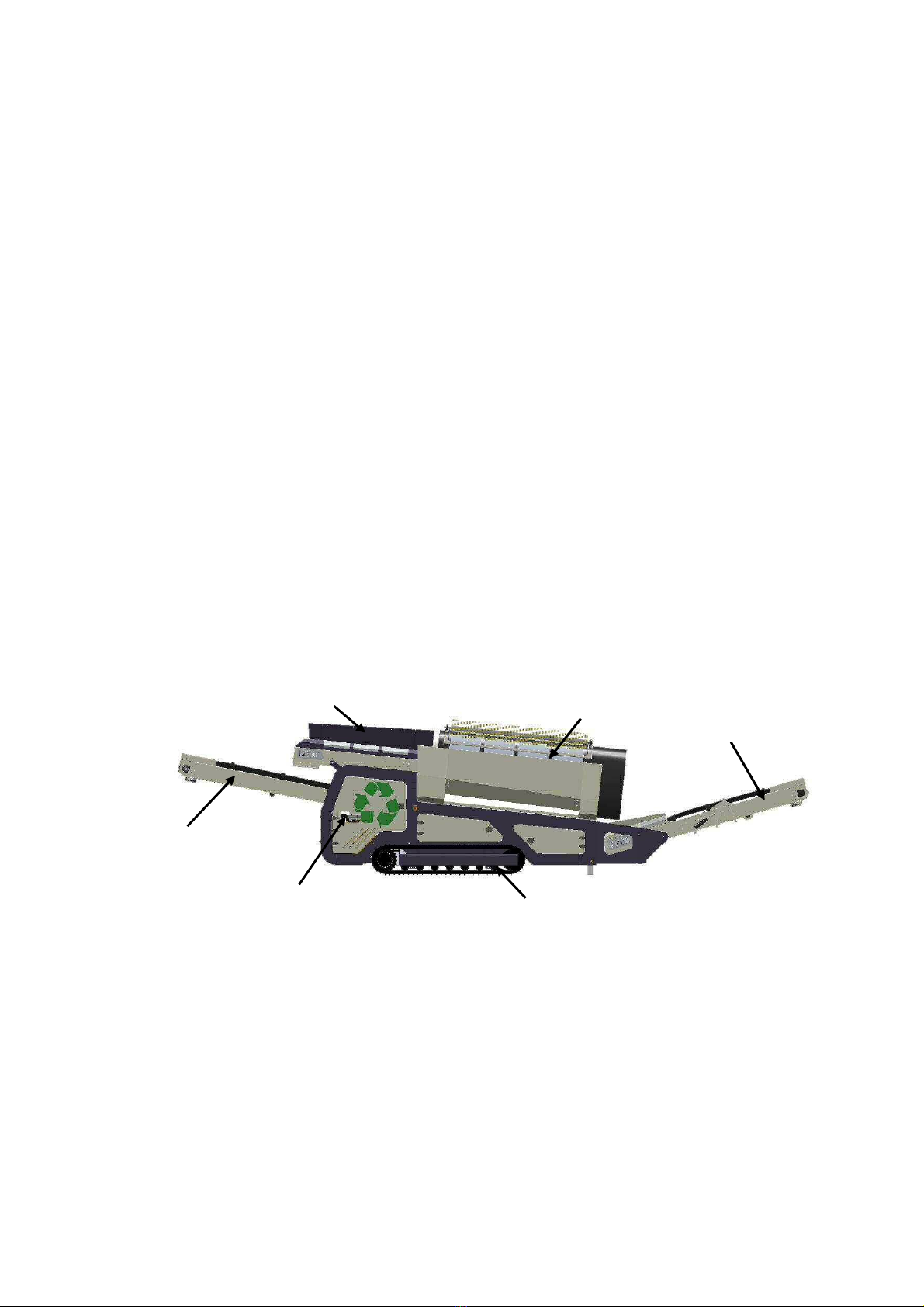
1.7 FAMILIARISATION
The following names and descriptions have been used throughout this operation manual to
describe components and their locations.
1.8 OPTIONAL EQUIPMENT
Machines can include optional equipment and/or special features additional to the standard
specification. These may affect the information given in this manual. Look in the
appendix of this operations manual for any addendum which may relate to additional
equipment or variations to the standard specification. Take note of any variations to the
standard procedures and/or component specifications.
Hopper / Feeder Drum
Fines Conveyor
Oversize Conveyor
Tracks
Control Valves
FRONT
REAR

8
1.9 CORRECT USE OF THE MACHINE
(i). This machine should be used for loading, conveying, screening and stockpiling of
recyclable and aggregate type materials, e.g. Sand, gravel, chalk, ore, topsoil, green waste,
demolition, etc.
This does not include hot materials that could damage the belt etc.
(ii). The machine should be run in a well-ventilated area.
(iii). Appropriate space should be allowed for the loading of the machine and for the
stockpiles of materials that are created.
(iv). The machine should only be loaded via the hopper.
(v). Before operating the machine ensure that it has been properly setup, see section 3.0
(vi). The machine must be levelled across the undercarriage and along the chassis during
installation.
(vii). The machine must be properly maintained as per the maintenance procedures given in
section 5.0.
(viii). The machine must always be properly lubricated as per the lubrication schedule given
in section 5
(ix). Before shutting down the machine, other than in emergency situations, always run all
the material out of the machine. Re-starting the machine with a full load may damage the
drive system.

9
SECTION 2.0 SAFETY
DANGER
Failure to thoroughly read, understand and carry out these safety instructions could
result in death or serious injury
2.1 SAFETY INTRODUCTION
These safety instructions should be read, understood and implemented by the machine
owner, supervisor, operators and/or any other person/s who carries out work on the plant.
All personnel who operate, maintain, repair or carry out any work near or on Metberg
equipment, must be properly trained in the correct and safe procedures for operation, safety,
maintenance and repair etc.
It remains the responsibility of the owner of the machine to ensure the Health and Safety of
all persons who are viewing, operating or carrying out any work on or close to the machine.
This safety section in no way replaces any laws or other binding accident prevention and
environmental protection regulations.
2.2 GENERAL SAFETY RULES
Before operating, maintaining, repairing or carrying out any work on this machine, all
personnel must:
(i). Have read and understood all aspects of this manual and be familiar with all safety
instructions.
(ii). Be aware of all the hazards associated with this machine.
(iii). Know the location of safety features such as remote stop buttons and safety guards etc.
(iv). Know the location of the respective control panel for the machine and operating
features
(v). Have received specific and adequate training for any task to be carried out.
(vi). Be completely familiar with all parts and operation of the machine.
(vii). Be aware of all moving parts on the machine.
(viii). Have read and understood any “on-site” safety manual produced by the site owner.
(ix). Be aware of the performance limits of the plant
(x). Use the machine only as it was intended to use.
(xi). Carry out all safety instructions regardless of how unimportant they may seem.
(xii). Ensure that all “Personal Protective Equipment” is worn.
10
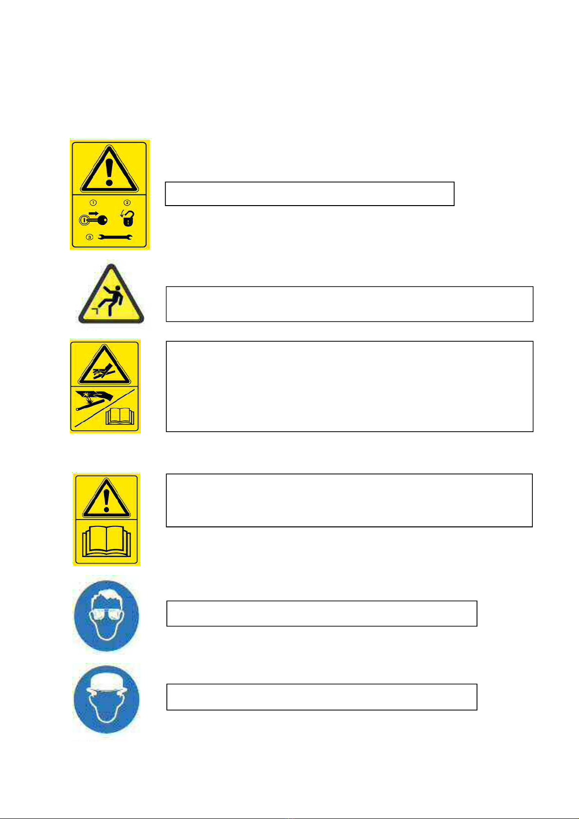
2.3 HAZARD WARNING SIGNS
The following hazard signs may be used on your machine please ensure that you make
yourself familiar with these and the corresponding level of hazard
FALLING HAZARD - DO NOT CLIMB ON TO WORKING MACHINERY.
LOCK OUT EQUIPMENT BEFORE SERVICING.
BEWARE OF HYDRAULIC OIL LEAKS. HIGH PRESSURE HYDRAULIC
OIL CAN PENETRATE THE SKIN CAUSING SERIOUS INJURIES. USE
REPORT ALL LEAKS TO THE APPROPRIATE PERSONNEL
RESPONSIBLE. ONLY TRAINED AND PROFESSIONAL PERSONNEL
ARE PERMITTED TO INSPECT LEAKS.
OPERATOR MANUALS MUST BE READ AND FULLY UNDERSTOOD,
BEFORE PERFORMING ANY OPERATION OR MAINTENANCE TASKS.
EYE PROTECTION MUST BE WORN IN THIS AREA
HEAD PROTECTION MUST BE WORN IN THIS AREA
11
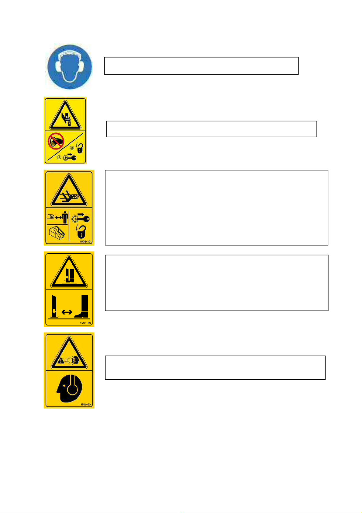
EAR PROTECTION MUST BE WORN IN THIS AREA
NIP POINT - KEEP HANDS CLEAR OF MOVING MACHINERY
NIP & ENTANGLEMENT POINT. ONLY TRAINED PERSONNEL ARE
PERMITTED TO OPERATE MACHINERY WITH THIS HAZARD SIGN.
ALL LOOSE CLOTHING AND HAIR MUST BE TIED UP. ALL
PROTECTIVE GUARDS MUST BE IN PLACE WITH ALL BOLTS
PROVIDED AND ONLY REMOVED ONCE THE MACHINERY HAS
BEEN STOPPED AND LOCKED OUT. MAINTENANCE TASKS MUST
ONLY BE PERFORMED ONCE THIS HAS BEEN DONE AND ONLY BY
TRAINED PERSONNEL.
CRUSHING HAZARD – JACKS. ONLY TRAINED OPERATORS OR
PERSONNEL ARE PERMITTED TO STAND NEAR MACHINERY WITH
THIS HAZARD SYMBOL. DO NOT USE BODY PARTS (EG HANDS,
FEET), TO CHECK ALIGNMENT OR SUPPORT MACHINERY.
ALWAYS USE PINS AND/OR MECHANICAL SUPPORTS PROVIDED.
HEARING HAZARD. EAR PROTECTION MUST BE WORN IN THIS
AREA BY ALL PERSONNEL.
12
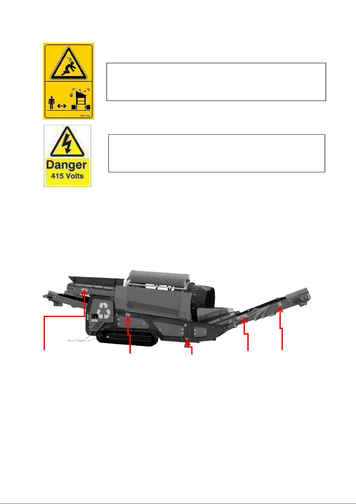
2.4 HAZARD WARNING SIGNS ON THE MACHINE
Hazard warning signs are important features of any equipment. Please take time to
familiarise yourself with their locations on the machine.
ALL SAFETY SIGNS MUST BE CLEARLY VISIBLE, FREE FROM DIRT OR OBSTACLES
BLOCKING THEIR VIEW. ANY MISPLACED OR DAMAGED SAFETY SIGNS MUST BE
REPLACED IMMEDIATELY BEFORE CONTINUING TO OPERATE THE MACHINERY.
SAFETY SIGNS ARE LOCATED ON BOTH SIDES OF THE MACHINE. MAKE YOURSELF
FAMILIAR WITH THEIR LOCATION AND THEIR CORRESPONDING LEVEL OF HAZARD
FALLING MATERIAL HAZARD. NO ONE IS PERMITTED TO STAND
AROUND MACHINERY WHILST MATERIAL IS BEING LOADED. RISK
OF SERIOUS INJURY OR DEATH.
1. ELECTRICAL HAZARD. RISK OF SERIOUS INJURY OR DEATH.
2. WORK ON THE ELECTRICAL SYSTEM MUST ONLY BE
CARRIED OUT BY A QUALIFIED ELECTRICIAN.

13
2.5 SAFETY WARNINGS IN THIS MANUAL
The following safety warnings are used throughout this manual to highlight areas of potential
hazards. Ensure that you make yourself familiar with each sign and their corresponding level
of hazard warning.
The CAUTION sign below indicates a minor or moderate hazard potential. In this situation
care should be taken to avoid the risk otherwise injury to personnel may occur.
!CAUTION
The WARNING sign below indicates a minor or moderate hazard potential. In this situation
care should be taken to avoid the risk otherwise severe injury or death to personnel could
occur.
!WARNING
The DANGER sign below indicates the highest level of hazard potential. In this situation,
extreme care should be taken to avoid the risk otherwise severe injury or death will occur.
!DANGER
2.6 HAZARD ZONE
It is strongly recommended that a hazard or restriction zone should be placed at least 10
metres around the machine. Access to this restricted zone should only be permitted to those
people who meet all the criteria listed below. This procedure, if enforced even when the
machine is shut down, will significantly reduce the potential for all accidents and injuries.
Those permitted to enter the hazard zone should comply with all the following:
(i). Must have authorisation from the plant supervisor to enter the restricted zone.
(ii). Must have read and understood the safety section of this manual
(iii). Must carry out all safety procedures required.
(iv). Must be fully trained and qualified in the work they are carrying out.
(v). Must have experience in working with this type of equipment
(vi). Must be wearing the required “Personal Protective Equipment”.
(vii). Must be accompanied by another person who also meets the criteria.
2.7 PERSONAL PROTECTIVE EQUIPMENT
It is recommended that the minimum personal protection, worn by all persons entering the
hazard zone, should be as follows:
Safety Goggles, Safety Boots, Overalls, Safety Helmet, High Visibility Vest, Gloves, Safety
Harness (when working at heights above 2 Metres) Ear Protection, plus any other on-site
requirements. Note: all protective clothing should be EN/ANSI approved.
2.8 PLANT HAZARDS – WORKING AT HEIGHTS
Where access is required to all areas of the machine which cannot be easily reached from
the ground, an approved lifting platform must be used. If any work or adjustments of any kind
are to be carried out the machine must be shut down and “Locked Out”. Even when using an
approved platform an EN/ANSI Safety Harness must be worn by all personnel working
above heights of 2 metres.

14
2.9 PLANT HAZARDS – ELECTRICS
The equipment detailed in this manual contains voltages from 12 Volts DC to 415 VAC, and
local safety procedures must be strictly adhered to.
Serious injury can result from the misuse or the incorrect installation of electrical equipment
and it is imperative that local electrical regulations are followed when drawing up the site
safe working practices for the machine. As general safe working practice, the following
procedures are given as guidance and should be observed at all times when using or
carrying out electrical work on the machine. Again, these are minimum standards only.
Electrical work must only be carried out by a qualified electrician. What constitutes
qualification is normally controlled by local regulations
In addition, work on the electrical system must only be carried out by individuals with a full
understanding of the electrical system.
Special care should be taken when disconnecting, replacing or charging batteries. Ensure
batteries are disconnected and reconnected correctly. Note: Inadvertent short circuiting
across the battery terminals can cause the battery to explode.
Always disconnect battery leads before carrying out any maintenance to the electrical
system. To avoid damage to electrical components, always isolate the batteries and
electrical system when welding on the machine frame.
Batteries contain sulphuric acid, which can cause severe burns. Avoid contact with the skin,
eyes or clothing. The normal charging produces explosive gases, keep the battery area well
ventilated at all times and do not allow sparks or naked flames nearby.
Regular inspections of all the electrical equipment must be carried out. Any damaged cables,
components or loose connections must be repaired before continuing to operate the
machine. Use only the manufacturer’s genuine replacement parts when performing
maintenance work.
Use only original fuses with the specified current rating
Modification to any part of the electrical system on this machine can cause the machine to
operate in an unsafe manner. No such modifications should be carried out without prior
written permission from Metberg Ltd.
Unauthorised modifications will invalidate the warranty conditions of the electrical system.
2.10 PLANT HAZARDS – HYDRAULICS
The hydraulic supply to the machine will cause death or serious injury or death if proper
procedures are not followed.
(i) Never disconnect any hydraulic circuit without consulting with the manufacturer or your
local dealer.
(ii). Work on the hydraulic system must only be carried out by a qualified technician in
accordance with hydraulic engineering rules.
(iii). Never work on the hydraulic system of any equipment unless you are thoroughly familiar
with system details.
(iv). Do not handle or repair hydraulic equipment with bare hands.
(v). Wear safety goggles for eye protection. If fluid enters skin or eyes, get immediate
medical attention.
(vi). Return controls to neutral position and relieve all pressure in the hydraulic system,
before attempting to disconnect any hydraulic circuit or component.
(vii). Beware of hydraulic oil leaks. Hydraulic fluid under pressure can penetrate the skin or
damage eyes. Fluid leaks under pressure may not be visible. Use a piece of cardboard to
find leaks but do not use bare hand.
(viii). The hydraulic equipment on the machine must be inspected at regular intervals. Loose
connections or damaged, frayed or worn hoses must be repaired immediately.
(ix). Do not exceed safe limits. Never set a pressure relief valve to a pressure higher
than that set at the factory 140 bar 200PSI.

15
2.11 PLANT HAZARDS –MANOEUVRING ON SITE
Make sure that personnel are kept clear when moving the machine on site.
The machine must only be transported with the machine fully lowered.
Avoid manoeuvring the machine over extremely uneven ground as damage may occur.
Make sure that the machine is not manoeuvred on a gradient greater than 3 degrees.
Caution must be exercised when moving machinery on soft or uneven surfaces. It is
recommended that machines are not driven nor turned along a slope. To minimise the risk of
overbalancing, the machines should be only moved vertically up or down shallow slopes.
Before moving the machine, ensure the siren and beacon are working correctly and that
there is no-one on or around the machine or likely to be injured when the machine
commences moving.
Always adjust your speed to an appropriate level when travelling in uneven terrain
When working with or moving the machine, always maintain a safe distance from overhead
electric lines. If work is to be carried out close to overhead lines, the working equipment
must be kept at least the minimum recommended distance away from them. Know and
practice the prescribed safety distances from high voltage cables as governed by local
regulations. If your machine does come into contact with a live cable, the cable must be
isolated before continuing to operate the machine. Warn others against approaching and
touching the machine before the area is made safe. Investigate and report all incidents to the
site manager.
2.12 PLANT HAZARDS –NIP POINTS
Travelling belts and rotating drums and rollers on the machine create potentially serious nip
points. No One should reach into a machine, for whatever reason, while it is running. Always
stop the plant and “Lock Out” when maintenance, repairs or adjustments are required.
Loose clothing, jewellery and long hair should be tied back or removed to avoid
entanglement with the components. Guards are provided at certain high-risk nip points on
the machine. These guards must be kept in place at all times. The machine must NEVER
be operated while any guard is missing or damaged.
2.13 PLANT HAZARDS – MATERIAL FALLING FROM HEIGHTS
Material is discharged off the end of the machine at great heights. Therefore, it is imperative
that no one is permitted to stand or walk within 10 metres of the machine when it is
operating. In some situations, material can roll back down the belt and fall off the side of the
machine. Even when the machine is not operating, personal protective equipment should
always be worn. Loose material can easily fall off the machine even when the belt has
stopped.

16
2.14 SAFETY GUARDS ON THE MACHINE.
Safety guards are important features of the machine. Take time to familiarise yourself with
their locations as shown below.
No.
Description
Qty.
(1).
(2).
(3).
(4).
(5).
Fines conveyor head drum guard
Fines conveyor return roller guard
Oversize conveyor feedboot guard
Oversize conveyor return roller guard
Oversize conveyor head drum guard
2 off
2 off
1 off
2 off
2 off
NEVER OPERATE THE MACHINE WITH ANY GUARD NOT SECURELY IN PLACE AS
THIS CAN CAUSE SERIOUS INJURY OR DEATH
2.15 EMERGENCY STOPS ON THE MACHINE.
Emergency stops are located at both the left side and right side of the machine.
!DANGER
Before removing any guard follow the
“Shut Down” and “Lock Out” procedures.
Replace all missing guards immediately
(1). (3).
(2). (4). (5).
17
!WARNING
Ensure that the following “Lock Out”
procedure is carried out before carrying
out any work on the machine
2.16 “LOCK OUT” PROCEDURE
Each and every time access is required onto or near the machine to carry out work of any
type, regardless of how insignificant it may seem, ensure that a “Lock Out “ procedure is
performed. This procedure is designed to prevent injuries caused by the unexpected start-up
or movement of the machine. These procedures are to be followed every time the machine
is to be cleaned, maintained, adjusted or repaired. When used as intended, Lockout also
protects personnel from energy stored in devices such as springs, accumulators, batteries,
hydraulic systems, etc.
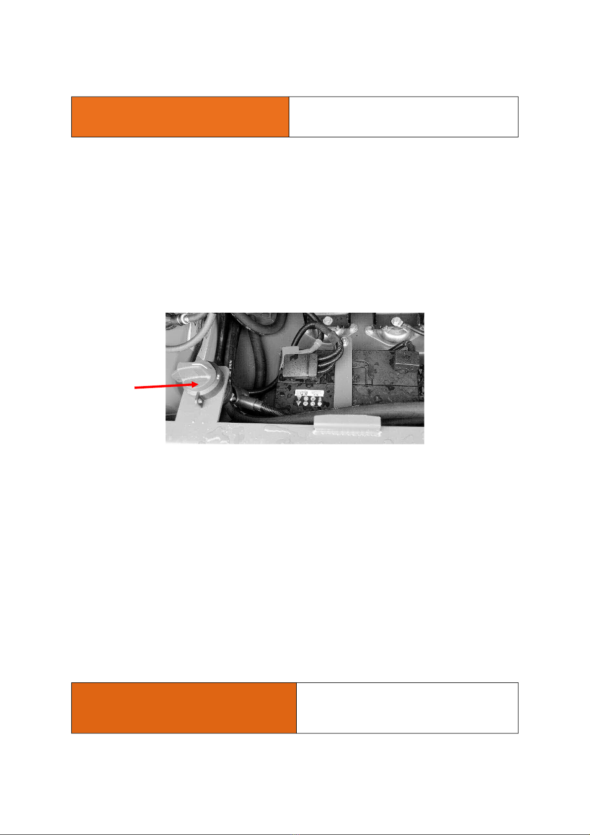
2.16.1 BEFORE CARRYING OUT ANY WORK ON THE MACHINE
(i). Turn off the engine at the starter panel, remove key and put the key in a safe place.
(ii). After 20 seconds, rotate the isolator switch from the “ON” position to the “OFF” position
(iii). Fit a lock out hasp and unique padlock on the main power isolator and keep the key to
make sure no one can remove your lock and turn the power back on.
(iv). Place a tag on the lock that identifies you (by your name, picture or number) as well as
the date and time you locked it out.
(v). Release stored energy from the system, such as hydraulic fluid under pressure, so that
the machine is in a zero energy state.
(vi). Try to start or activate the machine to make sure that the power is off. (Don’t forget to
turn the key off again.)
2.16.2 AFTER CARRYING OUT ANY WORK ON THE MACHINE
(i). Secure the work area by replacing guards and shields, removing blocks, picking up tools
and inspecting the work area.
(ii). Take your lock and tag off the main power isolator.
(iii). If there are no other locks on, turn the main power isolator switch to the ON position
(iv). Warn others before starting the machine.
(v). Start the machine and proceed with your work.
!WARNING
In the case of an accident or failure of
any part of the machine the following
procedure must be carried out
immediately
.
Isolator

18
2.17 EMERGENCY SHUT DOWN PROCEDURE
In an emergency, only stop the machine by pressing an emergency stop button on the
machine. When an emergency stop has been initiated, the ignition switch stays on. Do not
attempt to restart the engine until it is safe to do so.
(i). Press any emergency stop to stop the engine and machine.
(ii). Turn the ignition key to the off (O) position as soon as possible, if safe to do so.
(iii). Remove the ignition key.
(iv). Set the isolator switch to the off position.
(v). When safe, release the emergency stop button(s) by pulling or twisting.
2.18 RESTART PROCEDURE AFTER EMERGENCY SHUT DOWN
Ensure that the problem has been solved and all personnel are clear of the machine. Before
restarting, ensure that all guards are correctly fitted and fully functional. Do not restart until it
is safe to do so.
(i). Release the emergency stop button(s) by pulling or twisting.
(ii). Restart the machine.
2.19 TESTING THE EMERGENCY STOPS
(i). Start the engine.
(ii). Push in an emergency stop button.
(iii). Acknowledge the alarm.
(iv). Re-set the emergency stop by pulling or twisting, depending on the type fitted.
(v). Turn the ignition key to the ‘O’ position.
(vi). Start the engine again.
(vii). Repeat the procedure for all other emergency stops.
!CAUTION
Installation of this equipment must be
carried out by qualified and trained
personnel only. Never install this
equipment on your own.
2.20 SAFETY BEFORE AND DURING SETUP.
(I). Only authorised, trained and qualified personnel should be permitted to install this
equipment.
(ii). Check the area where the machine will be installed for ground stability, height clearance
and access.
(iii). Ensure that the ground is level. Machines installed on uneven ground may not operate
efficiently or may be prone to structural defects due to adverse stresses.
(iv). Ensure that at least two people are present when installation is being carried out.
(v). Ensure that all Personal Protective Equipment is worn. Loose clothing, jewellery and
long hair must be tied back or removed to avoid entanglement in the machinery.
(vi). Never climb onto the machine, especially the belt, to reach areas not accessible from
the ground. Never use unauthorised or unsafe platforms to reach high areas. If ever
necessary, when using an approved access platform an EN/ANSI Safety Harness must be
worn.
(vii). Never walk, stand or work under unsupported equipment during installation.
(viii). During installation ensure that all bolts, fittings and connections are fitted correctly and
tightened appropriately.
(ix). After installation is complete ensure that the machine is fully tested before allowing full
operation.
(x). Before testing the machine ensure that all tools, parts and components have been
removed especially from the belt. Ensure that no one is on or near the machine before
testing.

19
(xi). Test the machine to ensure that it is functioning properly. If problems occur during
testing shut down and adopt the “Lock Out” procedure before attempting to rectify the
problem.
(xii). After testing, shut down the machine and check for loose or missing bolts, washers or
nuts etc.
(xiii). During initial operation, the belt may need to be tracked
.
(xiv). After operating the machine for a few hours shut down and check for any further
problems.
!CAUTION
Only trained, experienced, and qualified
personnel should attempt to operate this
equipment.
2.21 SAFETY BEFORE AND AFTER SETUP
(I). Read and understand all safety hazards and operating procedures before starting the
machine.
(ii). Study all safety and hazard warning signs on the machine.
(iii). Ensure that all Personal Protective Equipment is worn. Loose clothing, jewellery and
long hair must be tied back or removed to avoid entanglement in the machinery.
(iv). Ensure that onlookers and untrained or inexperienced persons are beyond the 10-metre
hazard zone.
(v). Prior to operation check the condition of the machine for worn, broken, missing or
damaged parts or obstructions etc. Ensure that all safety guards and emergency stops are
correctly fitted and in good working order. Carry out daily maintenance required,for
maintenance schedule.
(vi). Before starting walk completely around the machine. Ensure that no one is under it, on
it, or close to it.
(vii) Let other workers and bystanders know you are starting up and do not start until
everyone is outside the 10-metre hazard zone.
(viii). While the machine is running never attempt to reach into or climb onto it for any
reason. Where it is necessary to inspect the machine always shut down and “Lock Out”.
(ix). Never attempt to carry out repairs, maintenance or adjustments of any type, other than
belt alignment, while the machine is running.
(x). Never stand or work beneath the machine while it is being loaded with material.
(xi). Never stand or work beneath the machine while it is discharging material.
(xii). Only use emergency stops in emergency situations or during safety drills.
(xiii). Before shutting down the machine, other than in emergency situations, ensure that all
material has been discharged off the belt. Never leave material on the machine overnight or
for long periods.
!CAUTION
Maintenance should only be carried out by
Authorised and Qualified personnel. Never
carry out maintenance or repair work alone.
2.22 SAFETY BEFORE AND DURING MAINTENANCE
(i). Isolate all electrical supplies to the machine and perform the “Lock Out” procedure before
carrying out any maintenance work.
(ii). Ensure that all moving parts on the machine have stopped before attempting any repairs
or maintenance.
(iii). Ensure that at least two people are present when maintenance or service work is being
carried out.
(iv). Ensure that all Personal Protective Equipment is worn. Loose clothing, jewellery and
long hair must be tied back or removed to avoid entanglement in the machinery.
Table of contents


