Case ALITEC CW12 User manual

ROCK WHEEL
MODELS
CW12 CW18 CW18XTP CW24 CW24XTP
EFFECTIVE SERIAL NO.
MANUAL
*Operation
*Maintenance
*Service
*Parts
M-CW REV H 5/8/03

2
INTRODUCTION
Thank you for your investment in Case/Alitec attachments. We are confident that you
will find that your Case/Alitec attachment is the easiest to operate, safest, most durable,
and most efficient attachment on the market.
Your Case/Alitec attachment is equipped with high performance, heavy duty
components. To ensure that these components operate properly and effectively, this
manual must be followed. If any question regarding the operation or performance of this
attachment exists, contact your Case/Alitec dealer at once.
This manual contains safety instructions, guidelines for efficient operation,
troubleshooting tips, and service and maintenance procedures. When applicable, the
terms “right” and “left” are referenced from a sitting position facing forward in the
loader.
Throughout this manual, information is provided in boxes and highlighted by the word
IMPORTANT. This information should be read carefully. If complied with, it will
improve the operating efficiency of the unit and provide directives that will minimize
costly breakdowns and extend the life of the machine.
This warning symbol appears throughout this manual and indicates
that a safety hazard may exist if the information given is not
properly followed. When the warning signal is encountered in the
manual or on the unit, Be Alert! Your personal safety is involved!
For more copies of this manual or the necessary safety decals,
contact your Case/Alitec dealer.

3
TABLE OF CONTENTS
Page
SAFETY DECALS ............................................................................................................ 3
SAFETY PRECAUTIONS ............................................................................................... 6
MANDATORY SAFETY SHUTDOWN PROCEDURE .............................................. 6
SAFETY ............................................................................................................................. 7
SETUP ................................................................................................................................ 8
OPERATION..................................................................................................................... 9
EXPLODED VIEW-CW ................................................................................................ 12
PARTS LIST-CW............................................................................................................ 13
EXPLODED VIEW - HYDRAULICS .......................................................................... 16
PARTS LIST - HYDRAULICS...................................................................................... 17
MAINTENANCE ............................................................................................................ 18
SERVICE ......................................................................................................................... 19
SPECIFICATIONS ......................................................................................................... 21
HYDRAULIC/ELECTRICAL SCHEMATIC ............................................................. 22
WARRANTY ................................................................................................................... 23
WARRANTY & POLICIES........................................................................................... 24

4
SAFETY DECALS
Keep clear during
operation.
WARNING
PINCH AREA
D0192
This decal indicates possible pinch point
areas on the attachment. Stay clear of
this area during operation. Failure to
observe this warning could result in
serious injury or death. (D0192)
(D0209) NO STEP
(D0404)
WARNING
D0195
FLYING OBJECT
Keep clear during
operation.
HAZARD
This decal indicates the possibility of
objects flying from the attachment during
operation. Stay clear of these areas
during operation. Failure to observe
this warning could result in serious
injury or death. (D0195)
(D0062)

5
(19924)
(54519)

SAFETY
PRECAUTIONS
ACCIDENTS ARE
PREVENTABLE WITH YOUR
HELP
WARNING
BEFORE OPERATING THIS
EQUIPMENT, THE FOLLOWING
SAFETY INFORMATION SHOULD BE
READ AND UNDERSTOOD. IN
ADDITION, EACH INDIVIDUAL
WORKING WITH THE EQUIPMENT
SHOULD BE FAMILIAR WITH THE
SAFETY PRECAUTIONS.
Exercise extreme caution when hitching and
removing the attachment, operating with
other workers present, and servicing the
unit.
Case/Alitec always makes operator safety a
priority when designing machinery.
Exposed moving parts are guarded
whenever possible for safety. However, not
all moving parts can be shielded in order to
ensure proper operation. This operator’s
manual and the safety decals on the machine
provide important safety information and
observed closely. If safety decals become
difficult to read, replace them immediately
(see “Safety Decals”).
MANDATORY
SAFETY
SHUTDOWN
PROCEDURE
BEFORE cleaning, adjusting, lubricating.
or servicing this unit, ALWAYS follow the
MANDATORY SAFETY SHUTDOWN
PROCEDURE:
1. Move the skid steer loader propulsion control
lever to the “neutral” position.
2. Shut off the attachment by shutting off the
auxiliary hydraulic output.
3. Lower the loader lift arms completely and
roll the attachment forward so it is securely
resting on firm ground or the shop floor.
4. Engage the loader park brake.
5. Move the loader throttle to the slow idle
position, shut the engine off, and remove the
ignition key.
6. Keep the key with you at all times when
working on the unit so no one can start the
engine without your knowledge.
WARNING
FAILURE TO FOLLOW THE
PROCEDURES BEFORE
CLEANING, ADJUSTING,
LUBRICATING, OR SERVICING
THIS UNIT COULD LEAD TO
SERIOUS INJURY OR DEATH.

7
SAFETY
A careful operator is the best protection
against accidents. Most accidents involving
operators of industrial equipment are caused
by failure to observe basic safety
precautions. Familiarize yourself with the
safety precautions listed below.
WARNING
THE FOLLOWING PRECAUTIONS
MUST BE OBSERVED FOR THE
SAFETY OF THE OPERATOR
AND/OR SERVICE PERSONNEL.
1. Read and observe all safety information
and decals on the skid steer loader and
attachment BEFORE operating the unit!
(See Safety Decals). In addition,
familiarize yourself with all loader safety
devices and check daily that they are
functioning properly.
2. Refer to the SAFETY section of your
skid loader operator’s manual and
observe all safety recommendations set
forth in that manual.
3. When loading, keep attachment as low to
ramps & trailer as possible.
4. Always lower the loader arms fully
before leaving the skid steer seat.
WARNING
NEVER CRAWL UNDER RAISED
LOADER ARMS.
5. BE SURE to raise the attachment totally
off the ground BEFORE sideshifting.
6. CAREFULLY inspect ALL hydraulic
hoses and connections on a routine basis;
Always use a piece of cardboard when
searching for leaks.
7. BE SURE to exercise the above
MANDATORY SAFETY
SHUTDOWN procedure, BEFORE
proceeding with any work on the
attachment.
WARNING
NEVER USE YOUR HANDS AS
ESCAPING FLUID UNDER PRESSURE
CAN PENETRATE THE SKIN
CAUSING SERIOUS INJURY. IF
HYDRAULIC FLUID DOES
PENETRATE THE SKIN, SEEK
IMMEDIATE MEDICAL ATTENTION
BY A DOCTOR FAMILIAR WITH
THIS TYPE OF INJURY OR
GANGRENE MAY RESULT.
WARNING
NEVER ALLOW HANDS OR FEET
NEAR ANY WORKING PART OF THE
ATTACHMENT UNLESS THE
MANDATORY SAFETY SHUTDOWN
PROCEDURE HAS BEEN
COMPLETED.

8
SETUP
WARNING
READ THIS ENTIRE MANUAL AS
WELL AS THE DECALS ON THE
ATTACHMENT BEFORE
ATTEMPTING ANY MAINTENANCE,
SERVICE, OR SETUP OF THE UNIT.
Although the Case/Alitec Attachment is
supplied fully assembled, some simple
checks should be performed before
operation begins.
Safety Decals
The safety decals existing on the attachment
should be clearly readable and always
followed. The location and description of
the decals is shown in the exploded
diagram. Copies of the decals are shown in
“Safety Decals” section.
Lubrication
All attachment joint grease fittings should
be greased until grease flows out of the
joint.
IMPORTANT
Type of lubricant should be 80-90W gear
lube, with an EP (extreme pressure)
rating of GL-5 minimum.
Hoses / Fittings
Hydraulic fittings are used to connect all
attachment hoses. All fittings should be
tight and free of hydraulic leaks. Hoses
must be free of crimps or cuts that might
result in leakage. Check your attachment
before operation to make sure all hose
routings are kink-free and allow for
maximum movement of all extend,
lift/lower, and/or swing motion required
during normal operation.
Wire Harness
The wiring harness to the electro hydraulic
valve block should be routed to prevent
catching or pinching when sideshifting or
lowering the wheel fully into the ground.
Ensure the wiring harness is routed under
the sideshift frame top angle into the loader
cab to prevent tripping when entering or
exiting the loader.
Wheel Assembly
For proper operation, wheel picks must be
installed in every holder on the wheel.

9
OPERATION
The rock wheel is a hydraulically powered
attachment intended for cutting asphalt or
concrete surfaces. The performance of the
attachment can vary greatly depending upon
how it is used and operated. Therefore, the
recommended operating procedures
contained within this manual should be
followed at all times for maximum
productivity.
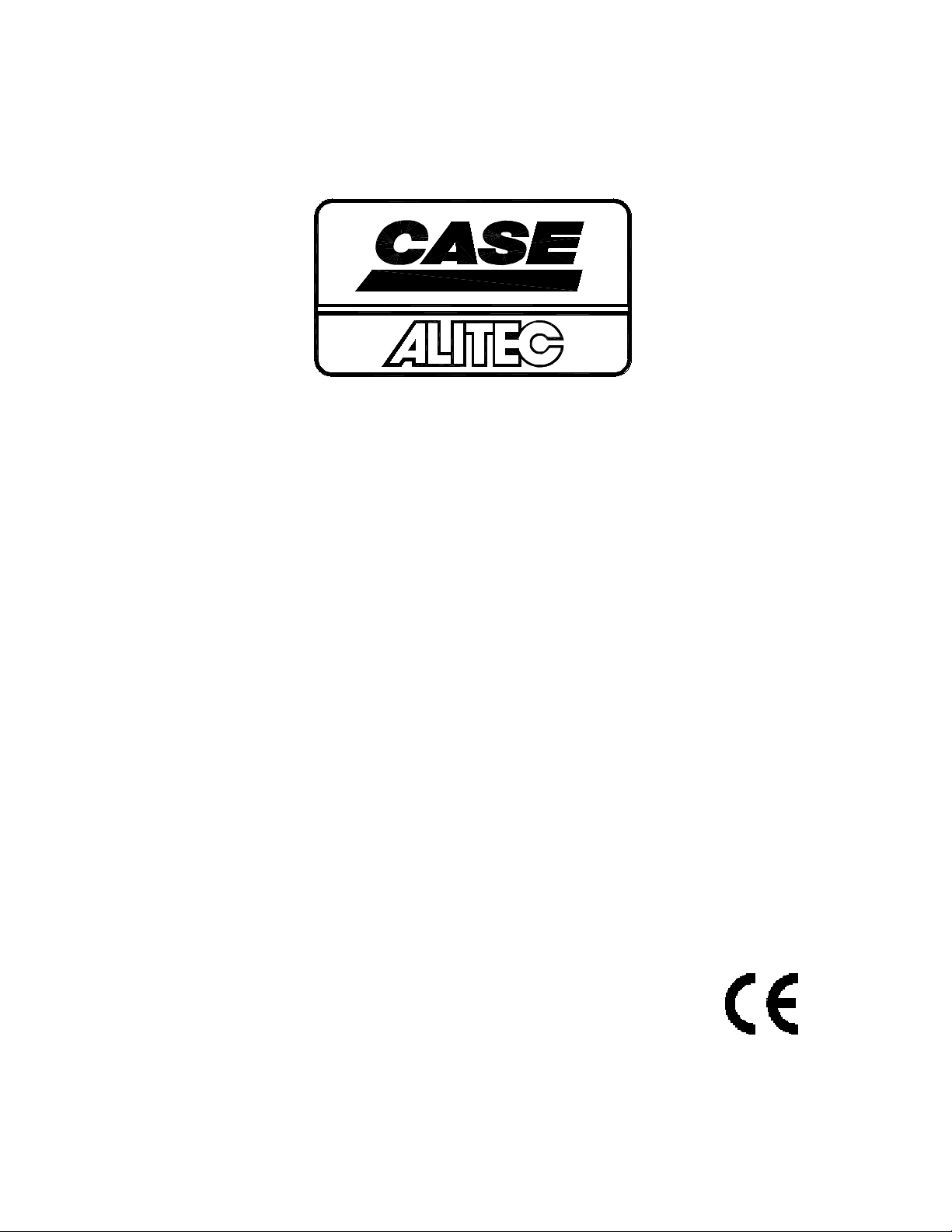
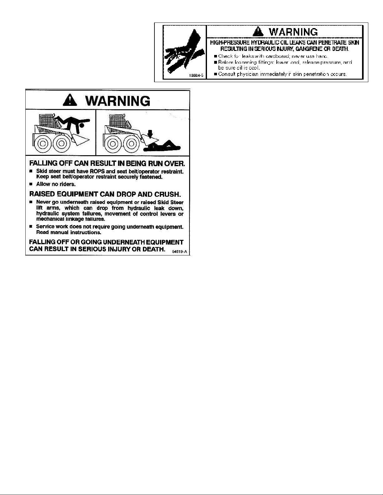
Prior to operating the attachment, read this
entire manual. Follow all safety guidelines
in this manual and safety decals on the unit.
Make sure that all guards, shields, and
decals are in place and in good condition
prior to operation.
As noted in the Case/Alitec literature, the
attachment requires a minimum hydraulic
supply of 25 gallons per minute (100 liters
per minute) at 2000psi (135 bar).
IMPORTANT
Insufficient hydraulic power will result in
poor performance. Check auxiliary high
flow per factory specifications.
Attaching to Loader
To attach the unit to the loader, start the
loader engine and rotate the couplers out.
Pull both couplers levers up to the vertical
position. Move the machine forward and
pick up the attachment. Rotate the
attachment back and push both coupler
levers completely down. Make sure the two
wedges are completely down and engaged.
See operating instructions in the loader
manual.
In attaching the unit to the skid steer, ensure
that all hydraulic hoses are coupled securely
to the quick couplers. Five hoses are to be
connected. Motor pressure, motor return,
motor casedrain, and two high flow
hydraulic hoses.
IMPORTANT
All hoses should be free of kinks, cuts, or
abrasions for safe operation.
To Operate
1. Engage the hydraulic power, set the
depth arm to the proper depth setting and
lower the rock wheel slowly.
2. Actuate the bucket cylinder function for
rollout until the wheel depth pad comes
in contact with the pavement surface.
3. Before advancing the host vehicle, allow
the wheel to operate until it reaches the
desired depth.
IMPORTANT
For most effective operation, the majority of
the weight of the unit should be placed on
the rock wheel with the loader arms fully
lowered.
IMPORTANT
Operating the rock wheel with the loader
arms in the float position will result in
excessive vibration and should be avoided.
4. With the front depth control arm and pad
set for acceptable cutting depth, the
loader function should be used for lifting
or lowering during rock wheel operation.

10
5. Excessive ground speed will stall wheel
rotation. The hydraulic relief valve on
the skid steer will prevent damage from
occurring by diverting all flow from the
wheel motor and the rotation of the rock
wheel will stop. When this occurs,
simply stop or slightly reverse the
forward drive of the host vehicle. For
maximum productivity, the rock wheel
should always be operated at full engine
throttle to ensure that full hydraulic
horsepower is available to the cutting
wheel.
IMPORTANT
The bucket cylinder function should never
be used to lift the wheel when it is stalled
due to the existence of secondary reliefs on
some host vehicle bucket cylinders.
Side Shift Operation
The two auxiliary hoses (See Exploded
Diagram), when connected to the auxiliary
hydraulics of the skid steer, provide
hydraulic power necessary for depth and
sideshift operations. To operate the
sideshift control, set the options switch to
"sideshift" and actuate auxiliary control.
The rock wheel will freely shift on the
sideshift rods. In the event that the direction
of travel does not correspond with the side
of the auxiliary control, simply switch the
sideshift hoses.
Hydraulic Depth Control
To operate the hydraulic depth control, set
the options switch to `depth' and actuate the
auxiliary hydraulics to achieve the desired
depth.


12
EXPLODED VIEW-CW

13
PARTS LIST-CW
ITEM
#
DESCRIPTION PART NUMBER
1 CHASSIS
CW12
CW18
CW24
105626
105628
105630
2 CUTTING WHEEL (INCLUDES PICKS)
2.5” CW12
4.5” CW12
2.5” CW18
4.5” CW18
2.5” CW24
4.5” CW24
6.0” CW24
CONSULT
FACTORY
3 DEPTH CONTROL ARM
CW12
CW18
CW24
06019
06546
100775
4 FOOT PAD 100219
5 FOOT PAD, SIDESHIFT PIN T1033
6 1” SNAP RING M0003
7 SPACER/WASHER BB090
8 SNAP RING M0042
9 GUIDE ARM 06531
10 GUIDE WHEEL BUSHING T1006
11 GUIDE WHEEL T1005
12 PICKS
2.5” CW12 (28)
4.5” CW12 (33)
2.5” CW18 (42)
4.5” CW18 (48)
2.5” CW24 (56)
4.5” CW24 (66)
6.0” CW24 (78)
B1050S
13 PICK HOLDER P0313
14 DISC SPACER 101086
15 GEAR BOX, FAIRFIELD
GEAR BOX, FAIRFIELD (CW18 XT Piston /CW24XT Piston)
BOOT SEAL
OIL SEAL
HC159
HC539
S01-00033
S01-00009
16 MOTOR GASKET M0009
17 MOTOR, SUNSTRAND
MOTOR, SUNSTRAND M35 (CW18XT Piston /CW24XTPiston)
SHAFT SEAL
HC184
HC321
S01-00013
18 WASHER, MOTOR MOUNTING B0820
19 BOLT, MOTOR MOUNTING B0801
20 BOLT, PLANETARY MOUNTING B0901
21 WASHER, PLANETARY MOUNTING B0920
22 NUT, PLANETARY MOUNTING B0915
23 DECAL, PLANETARY LUBE D0042
24 WHEEL 100604

14

15
PARTS LIST-CW (CON’T)
ITEM # DESCRIPTION PART
NUMBER
25 WHEEL BUSHING 101218
26 NUT, WHEEL 34279
27 BOLT, WHEEL B1609
28 DEPTH CYLINDER
CW12
CW18/24
C1401
C2201
29 SIDE SHIFT CYLINDER C2201
30 DEPTH ARM PIN T1028-1
31 CYLINDER MOUNTING PIN T1035-1
32 DECAL, DEPTH (CW12/18)
(CW24)
D0051
D0105
33 DECAL, PINCH POINT D0192
34 DECAL, READ MANUAL D0404
35 FLAP M0039
36 BOLT, WHEEL MOUNTING B1004
37 WASHER, WHEEL MOUNTING B1021
38
39
40
41
42
43
44
45
46
47
48
DECAL
CW12
CW18
CW24
DECAL, CASEDRAIN
DECAL, LIFT POINT
SLIDER BAR
BOLT, 3/8 x 1 ¾-16 GR8 PLT
NUT, 3/8-16 GR8 STOVER LOCK
WASHER, 3/8 FLAT SAE PLT
DECAL, PICK MAINTENANCE
DECAL, BYSTANDERS STAY AWAY
DECAL, HIGH PRESSURE
DECAL, SKID STEER CRUSH
PICK TOOL
D0179
D0180
D0257
D0323
D0158
105303
58428
B0618
21757
D0099
D0062
19924
54519
M0007
MANUAL M-CW

16
HYDRAULICS – DUAL CIRCUIT

17
HYDRAULICS – DUAL CIRCUIT
PARTS LIST
ITEM #
DESCRIPTION
PART #
SEAL LOCK
FITTINGS
1 CYLINDER, 2 X 22 SIDESHIFT C2201
2 CYLINDER, 2 X 14 DEPTH CW12 C1401A1
CYLINDER, 2 X 22 DEPTH CW18/CW24 C2201A1
3 FITTING, 12OM X 12FLM 90°
FITTING, 12OM X 12SLM 90°CW18XTP/CW24XTP
F1001
F1293
4 FITTING, 6OM X 6FLM 90°
FITTING, 6OM X 6SLM 90°CW18XTP/CW24XTP
F1044
F1407
5 FITTING, 6FLF X 6FLM 90°
FITTING, 6SLF X 6SLM 90°CW18XTP/CW24XTP
F1057
F1387
6 FITTING, 10 OM X 6FLM ST
FITTING, 10 OM X 6SLM ST CW18XTP/CW24XTP
F1137
F1465
7 FITTING, 6OM X 6FLM 90°
FITTING, 6OM X 6SLM 90°CW18XTP/CW24XTP
F1071
F1327
8 MOTOR, SUNDSTRAND M46-3013 (THRU SER. NO. 93CW00093)
MOTOR, SUNDSTRAND M35-3004 CW18XTPISTON/CW24XTPISTON
MOTOR, SAUER-DANFOSS M44
HC184
HC321
HC550
9 VALVE ASSEMBLY, 2-STAGE HC230
10 HOSE, #6 X 93” 6FLF X 6FLF R1
HOSE, #6 X 93” 8SLF X 8SLF R1 CW18XTP/CW24XTP
H1087
H1635
11 HOSE, #4 X 60” 6FLF90°X 6FLF R1
HOSE, #4 X 60” 6SLF90°X 6SLF R1 CW18XTP/CW24XTP
H1097
H1624
12 HOSE, #4 X 20” 6FLF X 6FLF R1
HOSE, #4 X 20” 6SLF90°X 6SLF R1 CW18XTP/CW24XTP
H1044
H1609
13 HOSE, #12 X 91” 12FLF X 12FLF R2
HOSE, #12 X 91” 12SLF X 12SLF R2 CW18XTP/CW24XTP
H1138
H1623
14 HOSE, #12 X 91” 12FLF X 12FLF R12
HOSE, #12 X 91” 12SLF X 12SLF 5000PSI CW18XTP/CW24XTP
H1131
H1634
15 HOSE, #4 X 58” 6FLF X 6FLF R1
HOSE, #4 X 58” 6SLF X 6SLF R1 CW18XTP/CW24XTP
H1218
H1625
16 QD, FITTING 5/8” FEMALE PARKER HC545
17 QD, FITTING 5/8” MALE PARKER HC417
18 QD, FITTING 3/8” MALE PARKER HC418
19 QD, FITTING ½” FEMALE PARKER HC546
20 QD, FITTING ½” MALE PARKER HC547
21 FITTING, 12 OM X 12FLM ST F1006
22 FITTING, 8 OM X 6FLM ST F1070
23 FITTING, 10 OM X 6FLM ST F1137

18
MAINTENANCE
Proper maintenance of the attachment will
result in longer life and the more productive
and cost effective operation. There are two
basic categories of maintenance required,
pick/holder replacement and component
lubrication. For proper operation, the picks
should be checked and lubricated daily to
ensure that they can freely rotate in their
holders.
WARNING
BEFORE PERFORMING ANY
MAINTENANCE ON THE UNIT,
PERFORM THE MANDATORY
SAFETY SHUTDOWN PROCEDURE.
Pick/Holder Replacement
As regular use takes place, normal wear of
the carbide picks will occur with the outer
most picks wearing first. The pick tool
included with the rock wheel should be used
to remove the picks from the cast holders. In
the event the pick tool is not available, any
hardened punch or tool allowing access to
the bottom of the holders can be used.
IMPORTANT
Welder must be grounded directly to drum
during pick holder replacement or SEVERE
BEARING DAMAGE WILL RESULT.
WARNING
NEVER DRIVE THE PICK IN BY
STRIKING DIRECTLY ON THE END
OF THE PICK AS THIS CAN CAUSE
THE PICK TO CHIP AND CAUSE
INJURY OR CREATE SMALL STRESS
FRACTURES IN THE PICK
RESULTING IN PREMATURE WEAR.
A length of pipe with a 3/4-1 inch inside
diameter can be placed over the pick to
protect it from a direct hit. Striking a small
piece of wood placed on the pick to absorb
the shock will prevent damage.
WARNING
ALWAYS WEAR SAFETY GLASSES
WHEN PERFORMING THIS
OPERATION. HARDENED TOOLS
AND PICKS CAN SHATTER CAUSING
INJURY.
The factory installed carbide pick chosen
for use is a general purpose pick as the rock
wheel is basically used for concrete and
asphalt cutting applications. Specify
B1050S.
To prevent the picks from seizing in the
holders, the picks should be sprayed with
diesel fuel at the end of each day. This will
break down the asphalt build up in the
holders and prevent premature wear by
allowing the picks to rotate in the holders.
If the pick remains in the holder beyond its
intended replacement point, it reduces the
cutting performance and will not protect the
holder. Inspect the cutting wheel every half

19
hour of operation. Check the picks and
holders for wear. If the picks are worn
enough to indicate slight holder wear,
replace the picks.
Wheel Hardfacing
As the wheel is used, it will be necessary to
hardface the wear points on the wheel and
holders. This process is required on a
repetitive basis. The warranty policy will
not cover damage to the wheel or holders
due to negligence.
Lubrication
Lubricate the grease points daily on all
wheels as well as both sideshift rods and the
depth arm.
The lubricant in the gear case of the
planetary must be changed within the first
50 hours of operation. Thereafter, the
lubricant need only be changed once per
year or every 1000 hours whichever occurs
first.
IMPORTANT
Type of lubricant should be EP90W gear
lube, with an EP (extreme pressure)
rating of GL-5 minimum.
The lubricant can be changed by removing
the drain plug located on the bottom of the
planetary gearbox. Allow lubricant to drain.
Remove level plug, 90°from drain plug.
Refill until oil is at level plug (approx. 40
oz.)
Bolt Torque
Re-torque all wheel bolts after five (5) hours
of operation to 175 ±5 ft. lb.
SERVICE
WARNING
BEFORE SERVICING THIS UNIT,
THE MANDATORY SAFETY
SHUTDOWN PROCEDURE MUST BE
COMPLETED. SEE 'SAFETY"
SECTION.
WARNING
EXERCISE EXTREME CAUTION
DURING THIS OPERATION TO
PREVENT TIPPING OF THE UNIT.
Wheel Removal
1. Attach the rock wheel to the skid loader
and move it to a hard, flat surface. Lower
the loader arms until the attach frame
wheels are firmly in contact with the
ground.
2. Extend the depth foot completely.
3. Shut the skid steer engine off and remove
the key.
WARNING
CHASSIS SHOULD BE USED TO
PREVENT THE WHEEL FROM
TIPPING IN STEPS 4 AND 5.
4. 2.5” WHEEL ONLY - Remove the six
bolts attaching the wheel to the drive
hub. Go to step 6.
5. 4.5" WHEEL ONLY - Loosen the nine
bolts mounting the planetary gear box
to the frame. Remove the six bolts
attaching the wheel to the drive hub.

20
6. Remove the nine planetary mounting
bolts and slide the gearbox out and down
in pilot hole to provide clearance for
wheel removal.
7. Enter the loader and sideshift the
planetary/cutting wheel assembly to the
left to separate the cutting wheel from
the planetary gearbox.
8. Slowly and carefully raise the loader
arms to elevate the chassis just high
enough to provide clearance to roll the
wheel out.
WARNING
CHASSIS SHOULD BE RAISED ONLY
HIGH ENOUGH TO ALLOW THE
WHEEL TO ROLL UNDER THE
FRONT OF THE CHASSIS.
WARNING
IF THE CUTTING WHEEL BECOMES
LODGED BETWEEN THE CUTTING
WHEEL CHASSIS AND THE END OF
THE PLANETARY GEAR BOX, DO
NOT ATTEMPT TO DISLODGE THE
WHEEL WHILE IN THE RAISED
POSITION. NEVER PLACE HANDS
OR ANY PART OF YOUR BODY IN,
AROUND OR UNDER THE WHEEL.
THE WHEEL MAY FALL CAUSING
SERIOUS INJURY.
8. Shut off skidsteer and remove key.
9. While carefully supporting the wheel,
roll it from under the chassis for service.
WARNING
USE EXTREME CAUTION DURING
THIS OPERATION TO PREVENT
PLANETARY FROM TIPPING AND
FALLING.
Planetary Removal
1. Remove the wheel from the attachment
as previously described.
2. Remove the motor by removing the two
motor mounting bolts.
3. Fully support the planetary with hoist
and remove the nine planetary flange
mounting nuts.
4. Carefully slide the planetary from the
rock wheel chassis with a hoist or similar
device rated for more than 250 lbs.
capacity.
Sideshift Cylinder Removal
1. With the attachment on a level surface,
remove both one- inch retaining rings
from cylinder mounting pins.
2. Disconnect both hydraulic hoses.
3. Remove both cylinder mounting pins.
This manual suits for next models
4
Table of contents
Other Case Construction Equipment manuals

Case
Case TX130--30 Instruction manual

Case
Case 2050M User manual

Case
Case CRAWLER DOZER 650L TIER3 User manual

Case
Case SV208D User manual

Case
Case DV209C User manual

Case
Case 570NXT User manual

Case
Case Tier 2 User manual

Case
Case 850M User manual

Case
Case TX130-40 turbo User manual

Case
Case Titan 3030 User manual