Trio ER450 User manual

User Manual
E Series Data Radio
www.trio.com.au
ER450 Remote Data Radio
EB450 Base Station
EH450 Hot Stand-by Base Station
Issue 4: May 2003

Page 2
E Series Data Radio – User Manual
© Copyright 2002 Trio DataCom Pty. Ltd.
Warranty
AllequipmentsuppliedbyTrioDataComPty.Ltd.iswarrantedagainst
faultyworkmanshipandpartsforaperiodoftwelve(12)monthsfrom
thedateofdeliverytothecustomer.DuringthewarrantyperiodTrio
DataComPty.Ltd.shall,atitsoption,repairorreplacefaultypartsor
equipmentprovidedthefaulthasnotbeencausedbymisuse,
accident,deliberatedamage,abnormalatmosphere,liquidimmersion
orlightningdischarge;orwhereattemptshavebeenmadeby
unauthorisedpersonstorepairormodifytheequipment.
Thewarrantydoesnotcovermodificationstosoftware.Allequipment
forrepairunderwarrantymustbereturnedfreightpaidtoTrioDataCom
Pty.Ltd.ortosuchotherplaceasTrioDataComPty.Ltd.shall
nominate.Followingrepairorreplacementtheequipmentshallbe
returnedtothecustomerfreightforward.Ifitisnotpossibleduetothe
natureoftheequipmentforittobereturnedtoTrioDataComPty.Ltd.,
thensuchexpensesasmaybeincurredbyTrioDataComPty.Ltd.in
servicingtheequipmentinsitushallbechargeabletothecustomer.
Whenequipmentforrepairdoesnotqualifyforrepairorreplacement
underwarranty,repairsshallbeperformedattheprevailingcostsfor
partsandlabour.UndernocircumstancesshallTrioDataComPty.
Ltd.’sliabilityextendbeyondtheabovenorshallTrioDataComPty.
Ltd.,itsprincipals,servantsoragentsbeliablefortheconsequential
damagescausedbythefailureormalfunctionofanyequipment.
Important otice
© Copyright 2002 Trio DataCom Pty. Ltd. All Rights Reserved
ThismanualcoverstheoperationoftheESeriesofDigitalData
Radios.Specificationsdescribedaretypicalonlyandaresubjectto
normalmanufacturingandservicetolerances.
TrioDataComPtyLtdreservestherighttomodifytheequipment,its
specificationorthismanualwithoutpriornotice,intheinterestof
improving performance, reliability or servicing. At the time of
publication all data is correct for the operation of the equipment at
the voltage and/or temperature referred to. Performance data
indicates typical values related to the particular product.
This manual is copyright by Trio DataCom Pty Ltd. All rights
reserved. No part of the documentation or the information supplied
may be divulged to any third party without the express written
permission of Trio DataCom Pty Ltd.
Same are proprietary to Trio DataCom Pty Ltd and are supplied for
the purposes referred to in the accompanying documentation and
must not be used for any other purpose. All such information
remains the property of Trio DataCom Pty Ltd and may not be
reproduced, copied, stored on or transferred to any other media or
used or distributed in any way save for the express purposes for
which it is supplied.
Products offered may contain software which is proprietary to Trio
DataCom Pty Ltd. However, the offer of supply of these products
and services does not include or infer any transfer of ownership of
such proprietary information and as such reproduction or reuse
without the express permission in writing from Trio DataCom Pty
Ltd is forbidden. Permission may be applied for by contacting Trio
DataCom Pty Ltd in writing.
Part A - Preface
!
Warning :- RF Exposure
Theradioequipmentdescribedinthisusermanualemitslowlevel
radiofrequencyenergy.Theconcentratedenergymayposeahealth
hazarddependingonthetypeofantennaused.Inthecaseofanon-
directionalantennadonotallowpeopletocomewithin0.5metresof
theantennawhenthetransmitterisoperating.Inthecaseofa
directionalantennadonotallowpeopletocomewithin6metresofthe
antennawhenthetransmitterisoperating.
Related Products
ER450 Remote Data Radio
EB450Base/RepeaterStation
EH450HotStand-byBaseStation
Other Related Documentation
and Products
Quick Start Guide
TVIEW+ Management Suite
Digital Orderwire Voice Module (EDOVM)
StreamRouter/Multiplexer (95MSR)
Revision History
Issue1 July2002 IntitialRelease
Issue2 August2002 AddedEH450QuickStartSection
andSpecificationsSection
Issue3 November2002 MajorEditstoTVIEWandminoredits
toquickstartsections.
Part A Preface

Page 3
E Series Data Radio – User Manual
© Copyright 2002 Trio DataCom Pty. Ltd.
Contents
Contents
SECTIO 1
Part A Preface 2
Warranty 2
ImportantNotice 2
RelatedProducts 2
OtherRelatedDocumentationandProducts 2
RevisionHistory 2
Part B E Series Overview 4
DefinitionofESeriesDataRadio 4
ESeries Product Range 4
ESeries–FeaturesandBenefits 4
ModelNumber Codes 6
StandardAccessories 7
Part C Applications 8
GenericConnectivity 8
ApplicationDetail 8
SystemsArchitecture 9
Part D System Planning and Design 11
UnderstandingRFPathRequirements 11
Examples of Predictive Path Modelling 12
SelectingAntennas 14
DataConnectivity 15
Power Supply and Environmental Considerations 18
PhysicalDimensionsof theRemoteData Radio 19
PhysicalDimensionsof theBaseStation 20
PhysicalDimensions ofthe Hot StandbyBase Station 21
Part E Getting Started 22
ER450QuickStartGuide 22
EB450QuickStartGuide 28
EH450QuickStartGuide 31
Part F - Operational Features 36
Multistreamfunctionality(SIDcodes) 36
Collision Avoidance (digital and RFCD based) 36
DigipeaterOperation 36
TVIEW+ Diagnostics 36
Part G Commissioning 37
Power-up 37
LEDIndicators 37
DataTransferIndications 37
Antenna Alignment and RSSI Testing 37
LinkEstablishmentandBERTesting 37
VSWR Testing 37
Part H Maintenance 38
RoutineMaintenanceConsiderations 38
SECTIO 2
Part I TVIEW+ Management Suite -
Programmer 40
Introduction 40
Installation 40
TVIEW+ Front Panel 41
Programmer 41
Part J TVIEW+ Management Suite -
Remote Diagnostics & etwork
Controller 53
Introduction 53
SystemDescription 53
OperatingInstructions 55
Interpreting Poll Results 66
Part K Appendices 67
Appendix A- Application and Technical Notes 67
Appendix B - Slip Protocol 67
AppendixC- Firmware Updates 68
Part L Specifications 69
Part M Support Options 70
WebsiteInformation 70
E-mail Technical Support 70
Telephone Technical Support 70
ContactingtheServiceDepartment 70
Page 4
E Series Data Radio – User Manual
© Copyright 2002 Trio DataCom Pty. Ltd.
Part B E Series Overview
Definition of E Series Data Radio
TheESeriesisarangeofwirelessmodemsdesignedforthe
transmission of data communications for SCADA, telemetry, and
any other information and control applications that utilise ASCII
messaging techniques. The E Series uses advanced “digital”
modulation and signal processing techniques to achieve
exceptionally high data throughput efficiency using traditional
licensed narrow band radio channels.
The products are available in many frequency band and regulatory
formats to suit spectrum bandplans in various continental regions.
The range is designed for both fixed point to point (PTP), and
multiple address (MAS) or point to multipoint (PMP) systems.
E Series Product Range
The E Series range consists of the basic half duplex “Remote”
radio modem, an extended feature full duplex Remote radio
modem, and ruggedised Base Station variants, including an
optional Hot Standby controller to control two base station units in
a redundant configuration.
Frequency band variants are indicated by the band prefix and
modelnumbering.(SeeModelNumberCodes)
Part B E Series Overview
E Series Features and Benefits
Common Features and Benefits of the E
Series Data Radio
• Up to 19200bps over-air data rates using programmable
DSP based advanced modulation schemes
• Designed to various International regulatory requirements
including FCC, ETSI and ACA
• Superiorreceiversensitivity
• Fastdataturnaroundtime<10mS
• Flashupgrade-ablefirmware–insuranceagainstobsolescence
• Multi-functionbi-colourTx/RxdataLEDSshowingPortactivity
(breakoutboxstyle), as well as LEDs indicating Tx, Rx, RF
Signal,DataSynchronisationandDCPowerstatusofthe
radio
• RuggedNtypeantennaconnectorsonallequipment
• Hightemperaturetransmitterfoldbackprotection
• Twoindependentconfigurabledataportsandseparatesystem
port
• Higherportspeedstosupportincreasedair-rate(upto
76800bpsonPortAand38400bpsonPortB)
• Independentsystemportforinterruptionfreeprogrammingand
diagnostics(inadditiontotwo(2)userports)
• 9600bpsin12.5kHzradiochannelswithETSIspecifications
• Remoteover-the-airconfigurationofanyradiofromanylocation
• Multistream™simultaneousdatastreamsallowsformultiple
vendordevices/protocolstobetransportedontheoneradio
network
• Flexibledatastreamroutingandsteeringprovidingoptimum
radiochannelefficiency–complexdataradiosystemscanbe
implementedwithfewerradiochannels
• Theabilitytoduplicatedatastreams–thatis,decodethesame
off-airdatatotwoseparateports.
• Multi-functionradiocapableofdroppingoffonestreamtoaport
andforwardonorrepeat(storeandforward)thesameorother
data.
• Stand-aloneinternalstoreandforwardoperation–bufferedstore
andforwardoperationevenintheERremoteunits
• UniqueintegratedC/DSMAcollisionavoidancetechnology
permitssimultaneouspollingandspontaneousreporting
operationinthesamesystem
• Digitalreceiverfrequencytrackingforlongtermdatareliability
• Networkwidenonintrusivediagnosticswhichruns
simultaneouslywiththeapplication
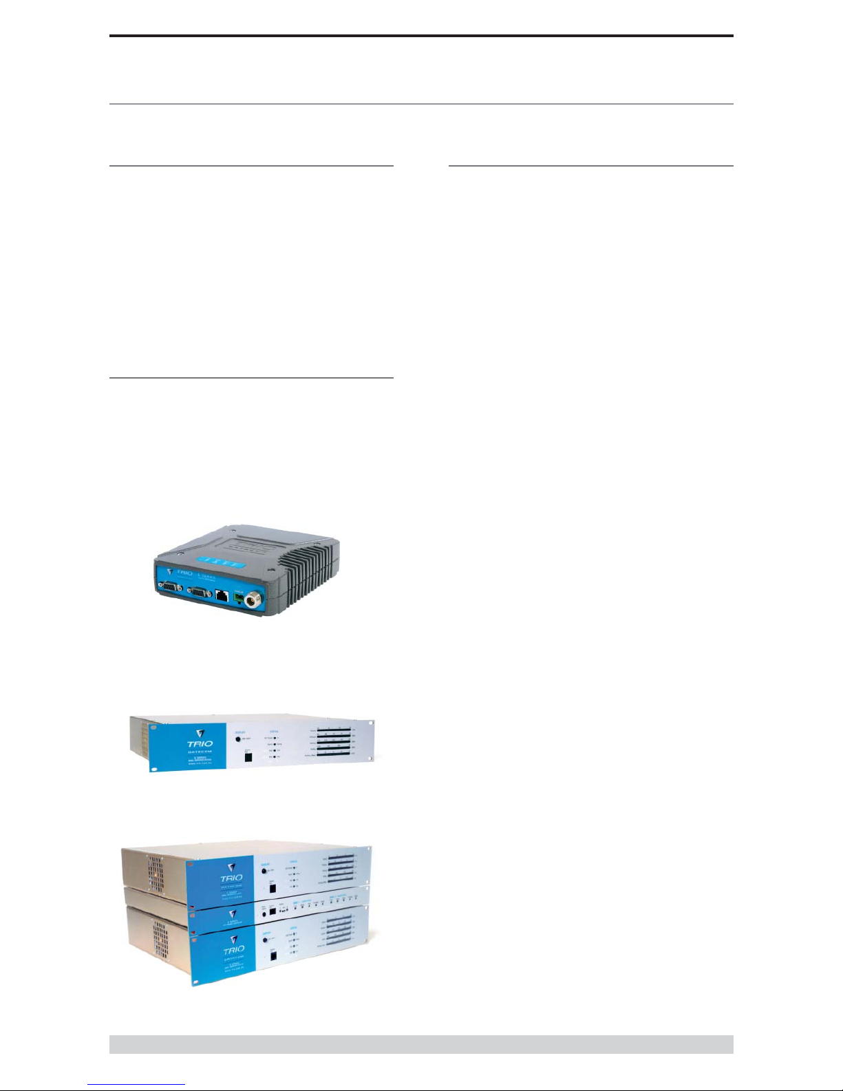
ER450 Remote Radio
EB450 Base / Repeater Station
EH450 Hot Standby Base Station

Page 5
E Series Data Radio – User Manual
© Copyright 2002 Trio DataCom Pty. Ltd.
Part B E Series Overview
• Networkwidediagnosticsinterrogationwhichcanbe
performedfromanywhereinthesystemincludinganyremote
site
• Diagnosticswillrouteitswaytoanyremoteorbase/repeater
siteregardlessofhowmanybase/repeaterstationsare
interconnected
• FullrangeofadvancedfeaturesavailablewithinNetwork
ManagementandRemoteDiagnosticspackage–BERtesting,
trending,channeloccupancy,client/serveroperation,etc.
• Onboardmemoryforimprovinguserdatalatency–increased
userinterfacespeeds
• FullCRCerrorcheckeddata–noerroneousdatadueto
squelchtailsorheaders
• RadioutilisesworldstandardHDLCasitstransportation
protocol
• VariousflowcontrolandPTTcontrolmechanisms
• ConfigurablebackwardcompatibilitywithexistingDSeries
modulationschemeforusewithinexistingnetworks
• Digitalpluginorderwireoptionforcommissioningand
occasionalvoicecommunicationswithouttheneedtoinhibit
usersapplicationdata
Features and Benefits of ER450 Remote
Data Radio
• Optionalfullduplexcapableremote–separateTxandRxports
forconnectiontoanexternalduplexer
• Newcompactandruggeddiecastcasewithinbuiltheatsink
• Lowpowerconsumptionwithvarioussleepmodes
• RuggedNtypeantennaconnectors
• In-linepowersupplyfuses
• DataPort“breakoutbox”styleflowLEDsforeasier
troubleshooting
Features and Benefits of EB450 Standard
Base / Repeater Station
• Competitivelypricedhighperformancebase
• Incorporatesarugged5Wpoweramplifiermodule
• Externalinputforhigherstability10MHzreference–GPS
derived
Features and Benefits of EH450 Hot Standby
Base / Repeater Station
• Individualandidenticalbasestationswithseparatecontrollogic
changeoverpanel
• ALLmodulesarehotswapablewithoutanyuserdowntime
• Flexibleantennaoptions–single,separateTx&Rx,twoTx
and two Rx
• Increased sensitivity with receiver pre-amplifier
• Bothon-lineandoff-lineunitsmonitoredregardlessofactive
status
• Externalinputforhigherstability10MHzreference–GPS
derived
Page 6
E Series Data Radio – User Manual
© Copyright 2002 Trio DataCom Pty. Ltd.
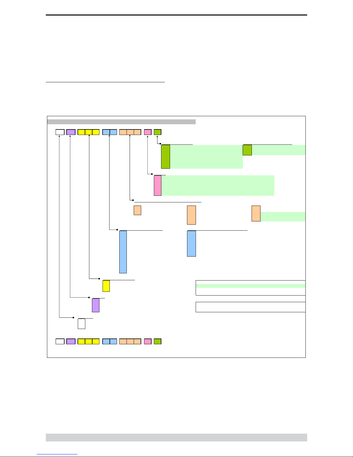
Model umber Codes
D, E & S Series Data Radios - Part Number Matrix = Tyxxx-aabbb-cd
T y xxx-aa bbb-cd
Options - Base Stations* Options - Remote Antenna Connector*
0= No Options 0= No Options (Standard)
1= 450MHz Band Reject
[DUPLX450BR]
N= N Connector (D Series only)
2= 450MHz Band Reject
(<9MHz split)[DUPLX450BR/5]
S= SMA Connector (SR450 only)
3= 450MHz Band Pass
[DUPLX450BP]
4= 900MHz Band Reject
[DUPLX900BR]
5= 900MHz Band Pass
[DUPLX900BP]
6= 900MHz Band Pass
(76MHz split)[DUPLX852/930]
Note: Specify Internally or Externally fitted. Externally fittered duplexes require feeder tails.
Options*
0= No Options
D= Diagnostics - [DIAGS/D, DIAGS/DH, DIAGS/E or DIAGS/EH] (D & E Series Only)
H= Extended Temp Option [HITEMP]
N= Remote Fitted into NEMA Enclosure [NEMA 4/R]
F= Full Duplex Operation [ERFD450] (ER450 only)
X= Full Duplex Operation [ERFD450 & DIAGS/E] (ER450 only)
RF Channel Data Rate & Bandwidth (Internal Modem
)
D Series E Series
A01 = ACA 4800bps in 12.5kHz A01 = ACA 4800
#
/ 9600bps in 12.5Hz 001 = 12.5kHz (No Modem Fitted)
A02 = ACA 9600bps in 25kHz A02 = ACA 9600
#
/ 19k2bps in 25kHz 002 = 25kHz (No Modem Fitted)
F01 = FCC 9600bps in 12.5kHz F01 = FCC 9600
#
/ 9600bps in 12.5kHz 241 = 2400bps in 12.5kHz [24SR]*
F02 = FCC 19k2bps in 25kHz 242 = 2400bps in 25kHz [24SR]*
E01 = ETSI 9600bps in 12.5kHz 482 = 4800bps in 25kHz [48SR]*
E02 = ETSI 19k2bps in 25kHz
Frequency (200 & 400 MHz range) Frequency (900 MHz range) (D & S Series Only)
39 = 208 to 240MHz (Tx & Rx) 07 = (Tx) 847 to 857MHz (Rx) 923 to 933MHz (D Series only, 1W Full Duplex)
50 = 403 to 417MHz (Tx & Rx) 10 = (Tx) 848 to 858MHz (Rx) 920 to 934MHz
58 = (Tx) 406 to 421MHz (Rx) 415 to 430MHz 06 = (Tx) 923 to 933MHz (Rx) 847 to 857MHz (D Series only, 1W Full Duplex)
59 = (Tx) 415 to 430MHz (Rx) 406 to 421MHz 11 = (Tx) 920 to 934MHz (Rx) 848 to 858MHz
56 = 418 to 435MHz (Tx & Rx) 12 = 855 to 860MHz (Tx & Rx)
57 = 428 to 443MHz (Tx & Rx) 14 = (Tx) 925 to 943MHz (Rx) 906 to 924MHz
55 = 436 to 450MHz (Tx & Rx) 15 = (Tx) 904 to 922MHz (Rx) 925 to 943MHz
51 = 450 to 465MHz (Tx & Rx) 16 = 924 to 944MHz (Tx & Rx)
52 = 465 to 480MHz (Tx & Rx)
53 = 480 to 494MHz (Tx & Rx) Note: Other frequency bands available upon request.
54 = 505 to 518MHz (Tx & Rx)
27 = (Tx) 511 to 515MHz (Rx) 501 to 505MHz
48 = 395 to 406MHz (Tx & Rx)
Generic Frequency Band
200 = 208 to 245MHz (D & S Series only) NOTES:
450 = 400 to 518MHz (E & S Series only) * Additional charges apply. Must be ordered seperately. Please refer to price list.
900 = 800 to 960MHz (D & S Series only)
#
Provides compatibility with D Series radio
Items in [ ] parenthesis refer to actual Trio part numbers
Unit Type
R= Remote Station
B= Base / Repeater Station Standards: ACA - Australian Communications Authority
S= Standard Base / Repeater Station (D Series Only) FCC - Federal Communications Commission
H= Hot Standby Base / Repeater (D & E Series Only) ETSI - European Telcommunication Standards Institute
Model Type
D= D Series Family
E= E Series Family
S= S Series Famil
y
Example:
E R 450-51 A02-D0
The above example specifies: E Series, Remote Radio, generic 450MHz band, with a specific frequency of 450MHz to 465MHz,
a 96/19.2kbps modem, with a bandwidth of 25kHz, diagnostics and standard N type connector.
Version: 11/02
S Series

Page 7
E Series Data Radio – User Manual
© Copyright 2002 Trio DataCom Pty. Ltd.
Part B E Series Overview
Part Number Description
Duplexers
DUPLX450BR Duplexer BAND REJECT 400-520 MHz for use
with Base / Repeater / Links. For Tx / Rx
frequency splits >9MHz. (Fitted Externally for a
Link, Intenally or Externally for Base / Repeater)
DUPLX450BR/5 Duplexer BAND REJECT 400-520 MHz for use
with Base / Repeater / Links. For Tx / Rx
frequency splits <9MHz. (Fitted Externally for a
Link, Intenally or Externally for Base / Repeater)
DUPLX450BP Duplexer PSEUDO BAND PASS Cavity 400-
520 MHz for External use with Base / Repeater
/ Links.
Notes:
1. Frequencies must be specified at time of order.
2. Interconnecting (Feeder Tail) cables must be ordered
separately for Externally fitted Duplexers.
Antennas
ANT450/9A Antenna Yagi 6 Element 9dBd Aluminium 400-
520 MHz c/w mtg clamps
ANT450/9S Antenna Yagi 6 Element 9dBd S/Steel 400-520
MHz c/w mtg clamps
ANT450/13A Antenna Yagi15 Element 13dBd Aluminium 400-
520 MHz c/w mtg clamps.
ANT450/13S Antenna Yagi 15 Element 13dBd S/Steel 400-
520 MHz c/w mtg clamps.
ANTOMNI/4 Antenna Omni-directional Unity Gain Side
Mount Dipole 400-520 MHz c/w galv. clamp
ANT450/D Antenna Omni-directional Unity Gain Ground
Independant Dipole 400-520 MHz c/w 3m
cable, mounting bracket & BNC connector
ANT450/6OM Antenna Omni-directional 6dBd 400-520 MHz
c/w mtg clamps
ANT450/9OM Antenna Omni-directional 9dBd 400-520 MHz c/
w mtg clamps
Note:
1. Frequencies must be specified at time of order.
Power Supplies
PS13V82A Power Supply 13.8V 2A 240VAC
PS13V810A Power Supply Switch Mode 240VAC 13.8V 10A
for Base Stations – Battery Charge Capability
Part Number Description
RF Cables and Accessories
NM/NM/TL Feeder Tail - N Male to N Type Male 50cm fully
sweep tested
NM/NM/TLL Feeder Tail - N Male to N Type Male 1 metre
fully sweep tested
RFCAB5M 5.0m RG-58 type Antenna Feeder Cable
terminated with N type Male Connectors
RFCAB5M2 5.0m RG-213 type Antenna Feeder Cable
terminated with N type Male Connectors
RFCAB10M 10.0m RG-213 type Antenna Feeder Cable
terminated with N type Male Connectors
RFCAB20M 20.0m RG-213 type Antenna Feeder Cable
terminated with N type Male Connectors
RFCAB20M4 20.0m LDF4-50 type (1/2" foam dialectric)
Antenna Feeder Cable terminated with N type
Male Connectors
LGHTARRST Lightning Surge Arrestor In-line N Female to N
Female
Multiplexers
95MSR/6 Multiplexer/Stream Router – 6 Port with RS-232
I/faces and Manual
95MSR/9 Multiplexer/Stream Router – 9 Port with RS-232
I/faces and Manual
etwork Management Diagnostics
DIAGS/E Network Management and Remote Diagnostics
Facilities per Radio – E Series
DIAGS/EH Network Management and Remote Diagnostics
Facilities – E Series for EH450
Software
TVIEW+ Configuration, Network Management and
Remote Diagnostics Software
Other
NEMA 4 /R Stainless Steel Enclosure for Remote Site
Equipment.Size 600mm (h) x 600mm (d) x
580mm (w) – Room for Third Party RTU / PLC
equip. (Approx. 400(h) x 600(d) x 580mm(w)
HITEMP Extended Temperature Option for S, D and E
Series Radios -30 to +70C
EDOVM Digital Order Wire Voice Module
ERFD450 ER450…. Conversion to Full Duplex Operation
(N Type – Tx Port, SMA - Type Rx Port)
Note:Requiresexternalduplexer
ERFDTRAY 19"RackTrayforMountingofER450FullDuplex
RadioandExternalBandRejectDuplexer
Standard Accessories

Page 8
E Series Data Radio – User Manual
© Copyright 2002 Trio DataCom Pty. Ltd.
Part C Applications
Part C Applications
Generic Connectivity
The E Series has been designed for SCADA and telemetry
applications, and any other applications that use an ASCII
communications protocol, and which connect physically using the
RS232 interface standard (although converters can be used to
adapt other interfaces such as RS422/485, RS530/V35, G703 etc).
Any protocol that can be displayed using a PC based terminal
program operating via a serial comm port is suitable for
transmission by the E Series radio modems.
An ASCII protocol is any that consists of message strings formed
from ASCII characters, that being defined as a 10 or 11 bit block
including start and stop bits, 7 or 8 data bits and optional parity
bit(s). Port set-up dialog that includes the expressions “N,8,1”, or
E,7,2” or similar indicate an ASCII protocol.
Most of the dominant telemetry industry suppliers utilise proprietary
ASCII protocols, and also common “open standard” industry
protocols such as DNP3, MODBUS, TCP/IP, and PPP. These are
all ASCII. based protocols.
Industries and Applications
The E Series products are widely used in point-to-point and point-
to-multipoint (multiple access) applications for remote
interconnection of PLC’s, RTU’s, dataloggers, and other data
monitoring and control devices including specialist utility devices
(such as powerline ACR’s). In addition, other applications such as
area wide security and alarm systems, public information systems
(traffic flow and public signage systems) and environmental
monitoring systems.
Application Detail
SCADA Systems
This is where one or more centralised control sites are used to
monitor and control remote field devices over wide areas.
Examples include regional utilities monitoring and controlling
networks over entire shires or a greater city metropolis’. Industry
sectors include energy utilities (gas and electricity distribution),
water and sewerage utilities, and catchment and environment
groups (rivers, dams, and catchment management authorities).
Telemetry Systems
Dedicated telemetry control systems interconnecting sequential
devices where cabling is not practical or distances are
considerable.
Examples include ore conveyor or slurry pipeline systems, simple
water systems (pump and reservoir interlinking), broadcast industry
(linking studio to transmitter) etc.
Information Systems
Public Information systems such as freeway vehicle flow and travel
time monitoring, and feedback signage, parking signage systems,
meteorological stations etc.
Page 9
E Series Data Radio – User Manual
© Copyright 2002 Trio DataCom Pty. Ltd.
Part C Applications
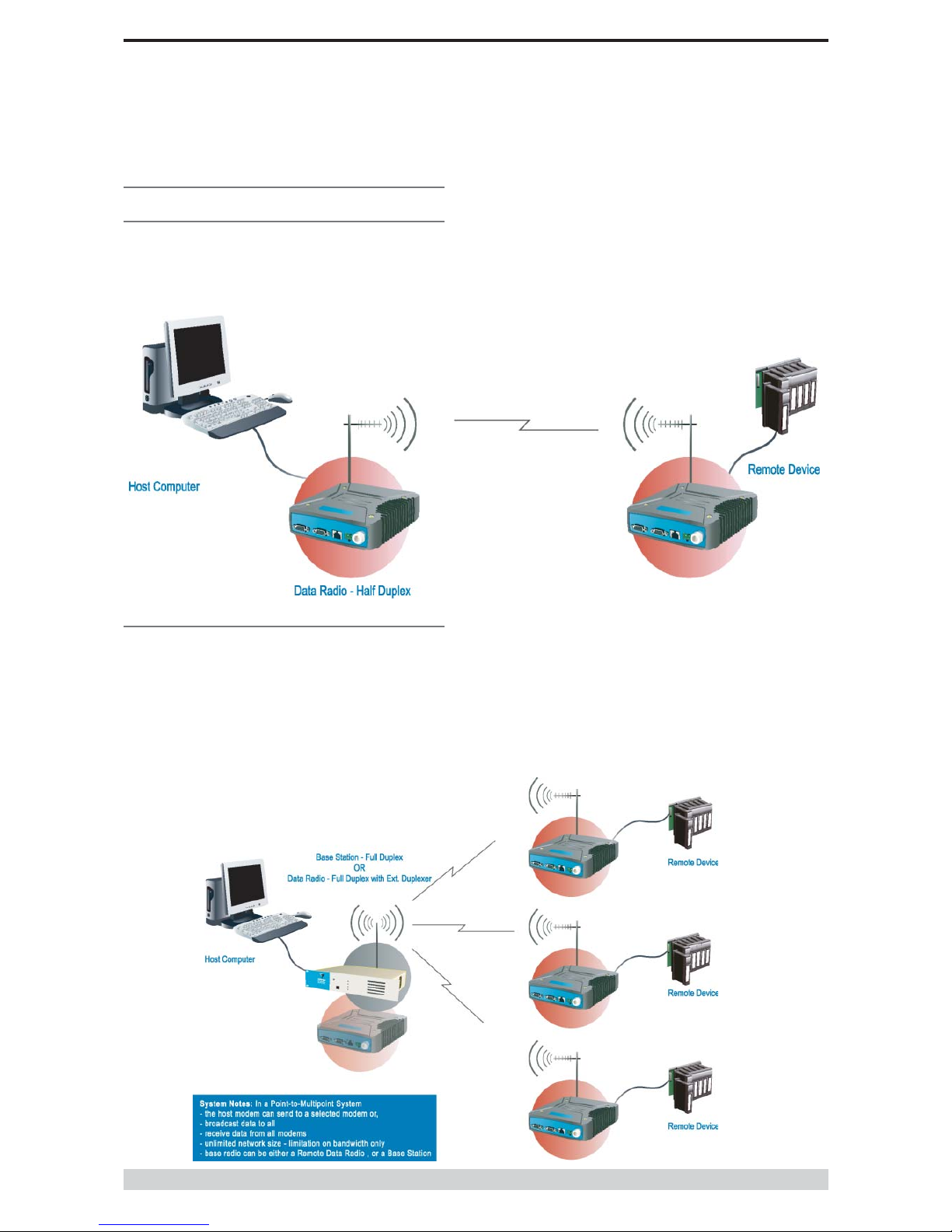
Systems Architecture
Point-to-Point
This simple system architecture provides a virtual connection
between the two points, similar to a cable. Dependant of the
hardware chosen, it is possible to provide a full duplex connection
(i.e. data transfer in both directions simultaneously) if required.
Point-to-Multipoint Systems
In a multiple access radio system, messages can be broadcast
from one (master) site to all others, using a half duplex radio
system, or from any site to all others, using a simplex radio
channel.
Half duplex systems often utilise a full duplex master, to make the
system simpler, and to operate faster.
Ineithercase,itwillbenecessaryfortheapplicationtosupportan
addressing system, since the master needs to be able to select
which remote device it wishes to communicate to. Normally, the
radio system is allowed to operate “transparently”, allowing the
application’s protocol to provide the addressing, and thus control
the traffic. Where the application layer does not provide the
addressing, the E Series can provide it using SID codes™. (See
PartF-OperationalFeatures)

Page 10
E Series Data Radio – User Manual
© Copyright 2002 Trio DataCom Pty. Ltd.
Part C Applications
Digipeater Systems
This configuration is used where all sites are required to
communicate via a repeater site. A repeater site is used because it
has a position and/or height advantage and thus provides superior
or extended RF coverage. The radio modem at the repeater does
not have to be physically connected to the application’s master
site.Informationfromtheapplication’smasteristransmittedtothe
repeater via radio, and the repeater then relays this information to
the other field sites. In this scenario, the repeater is the master
from an RF point of view, and the application master is effectively a
“remote” from an RF point of view, even though it is controlling the
data transfer on the system.
Store and Forward Systems
Store and forward is used as a way of extending RF coverage by
repeating data messages from one site to another.
Thiscanbedonegloballyusingtheinbuiltdatarepeatingfunctions,or
selectivelyusingintelligentaddressbasedroutingfeaturesavailablein
somePLC/RTUprotocols.
In this case it is necessary for all units on the system to operate in
half duplex mode (only key-up when transmitting data), so that
each site is free to hear received signals from more than one
source.

Page 11
E Series Data Radio – User Manual
© Copyright 2002 Trio DataCom Pty. Ltd.
Part D System Planning and Design
Part D System Planning and Design
Understanding RF Path
Requirements
A radio modem needs a minimum amount of received RF signal to
operate reliably and provide adequate data throughput.
In most cases, spectrum regulatory authorities will also define or
limit the amount of signal that can be transmitted, and the
transmitted power will decay with distance and other factors, as it
moves away from the transmitting antenna.
It follows, therefore, that for a given transmission level, there will be
a finite distance at which a receiver can operate reliably with
respect to the transmitter.
Apart from signal loss due to distance, other factors that will decay
a signal include obstructions (hills, buildings, foliage), horizon
(effectively the bulge between two points on the earth), and (to a
minimal extent at UHF frequencies) factors such as fog, heavy
rain-bursts, dust storms, etc.
In order to ascertain the available RF coverage from a transmitting
station, it will be necessary to consider these factors. This can be
done in a number of ways, including
(a) using basic formulas to calculate the theoretically
available signal - allowing only for free space loss due to
distance,
(b) using sophisticated software to build earth terrain models
and apply other correction factors such as earth curvature
and the effects of obstructions, and
(c) by actual field strength testing.
It is good design practice to consider the results of at least two of
these models to design a radio path.

Page 12
E Series Data Radio – User Manual
© Copyright 2002 Trio DataCom Pty. Ltd.
Part D System Planning and Design
Examples of Predictive Path
Modelling
Clear line of site
Radiopath withgoodsignallevels,attenuatedonlybyfreespace
loss.
Obstructed Radio Path
This path has an obstruction that will seriously degrade the signal
arriving at the field site.
obstpath.p
l3
Major Repeater Si
te
Field Si
te
Elevation (m
)
703.8
3
309.6
7
Latitud
e
030 43 55.92
S
030 56 24.00
S
Longitud
e
150 38 49.51
E
150 38 48.00
E
Azimu
th
180.10
0.10
Antenna Typ
e
ANT450/6OM
ANT450/9A
L
Antenna Height (m
)
40.00
5.00
Antenna Gain (dB
i)
8.1
5
11.1
5
Antenna Gain (dBd
)
6.00
9.00
TX Line Typ
e
LDF4-5
0
LDF4-5
0
TX Line Length (m
)
40.00
5.00
TX Line Unit Loss (dB/100 m
)
6.7
9
6.7
9
TX Line Loss (dB
)
2.72
0.34
Connector Loss (dB
)
2.0
0
2.0
0
Frequency (MH
z)
450.0
0
Path Length (km
)
23.0
4
Free Space Loss (dB
)
112.78
Diffraction Loss (dB
)
16.7
1
Net Path Loss (dB
)
117.25
117.25
Radio Type Mod
el
EB45
0
ER45
0
TX Power (watt
s)
5.00
1.00
TX Power (dBW
)
6.9
9
0.0
0
E
ffective Radiated Power (watt
s)
6.7
1
4.6
3
E
ffective Radiated Power (dBW
)
8.27
6.66
RX Sensitivity Level (uv
)
0.7
1
1.2
6
RX Sensitivity Level (dBW
)
-140.0
0
-135.0
0
RX Signal (uv
)
9.70
21.70
RX Signal (dBW
)
-117.2
5
-110.2
6
RX Field Strength (uv/m
)
95.7
4
115.2
3
Fade Margin (dB
)
22.75
24.74
Raleigh Service Probability (%
)
99.47
0
99.66
5
goodpath.p
l3
Major Repeater Si
te
Field Si
te
Elevation (m
)
756.6
9
309.6
7
Latitud
e
031 04 37.49
S
030 56 24.00
S
Longitud
e
150 57 26.34
E
150 38 48.00
E
Azimu
th
297.05
117.21
Antenna Typ
e
ANT450/6OM
ANT450/9A
L
Antenna Height (m
)
40.00
5.00
Antenna Gain (dB
i)
8.1
5
11.1
5
Antenna Gain (dBd
)
6.00
9.00
TX Line Typ
e
LDF4-5
0
LDF4-5
0
TX Line Length (m
)
40.00
5.00
TX Line Unit Loss (dB/100 m
)
6.7
9
6.7
9
TX Line Loss (dB
)
2.72
0.34
Connector Loss (dB
)
2.0
0
2.0
0
Frequency (MH
z)
450.0
0
Path Length (km
)
33.3
3
Free Space Loss (dB
)
115.99
Diffraction Loss (dB
)
0.0
0
Net Path Loss (dB
)
103.75
103.75
Radio Type Mod
el
EB45
0
ER45
0
TX Power (watt
s)
5.00
1.00
TX Power (dBW
)
6.9
9
0.0
0
E
ffective Radiated Power (watt
s)
6.7
1
4.6
3
E
ffective Radiated Power (dBW
)
8.27
6.66
RX Sensitivity Level (uv
)
0.7
1
1.2
6
RX Sensitivity Level (dBW
)
-140.0
0
-135.0
0
RX Signal (uv
)
45.93
102.70
RX Signal (dBW
)
-103.7
5
-96.7
6
RX Field Strength (uv/m
)
453.1
4
545.4
2
Fade Margin (dB
)
36.25
38.24
Raleigh Service Probability (%
)
99.97
6
99.98
5

Page 13
E Series Data Radio – User Manual
© Copyright 2002 Trio DataCom Pty. Ltd.
Part D System Planning and Design
Effect of Earth Curvature on Long Paths
This path requires greater mast height to offset the earth curvature
experienced at such a distance (73km).
longpath.pl
3
Repeater Si
te
Far Field Si
te
Elevation (m
)
221.2
6
75.5
8
Latitud
e
032 01 21.63
S
032 33 00.00
S
Longitud
e
142 15 19.26
E
141 47 00.00
E
Azimu
th
217.1
2
37.3
7
Antenna Typ
e
ANT450/6OM
ANT450/9A
L
Antenna Height (m
)
40.0
0
5.0
0
Antenna Gain (dB
i)
8.1
5
11.1
5
Antenna Gain (dBd
)
6.00
9.00
TX Line Typ
e
LDF4-5
0
LDF4-5
0
TX Line Length (m
)
40.0
0
5.0
0
6.7
9
6.7
9
TX Line Loss (dB
)
2.72
0.34
Connector Loss (dB
)
2.0
0
2.0
0
Frequency (MH
z)
450.0
0
Path Length (km
)
73.4
6
Free Space Loss (dB
)
122.8
5
Diffraction Loss (dB
)
22.9
4
Net Path Loss (dB
)
133.55
133.55
Radio Type Mod
el
EB45
0
ER45
0
TX Power (watt
s)
5.0
0
1.0
0
TX Power (dBW
)
6.9
9
0.0
0
E
ffective Radiated Power (watt
s)
6.7
2
4.6
4
E
ffective Radiated Power (dBW
)
8.2
7
6.6
6
RX Sensitivity Level (uv
)
0.71
1.26
RX Sensitivity Level (dBW
)
-140.0
0
-135.0
0
RX Signal (uv
)
1.4
9
3.3
2
RX Signal (dBW
)
-133.5
5
-126.5
6
RX Field Strength (uv/m
)
14.65
17.64
Fade Margin (dB
)
6.4
5
8.4
4
Raleigh Service Probability (%
)
79.735
86.656

Page 14
E Series Data Radio – User Manual
© Copyright 2002 Trio DataCom Pty. Ltd.
Part D System Planning and Design
Antenna Gain
Bycompressingthetransmissionenergyintoadiscorbeam,the
antenna provides more energy (a stronger signal) in that direction,
and thus is said to have a performance “gain” over a basic omni
antenna. Gain is usually expressed in dBd, which is referenced to
a standard folded dipole. Gain can also be expressed in dBi, which
is referenced to a theoretical “isotropic” radiator. Either way, if you
intend to send and receive signals from a single direction, there is
advantage in using a directional antenna - both due to the
increased signal in the wanted direction, and the relatively
decreased signal in the unwanted direction (i.e. “interference
rejection”properties).
Tuning the Antenna
Many antennas are manufactured for use over a wide frequency
range. Typical fixed use antennas such as folded dipoles and yagis
are generally supplied with the quoted gain available over the
entire specified band range, and do not require tuning. Co-linear
antennas are normally built to a specific frequency specified when
ordering.
With mobile “whip” type antennas, it is sometimes necessary to
“tune” the antenna for the best performance on the required
frequency. This is usually done by trimming an antenna element
whilst measuring VSWR, or simply trimming to a manufacturer
supplied chart showing length vs frequency. These antennas would
normally be supplied with the tuning information provided.
Antenna Placement
When mounting the antenna, it is necessary to consider the
following criteria:
The mounting structure will need to be solid enough to withstand
additional loading on the antenna mount due to extreme wind, ice
or snow (and in some cases large birds).
For omni directional antennas, it is necessary to consider the effect
of the mounting structure (tower mast or building) on the radiation
pattern. Close in structures, particularly steel structures, can alter
the radiation pattern of the antenna. Where possible, omni
antennas should always be mounted on the top of the mast or pole
to minimise this effect. If this is not possible, mount the antenna on
a horizontal outrigger to get it at least 1-2m away from the
structure. When mounting on buildings, a small mast or pole (2-4m)
can significantly improve the radiation pattern by providing
clearance from the building structure.
For directional antennas, it is generally only necessary to consider
the structure in relation to the forward radiation pattern of the
antenna, unless the structure is metallic, and of a solid nature. In
this case it is also prudent to position the antenna as far away from
the structure as is practical. With directional antennas, it is also
necessary to ensure that the antenna cannot move in such a way
that the directional beamwidth will be affected. For long yagi
antennas, it is often necessary to instal a fibreglass strut to
stablilise the antenna under windy conditions.
Alignment of Directional Antennas
This is generally performed by altering the alignment of the
antenna whilst measuring the received signal strength. If the signal
is weak, it may be necessary to pre-align the antenna using a
compass, GPS, or visual or map guidance in order to “find” the
wanted signal. Yagi antennas have a number of lower gain “lobes”
centred around the primary lobe. When aligning for best signal
strength, it is important to scan the antenna through at least 90
degrees, to ensure that the centre (strongest) lobe is identified.
When aligning a directional antenna, avoid placing your hands or
body in the vicinity of the radiating element or the forward beam
pattern, as this will affect the performance of the antenna.
Selecting Antennas
There are basically two types of antennas – omni directional, and
directional.
Omni directional antennas are designed to radiate signal in a 360
degrees segment around the antenna. Basic short range antennas
such as folded dipoles and ground independent whips are used to
radiate the signal in a “ball” shaped pattern. High gain omni
antennas such as the “co-linear” compress the sphere of energy
into the horizontal plane, providing a relatively flat “disc” shaped
pattern which goes further because all of the energy is radiated in
the horizontal plane.
Directional antennas are designed to concentrate the signal into
“beam” of energy for transmission in a single direction (ie for point-
to-point or remote to base applications).
Beamwidths vary according to the antenna type, and so can be
selected to suit design requirements. The most common UHF
directional antenna is the yagi, which offers useable beam widths
of 30-50 degrees. Even higher “gain” is available using parabolic
“dish” type antennas such as gridpacks.
Page 15
E Series Data Radio – User Manual
© Copyright 2002 Trio DataCom Pty. Ltd.
Part D System Planning and Design
Common Cable Types Loss per meter Loss per 10m
@ 450MHz @ 450MHz
RG58C/U 0.4426dB 4.4dB
RG213/U 0.1639dB 1.6dB
FSJ1-50 (¼” superflex) 0.1475dB 1.5dB
LDF4-50 (1/2” heliax) 0.0525dB 0.52dB
LDF5-50 (7/8” heliax) 0.0262dB 0.3dB
Data Connectivity
The V24 Standard
The E Series radio modems provide two asynchronous V24
compliant RS232 ports for connection to serial data devices.
There are two types of RS232 interfaces – DTE and DCE.
DTE stands for data terminal equipment and is generally applied to
any intelligent device that has a need to communicate to another
device via RS232. For example: P.C. Comm ports are always DTE,
as are most PLC and RTU serial ports.
DCE stands for data communication equipment and is generally
applied to a device used for sending data over some medium
(wires, radio, fibre etc), i.e. any MODEM.
The standard interface between a DTE and DCE device (using the
same connector type) is a straight through cable (ie each pin
connects to the same numbered corresponding pin at the other end
of the cable).
The “V24” definition originally specified the DB25 connector
standard, but this has been complicated by the emergence of the
DB9 (pseudo) standard for asynch devices, and this connector
standard has different pin assignments.
The wiring standard is “unbalanced”, and provides for three basic
data transfer wires (TXD, RXD, and SG – signal ground).
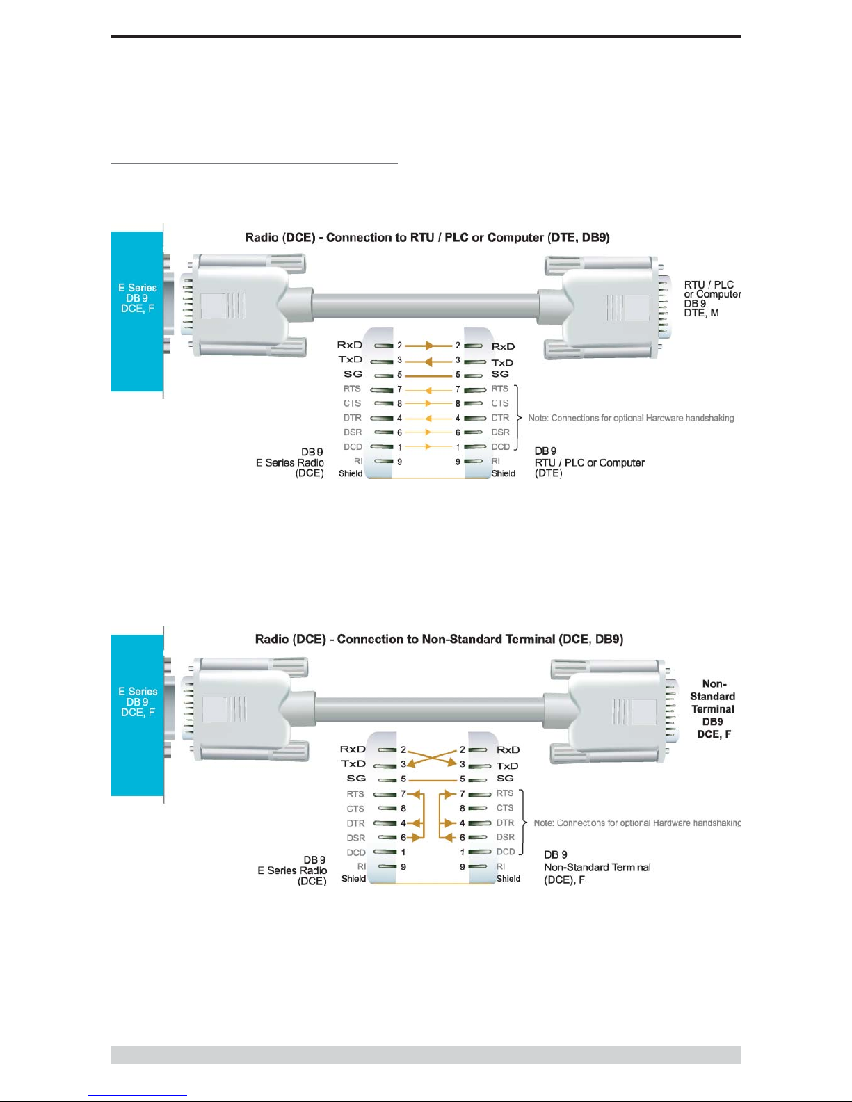
Hardware Handshaking
Hardware handshake lines are also employed to provide flow
control, however (in the telemetry industry) many devices do not
always support all (or any) flow control lines.
For this reason, the E Series modems can be configured for full
hardware flow control, or no flow control at all (simple 3 wire
interface).
Note: that when connecting devices together with differing
handshake implementations, it is sometimes necessary to “loop”
handshake pins in order to fool the devices handshaking
requirements.
In telemetry applications (particularly where port speeds can be set
to the same rate as the radio systems over-air rate) then flow
control, and therefore handshaking, is usually NOT required. It
follows that any devices that CAN be configured for “no flow
control” should be used in this mode to simplify cabling
requirements.
Handshaking lines can generally be looped as follows:
DTE (terminal) – loop RTS to CTS, and DTR to DSR and DCE.
DCE (modem) - loop DSR to DTR and RTS (note-not required for
E Series modem when set for no handshaking).
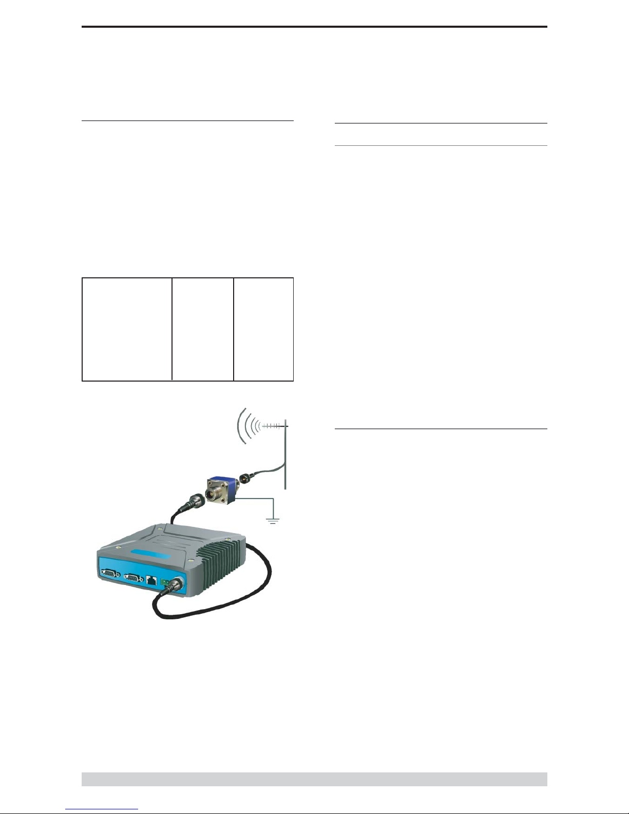
RF Feeders and Protection
The antenna is connected to the radio modem by way of an RF
feeder. In choosing the feeder type, one must compromise
between the loss caused by the feeder, and the cost, flexibility, and
bulk of lower loss feeders. To do this, it is often prudent to perform
path analysis first, in order to determine how much “spare” signal
can be allowed to be lost in the feeder. The feeder is also a critical
part of the lightning protection system.
All elevated antennas may be exposed to induced or direct
lightning strikes, and correct grounding of the feeder and mast are
an essential part of this process. Gas discharge lightning arresters
should also be fitted to any site that stands elevated or alone,
particularly in rural areas.
Page 16
E Series Data Radio – User Manual
© Copyright 2002 Trio DataCom Pty. Ltd.
Part D System Planning and Design
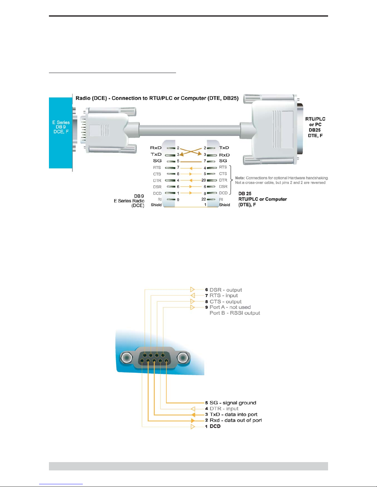
Cable Wiring Diagrams
Page 17
E Series Data Radio – User Manual
© Copyright 2002 Trio DataCom Pty. Ltd.
Part D System Planning and Design
RS232 Connector Pin outs (DCE)
Port A and B, Female DB9
Cable Wiring Diagrams
Page 18
E Series Data Radio – User Manual
© Copyright 2002 Trio DataCom Pty. Ltd.
Part D System Planning and Design
Power Supply and Environmental
Considerations
General
When mounting the equipment, consideration should be given to
the environmental aspects of the site. The cabinet should be
positioned so that it is shaded from hot afternoon sun, or icy cold
wind. Whilst the radios are designed for harsh temperature
extremes, they will give a longer service life if operated in a more
stable temperature environment. In an industrial environment, the
radio modems should be isolated from excessive vibration, which
can destroy electronic components, joints, and crystals.
The cabinet should provide full protection from moisture, dust,
corrosive atmospheres, and other aspects such as ants and small
vermin (who’s residues can be corrosive or conductive). The radio
modem will radiate heat from the in-built heatsink, and the higher
the transmitter duty cycle, the more heat will be radiated from the
heatsink. Ensure there is sufficient ventilation in the form of
passive or forced air circulation to ensure that the radio is able to
maintain quoted temperature limits.
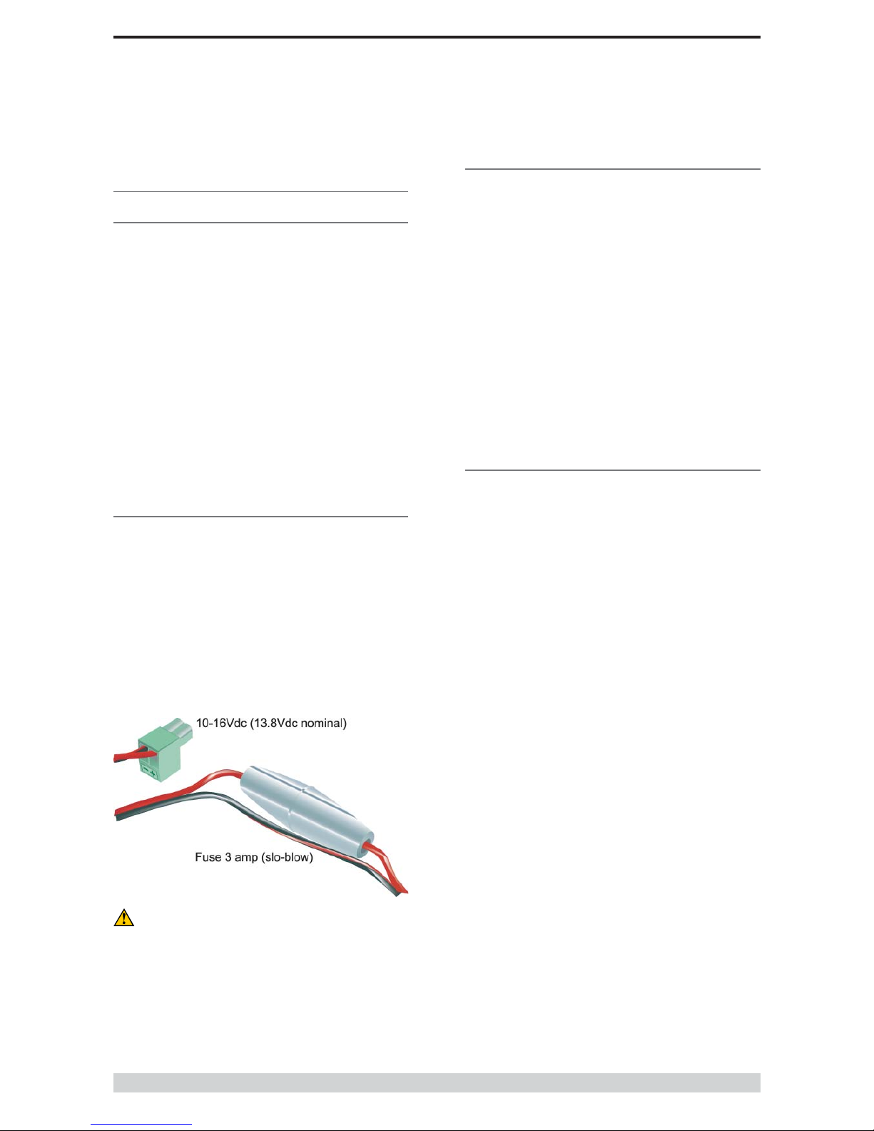
Power Supply
The power supply should provide a clean, filtered DC source. The
radio modem is designed and calibrated to operate from a
13.8VDC regulated supply, but will operate from 10-15 volts
(filtered)DC.
The power supply must be able to supply sufficient current to
provide clean filtered DC under the full current conditions of the
radio modem (ie when transmitting full RF power). The current
requirement is typically 120mA (230mA for EB450) in receive
mode, and will vary in transmit mode according to RF output power
level (typically 0.5-1.5 amps, 1.3-2.5 amps for EB450).
Solar Applications
In solar or battery-backed installations, a battery management unit
should be fitted to cut off power to the radio when battery levels fall
below the minimum voltage specification of the radio. In solar
applications, a solar regulation unit MUST ALSO be fitted to ensure
that the radio (and battery) is protected from excessive voltage
under full sun conditions.
When calculating solar and battery capacity requirements, the
constant current consumption will be approximately equal to the
transmit current multiplied by the duty cycle of the transmitter, plus
the receive current multiplied by the (remaining) duty cycle of the
receiver.
The Tx/Rx duty cycle will be entirely dependent on the amount of
data being transmitted by the radio modem, unless the device has
been configured for continuous transmit, in which case the
constant current consumption will be equal to the transmit current
only (at 100% duty cycle).
Site Earthing
The radio must not be allowed to provide a ground path from
chassis to (DB9) signal ground or (-) battery ground. Ensure that
the chassis mounting plate, power supply (-) earth, RTU terminal
device, and lightning arrester (if fitted), are all securely earthed to a
common ground point to which an earth stake is attached. Please
pay particular attention to 24VDC PLC systems using DC-DC
converters to supply 13.8Vdc.
Caution: There is NO internal replaceable fuse, and
therefore the radio modem MUST be externally fused with
the fuse holder provided (ER450: 3 amp slo-blow fuse,
EB450: 5 amp fast-blow fuse).

Page 19
E Series Data Radio – User Manual
© Copyright 2002 Trio DataCom Pty. Ltd.
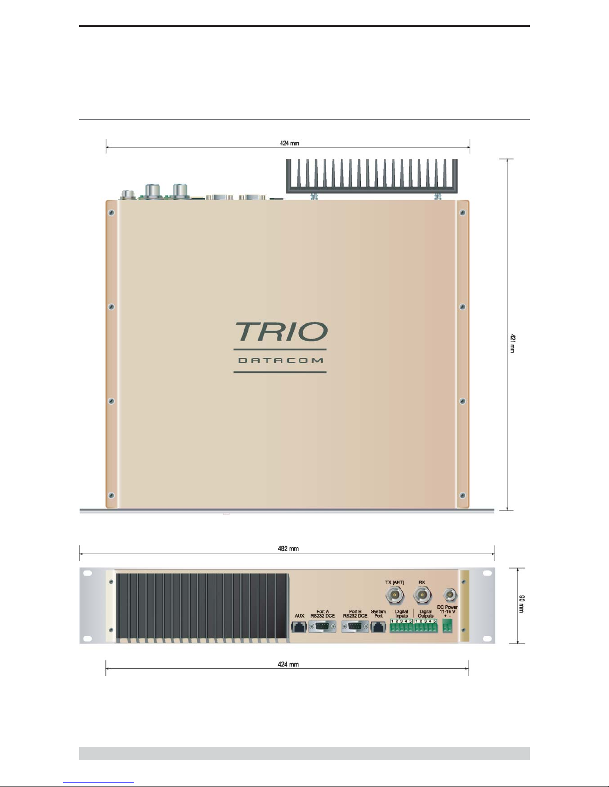
Physical Dimensions of the Remote Data Radio - ER450
Page 20
E Series Data Radio – User Manual
© Copyright 2002 Trio DataCom Pty. Ltd.
Physical Dimensions of the Base Station - EB450
Other manuals for ER450
2
This manual suits for next models
2
Table of contents
Other Trio Radio manuals


