Meters UK EM606 M-Bus User manual

EM606 M-Bus
METERSUK
L
T
D
User Manual
KEY FEATURES
The EM606 is three phase kWh M-bus meter with a LCD display in a
4 module (60mm) casing, ensuring a high accuracy class (Class1)
Excellent long term stability which is designed for DIN, IEN and
EN standards and 1 year warranty.
MID B approval which ensures the meter is produced to European
and International standards and the meter is legally suited for both
business and invoicing purposes.
For connection rate of up to 950A.
s a l e s @ m e t e r s . c o . u k 0 1 5 2 4 5 5 5 9 2 9
Three Phase 4 module energy meter
METER SPECIFICATION
-25°C to +55°C
-30°C to +70°C
Performance Criteria
Operating Humidity ≤ 75%
Storage Humidity ≤ 95%
Operating Temperature
Storage Temperature
International Standard
Active Energy Meters Class 1/B IEC62053-23| EN50470-1/3
Reactive Energy Meters Class 2 IEC62053-23
Voltage, LN & LL (Phase 1,2,3) ± 0.5%
Amps (Phase 1,2,3) ± 0.5%
PF (Phase 1,2,3 & ∑) ± 0.2%
Active Power (Phase 1,2,3 & ∑) ± 0.5%
Reactive Power (Phase 1,2,3 & ∑) ± 0.5%
Apparent Power (Phase 1,2,3 & ∑) ± 0.5%
Frequency ± 0.2%
Active Energy ± 1%
Reactive Energy ± 1%
Accuracy Class 1/B
Protection against penetration of dust and water IP51
Insulating encased meter of protective class II
The mecha nica l a nd el ectroma gnetic environmenta l cla s s es B

EM606
User Manual
Specifications
Nominal Voltage (Un)
230/400V AC (3~)
Operational Voltage
161/279 - 300/520V AC (3~)
AC voltage withstand 4KV for 1 minute
Impulse voltage withstand
6KV - 1.2 µ S waveform
Basic Current (Ib) 1.5/10A
Max. (Imax) 6/100A
Starting current (Ist)
0.4% of Ib
Imin | Itr
5%Ib | 10% Ib
Over current withstand
30Imax for 0.01s
Operational frequency range
50Hz ±10% | 60Hz ±10%
Internal power consumption
≤2W /10VA per phase
Power consumption on current circuit ≤ 4VA
Test output flash rate (PULSE LED)
400, 800, 1600 or 3200imp/kWh
Test pulse output rate (pins 8 & 9)
400, 800, 1600 or 3200imp/kWh
CT Changing Ratio
27 ratios to choose
Power supply indicator (Phase A, B & C) Meter is connected. A/B/C voltage power on
Consumption indicator (Pulse & SO LED) Flashing
Communication indicator Communication symbol flashes
Data Communication port Mbus
Data Save 20 years + when power off
Dimensions
Width x Height x Depth (mm) 17.5 x 112 x 60
Weight 0.4kg (net)
M-Bus communication specifications:
Bus type
baud rate
Range
Downlink signal
Uplink signal
Cable
Protocol
Max. Number of meters
*Note that the maximum number of meters is dependent on the converter, baud rate (the higher the baud rate the smaller
the number of meters which can be used) and the circumstances under which the meters are installed.
M-bus
2400 (default)、4800, 9600
≤1000m 64PCS*
Master to slave,Voltage modulation
Slave to master,Current modulation
JYSTY (n×2×0.8)
l EN13757-3
64*
0.05Ib≤I<0.1Ib 1.0 ±1.5 1.0 ±2.5
0.1Ib≤I<Imax 1.0 ±1.0 0.5L or 0.8C ±2.0
0.1Ib≤I<0.2Ib 0.5L or 0.8C ±1.5 1.0 ±2.5
0.2Ib≤I<Imax 0.5L or 0.8C ±1.0 0.5L or 0.8C ±2.0
Current value
Power fac tor COSΦ
Error%
Power fac tor SINФ
Error %
Ac tive Class 1.0
Reac tive 2.0
BASIC ERRORS (with balanced loads)

EM606
User Manual
Register material: PC inflammable retarding
Case/Terminal Block/Cover: ABS inflammable retarding
DIMENSIONS AND INSTALLATION
110
110
90
44.86
70 70
4.5
Installation
Energy Use indicator
We recommend that the connecting wire which is used to connect the meter to the outside circuit should be sized according
to local codes and regulations for the capacity of the circuit breaker or over current device used in the circuit.
An external switch or a circuit-breaker should be installed on the inlet wire, which will be used as a disconnection device for
the meter. And there it is recommended that the switch or circuit-breaker is near the meter so that it is more convenience for
the operator. The switch or circuit-breaker should comply with the specifications of the building electrical design and all local
regulations
An external fuse or thermal cut-off which will be used as a over-current protection device for the meter must be installed on the
supply side wire, and it is recommended that the over-current protection device is near the meter so that it is more convenience
for the operator. The over-current protection device should comply with the specifications of the buildings electrical design and
all local regulations.
This meter can be installed indoor directly, or in a meter box which is waterproof outdoor, subject to local codes and regulations.
To prevent tampering, secure the meter with a padlock or a similar device.
The meter has to be installed against a wall which is fire resistant.
The meter has to be installed in a good ventilated and dry place.
The meter has to be installed in a protection box when placed in dangerous or dusty environment.
The meter can be installed and used after being tested and sealed with a letter press printing.
The meter can be installed on a 35mm DIN rail.
The meter should be installed in an available height so that it is easy to read.
When the meter is installed in an area with frequent surges due to e.q. thunderstorms, welding machines, inverters etc,
protect the meter with Surge Protection Devices.
After finishing installation, the meter must be sealed to prevent tampering.
Connection of the wires should be done as below:-
30
32
34
L1
L3
31
33
35
L2
N
Reactive pulse output contact active (-) “-”
Active pulse output contact “-”
BUS2 (Mbus)
L1 phase wire
L3 phase wire
Reactive pulse output contact active (+) “+”
Active pulse output contact “+”
BUS1 (Mbus)
L2 phase wire
Neutral wire
EM606
User ManualUser Manual
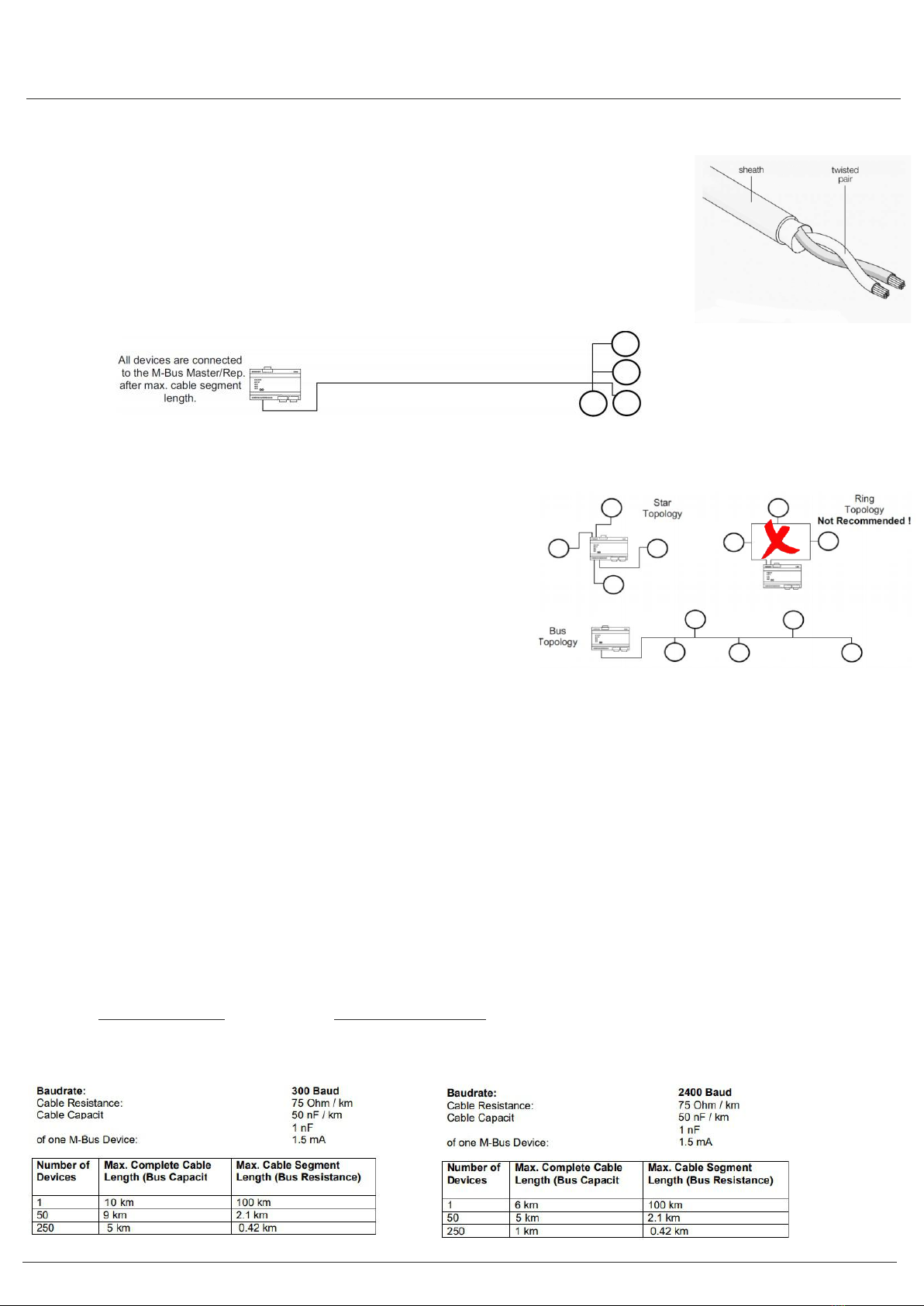
5A. TYPE OF CABLE TO USE
The M-Bus uses two wire cables which are going from the M-Bus Master / Repeater to each
M-Bus device (bus structure).
The M-Bus is polarity independent and needs no line termination resistors at the end of the cables.
Any cable type may be used as long as the cable is suitable for 36 V / 500 mA.
Shielding is not necessary and not recommended since the capacitance of the cable should be minimized.
In most cases a standard telephone cable is used which is a twisted pair wire with a diameter of 0.5 mm
each (2 x 0.8 mm is also suitable). This type of cable should be used for the main wiring.
For the wiring to the meters from the main wiring (last 1 .. 5m to the meter) a cable with smaller diameter may be used.
5B. M-BUS BASICS
The topology of the M-Bus network is (almost) arbitrary. Only the ring
topology as shown should be avoided. In general the length of the
cables should be minimized and a mixture between star and bus
topology should be used.
The limiting parameters in M-Bus networks are mainly the cable
resistance and the cable capacitance plus the capacitance of the devices
(= bus capacitance). Cable resistance will cause, a bus voltage drop.
The maximum drop may not be more than 11 V .. 12 V, as the
minimum bus voltage at any device must not be lower than
24 V (36 V – 24 V = 12 V).
The cable resistance, therefore, limits the maximum possible cable length from the MBus Master / Repeater to the device with
the largest distance away from it (largest cable segment). The cable segment length is the distance from the M-Bus Master to
the M-Bus device furthest away.
NOTE: The given maximum cable segment length takes into account only the bus resistance and not the bus capacitance.
Therefore, some of the cable lengths in the table may not be possible in reality.
The cable capacitance plus the capacitance of the M-Bus devices (= bus capacitance) is responsible for sloppy signal edges.
Therefore, the bus capacitance limits the maximum data transfer rate of the M-Bus. The M-Bus Master is able to drive approx.
0,8 µF at a baud rate of 300 baud.
5C. BAUD RATE & BIT RATES
Bit rate is a measurement of the number of data bits (that's 0's and 1's) transmitted in one second. A figure of 2400 bits per sec
means 2400 zeros or ones can be transmitted in one second, hence the abbreviation 'bps'. Baud rate by definition means the
number of times a signal in a communications channel changes state.
Common Settings for M-bus - 300 or 2400. Parity (Error Checking) is EVEN or NONE.
ALL items MUST have the same settings otherwise they CANNOT communicate.
ance:
ance:
Current capacitance of one M-Bus device:
Current capacitance of one M-Bus device:
ance)
ance)

User Manual
INSTALLATION DIAGRAM
EM606
LINE 1
LINE 2
LINE 3
NEUTRAL
NEUTRAL IN
28 29
27 26
30 31
25 24
32 33
23 22
34 35
21 20
L1
L1
L2
L2
L3
L3
N
N
BUS2
BUS1
SO
+
-
K
SUPPLY
L
LOAD
METER
S2 S1
Fused
3x230/400V 0,015-1,5(6)A
EN50470-3 50-60Hz 3K6
RI=3200
imp/kWh
!B
SEL
PRG M20 0122
EM-606
M-BUS
S m a r t L i n k
123456.0.0
888888.8.8
L1 230
88 88.8.8
:
User Manual
EM606
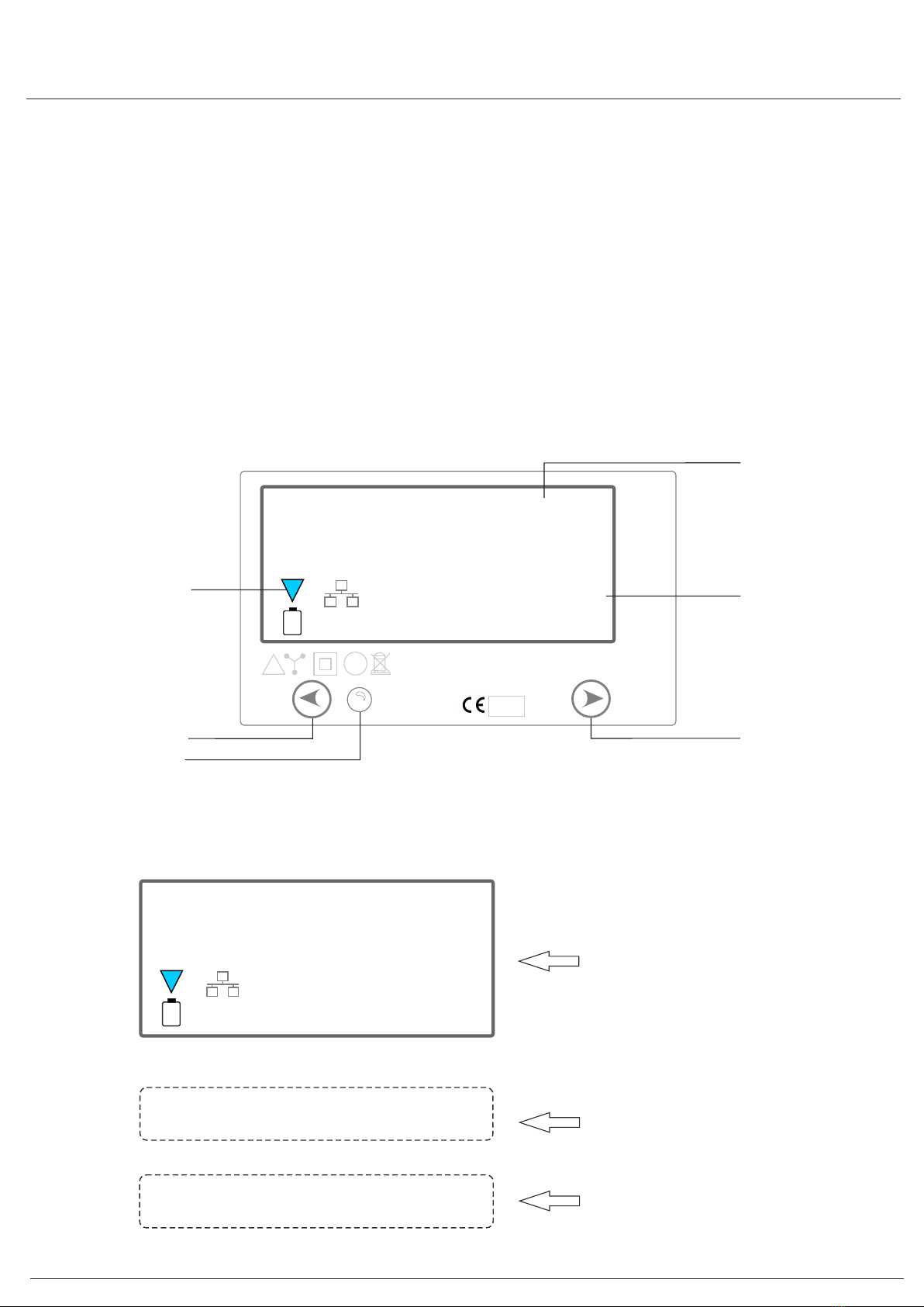
OPERATING
Energy Usage
The LCD will display L1,L2,L3,the voltage and current bearing
The other indicator is for pulse output. When electricity is used; the LED will flash red. The more quickly LED flashes, the more
energy is being used.
Reading the Meter
LCD numerical display : 8 (6 + 2). 6 digits for the sub-display items.
LCD Display
MP
EXP
Kvarh
kWh
MP
EXP
Kvarh
kWh
Hz
Kvar
KWA
MD
Hz
Kvar
KWA
Accumulated Energy
(Auto-scroll only)
V / I / P / PF / Hz /Comms
(Auto or Manual scroll)
Scroll / Select Button
Pulse Output Indicator
Phase Failure Indicator
(Negative or OV)
Config / Change Button
C 400
7fd6
The constant
The software version
Full Screen
will last for 3 sec.

User Manual
EM606
0000000.8
000000.00
0000000.8
l3 229
l1 230
l3 229
IMP
EXP
Kvarh
kWh
IMP
EXP
Kvarh
kWh
IMP
EXP
Kvarh
kWh
0000001.3
l2 230
IMP
EXP
Kvarh
kWh
Hz
Kvar
VK A
000000.00
l1 0.4
IMP
EXP
Kvarh
kWh
Hz
Kvar
KWA
000000.00
l2 230
IMP
EXP
Kvarh
kWh
Hz
Kvar
K AV
Hz
Kvar
K AW
Hz
Kvar
K AV
Hz
Kvar
KWA
Forward
Total Active kWh
Total Reactive kWh
Export
Total Active kWh
L1 Voltage
L2 Voltage L3 Voltage
000000.40
0000000.8
l2 59.6
p 6.89
000000.40
pf 1.00
MP
EXP
Kvarh
kWh
MP
EXP
Kvarh
kWh
MP
EXP
Kvarh
kWh
000000.00
l1 59.6
MP
EXP
Kvarh
kWh
Hz
Kvar
KWA
000000.40
l3 59.6
MP
EXP
Kvarh
kWh
Hz
Kvar
KWA
Hz
Kvar
KWA
Hz
Kvar
KWA
L1 Current L2 Current
L3 Current Active Power
Power Factor
000000.40
f 50
MP
EXP
Kvarh
kWh
Hz
Kvar
KWA
Frequency
000000.40
bd 2400
IMP
EXP
Kvarh
kWh
000000.40
9 0.00
IMP
EXP
Kvarh
kWh
Hz
Kvar
KVA
Hz
Kvar
KWA
Reactive Power Baud Rate

User Manual
EM606
000000.40
000000.40
000000.40
id 01
sl 0000
sH 0000
IMP
EXP
Kvarh
kWh
IMP
EXP
Kvarh
kWh
IMP
EXP
Kvarh
kWh
Hz
Kvar
KWA
Hz
Kvar
KVA
Hz
Kvar
KVA
ID Address Serial number
(high digit)
Serial number
(low digit)
Communication
Display (flashing)
I
I
I
I
I
I
I
I
I
I
I
I
I
I
I
I
I
I
I
I
I
I
l
l
l
l
l
l
l
l
l
l
l
l
l
l
l
l
888888.8.8
L1 59.6
MP
EXP
Kvarh
kWh
Hz
Kvar
KWA
will flash to indicate that the value of
current is negative
888888.40
L3 0
MP
EXP
Kvarh
kWh
Hz
Kvar
K AV
will flash to indicate that the value of
display is zero
l
l
l
l
l
l
l
l
l
l
l
l
l
l
l
l
It is used as recording consumption and can’t be reset to zero. The reading accuracy is 1/100 kWh.
Button operation:
Right button is selection , left button is program .
Button selection : one short press, lighting the backlight, then press one time show one parameter,
the order is as following: voltage of one phase, current of one phase, active power, reactive power, frequency, baud rate,
ID address, serial number, in total 13 parameters, after one minute the backlight will close automatically.
Press left button more than 3 seconds enter in code confirmation process, use right button choose the
code number then use left button change the digit place, when finish code entering use left button press more than 3 seconds
for confirmation then display show ID 01, use left button to change the display item, use right button to change the information.
The items can be settled is : 1: ID; 2: baud rate, 3: number of display item (The number of Phase voltage, phase current,
active power, reactive power, frequency, communication baud rate, ID address, serial number), 4 CT ratio setting for CT
connection meter.
Pulse output
The EM606 Series DIN rail energy meter is equipped with a pulse output which is fully separated from the inside circuit.
That generates pulses in proportion to the measured energy for accuracy testing.
User Manual
EM606
000000.0.0
L1 230
MP
EXP
Kvarh
kWh
Hz
Kvar
K AV
Display once kWh screen shown
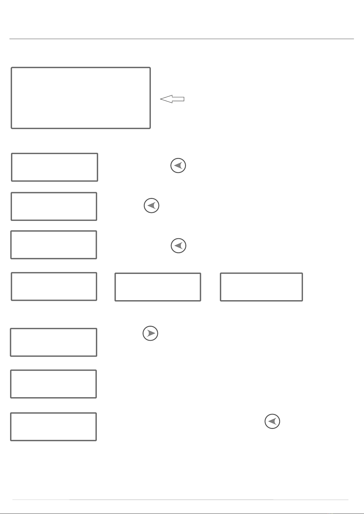
CT RATIO SETTING INSTRUCTIONS
P5 0000
Press and hold the PRG button for 5 seconds.
P5 0001
Press the SEL button once and select “1”. The password selected is 0001
Id 01
Press and hold the PRG button for 5 seconds. The ID button will display.
bd 2400 Sn oe CR 1
Cr 100
Press the SEL button for to set the CT ratios. They can be set at 27 different ratios.
(1,2,5,8,10,12,15, 16,20,24,30,40,50,60,70,80,90,100, 110,120,130,140,150,160,170,180,190)
S--500
ie. If you select CT ratio 100, it will display Ct100.
To check it, turn the meter off and then on again. The 4th screen will display 5--500.
yes
Once you have set the CT ratios, press and hold the PRG button for 5 seconds,
YES will display showing that the settings are now programmed.
Notes
1. Press and hold the SEL button to switch on the screen. The screen will automatically turned off after 1 minute.
The SEL button, when pressed, will display 14 screens: Phase Voltage (L1, L2, L3), Phase Current (L1, L2, L3), Active Power,
Power Factor, Reactive Power, Frequency, Baud Rate, ID, Serial number (high position, low position).

User Manual
EM606
2. Press on hold the PRG button for 5 seconds, the sub display to display P50000; (Press the left PRG button to select the
digit position (digit is flashing), right button to select the corresponding digit. Modify the flashing password number--long press
left PRG button 5 seconds to confirm (factory password 0001).
3. Long Press left PRG button 5 seconds to enter the settable item: 1-ID; 2-baud rate; 3-set the number of cycle display screens
(14 sub-screens); 4- CT ratio, there are 27 ratio settings (CT type default 5:5).
4. Left PRG button to select the corresponding setting item, press the right SEL button to select the sub-item under the setting
item. After all the settings are completed, long press the left PRG button 5 seconds to save the setting. The screen displays
“YES” to indicate that the setting is successful.
If the setting is in the state of automatic setting, the system defaults to the setting in this state.
QUICK PROGRAMMING GUIDE
Connect mains power to the meter –
Live to the small terminal labelled 27 at the lower left
Neutral to the large terminal labelled N at the upper right
Switch the power on and wait until the meter completes startup (after it shows the CT ratio)
Press and hold the “PRG” button for 3 seconds – the display will show “PS 0000”
Press the “SEL” button once so that the display changes to “PS 0001”
Press and hold the “PRG” button for 3 seconds to enter the password
If the password was correct (default = 0001) the meter is now in programming mode
The first item is “Id” which is the Mbus address and is in 2 digit hexadecimal format
Use “SEL” to increment the address and “PRG” to move to the next item
The next item is “bd” which is the Mbus baud rate. There are 5 possible values –
0600, 1200, 2400, 4800 & 9600
Use “SEL” to increment the baud rate and “PRG” to move to the next item
The next item is “Sn” which is the number of parameters to show on the scrolling display and is in 2 digit
hexadecimal format. The default value is “0E” but due to a software bug the maximum value that can be set when
it is altered is “0d”.
Use “SEL” to increment the value and “PRG” to move to the next item
The final item is “Cr” which is the CT ratio. This value is multiplied by 5 to give the CT current rating.
There are 27 possible values –
1, 2, 5, 8, 10, 12, 15, 16, 20, 24, 30, 40, 50, 60, 70, 80, 90,
100, 110, 120, 130, 140, 150, 160, 170, 180 & 190
Use “SEL” to increment the value
Press and hold the “PRG” button for 3 seconds to save the settings – the display will show “YES” to confirm that they
have been saved.

User Manual
EM606
s a l e s @ m e t e r s . c o . u k | W h i t e L u n d I n d u s t r i a l E s t a t e L a n c a s t e r L A 3 3 B T | 0 1 5 2 4 5 5 5 9 2 9
TROUBLE SHOOTING
The power supply
indicators are off.
(L1, L2 & L3 LED)
The register
doesn’t count.
No pulse outputs.
The pulse output rate is
incorrect Please contact technical support.
Are the fuses or/and surge protection
defect?
Make sure the wires are connected properly
and tighten the screws if possible.
Check if there is 230V AC voltage between N
and one of the L connections with a voltage
meter.
Check if there is 400V AC volt between N and
one of the L connections with a voltage meter.
If the checks above don’t solve the problem,
please contact technical support.
The meter is not connected to a
power source
L1, L2, L3 and N are not connected
correctly
There is no 230V AC between the N
and one of the L connections when
power is supplied to the meter.
There is no 400V AC between the L
connections when power is
supplied to the meter.
There is almost no load connected to
the meter.
The pulse output is not supplied with
DC power.
The pulse output is not connected
correctly.
Still no response.
Check if the (P-: red or P+: green) consumption
led is flashing. 40 flashes of the LED at 400
pulses per kWh equals 0.1kWh.
Check the external voltage source (Ui) is 5-27V
DC with a voltage meter
Check if the connection is correct: the 5-27V DC
should be connected to the collector connection
(pin 28+ or pin 30+) and the signal wire (S) to
the emitter connection (pin 29- or 31-)
Please contact technical support.
The consumption LED
is not flashing.
The pulse cable is not connected.
The load on the line is very low.
Connect the pulse cable.
Check the Ohm meter readings
No data received by the
M-Bus communication
port.
The ID is not correct.
The communication distance
is too long.
Too many meters connected.
The M-Bus terminals are not
connected correctly.
Check the Meter ID by looking for the A in the
display. The number in front of the A, for
example 15A gives the actual address the
meter uses. The default for this meter is 0A.
Make the distance between the meter and the
reading device shorter. Make sure it is no more
than ≤1000m
The number of M bus devices connected to the
meter should not exceed 64.
Make sure that the M-bus wires are connected
to terminals 34and 35. If the checks above
don’t solve the problem, please contact
technical support for a meter replacement.
Table of contents
Other Meters UK Measuring Instrument manuals

Meters UK
Meters UK SmartLink45 4000123456789 User manual

Meters UK
Meters UK SmartLink 45 User manual

Meters UK
Meters UK SmartLink 45 User manual

Meters UK
Meters UK SmartLink45 User manual

Meters UK
Meters UK 3MB100 User manual

Meters UK
Meters UK MOD3CT User manual

Meters UK
Meters UK SmartLink45 4000123456789 User manual
Popular Measuring Instrument manuals by other brands


Hach Ultra
Hach Ultra ORBISPHERE 29981 Operator's quick guide

Hantek
Hantek HT8000 Series instruction manual

Thyracont
Thyracont VD8 Series operating instructions

LOVATO ELECTRIC
LOVATO ELECTRIC DMECD installation manual

Hitachi
Hitachi EUP-L54MA instruction manual

Agilent Technologies
Agilent Technologies ESA Series Getting started guide


