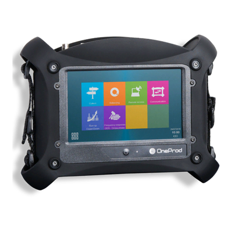
OneProd HAWK User manual

1
HAWK
USER MANUAL

2
Brand of ACOEM

3
Brand of ACOEM
Document reference: DOC3122 –OCTOBER 2014 A
Name: HAWK USER MANUAL
www.acoemgroup.com
support@acoemgroup.com
Copyright © 2014, 01dB-Metravib SAS
This document is the property of 01dB-Metravib SAS. Any dissemination, copying or publicising of this document, in whole or in
part, is prohibited without the owner’s written authorisation.
HAWK
USER MANUAL

4
Brand of ACOEM
TABLE OF CONTENT
General presentation...................................................................................................... 6CHAPTER 1.
1.1 Introduction............................................................................................................................ 6
1.2 Safety instructions ................................................................................................................. 6
1.3 First power-up........................................................................................................................ 6
1.4 User interface ........................................................................................................................ 7
1.5 Connections........................................................................................................................... 7
1.6 Built-in sensors...................................................................................................................... 8
1.7 Wireless Sensor .................................................................................................................... 9
1.8 Data exchange with PC....................................................................................................... 10
1.9 Status indications ................................................................................................................ 12
1.10 Shortcuts panel.................................................................................................................... 13
1.11 Battery management ........................................................................................................... 17
1.12 Remote Display & Control function ..................................................................................... 19
General settings........................................................................................................... 20CHAPTER 2.
2.1 Collect.................................................................................................................................. 20
2.2 Measurement....................................................................................................................... 20
2.3 Wireless sensor................................................................................................................... 21
2.4 Tachometer.......................................................................................................................... 22
2.5 Spectrum display................................................................................................................. 22
2.6 Camera................................................................................................................................ 23
2.7 Touchscreen........................................................................................................................ 23
2.8 About ................................................................................................................................... 23
2.9 Date –language .................................................................................................................. 24
2.10 Network................................................................................................................................ 24
2.11 Data management............................................................................................................... 25
2.12 Update firmware .................................................................................................................. 25
2.13 Auto test............................................................................................................................... 25
2.14 Calibration............................................................................................................................ 26
2.15 Battery management ........................................................................................................... 26
2.16 Mix of wired and wireless sensors....................................................................................... 26
Supervisor module ....................................................................................................... 28CHAPTER 3.
3.1 Introduction.......................................................................................................................... 28
3.2 Cloud server architecture .................................................................................................... 28
3.3 First connection to the NEST software................................................................................ 29
3.4 Create a machine in NEST software................................................................................... 29
3.5 Load a machine on HAWK.................................................................................................. 35
3.6 Make measurements with HAWK Supervisor ..................................................................... 36
3.7 Display measurements........................................................................................................ 42
3.8 Run automatic diagnosis..................................................................................................... 44
3.9 Add comments to the diagnosis .......................................................................................... 45
3.10 Transfer measurements to NEST Software ........................................................................ 45
3.11 Print a report from NEST Supervision module .................................................................... 46
3.12 Ask for remote assistance from NEST Supervision module ............................................... 48
3.13 Copy / Paste machines on HAWK....................................................................................... 49
Balancing module......................................................................................................... 50CHAPTER 4.
4.1 Balancing module guideline................................................................................................. 51
4.2 Folder list............................................................................................................................. 52
4.3 Balancing List ...................................................................................................................... 52
4.4 Installing the equipment....................................................................................................... 53
4.5 Setup ................................................................................................................................... 54
4.6 Run-out measurement......................................................................................................... 57
4.7 Free run............................................................................................................................... 58

5
Brand of ACOEM
4.8 Trial run................................................................................................................................ 59
4.9 Balancing result................................................................................................................... 61
4.10 Trim steps............................................................................................................................ 62
4.11 Steps browser...................................................................................................................... 62
4.12 One run balancing ............................................................................................................... 62
4.13 Report.................................................................................................................................. 63
Maintenance................................................................................................................. 64CHAPTER 5.
5.1 RESET................................................................................................................................. 64
5.2 Cleaning............................................................................................................................... 64
5.3 Calibration............................................................................................................................ 64
5.4 Backup of instrument memory............................................................................................. 64
5.5 Instrument firmware update................................................................................................. 64
5.6 WLS sensor firmware update.............................................................................................. 64
5.7 Screen frame protection...................................................................................................... 65
Appendix ...................................................................................................................... 66CHAPTER 6.
6.1 Appendix 1: Data storage organization ............................................................................... 66

6
Brand of ACOEM
GENERAL PRESENTATIONCHAPTER 1.
1.1 INTRODUCTION
We want to congratulate you on your choice and hope that you will be fully satisfied with it. For this reason, we
recommend that you read carefully the present user guide and more specifically the safety instructions.
Designed to meet industrial requirements for enhancing productivity, HAWK is a portable multichannel instrument
coming along with a large touchscreen, a 3-axis wireless sensor and numerous accessories. This innovative all-in-
one solution makes vibration analysis available to all users.
HAWK is available in 2 versions. The HAWK (red rubber) is for safe area, and the HAWK-EX (black rubber) for
ATEX Zone II area. All functionalities described in this manual are applicable to both versions.
1.2 SAFETY INSTRUCTIONS
The safety instructions delivered with the instrument (printed and on the CDROM) should be carefully
followed and the instrument should always be used within the limits specified here.
1.3 FIRST POWER-UP
The instrument turns on automatically a few seconds after being connected to the mains through the power supply
module. If the battery level is too low, the charge starts and goes on as long as the instrument is connected to its
power supply.
When using a new battery, leave the battery in charge for about 10 hours in order to achieve full charge. Do not
use the instrument prior to 2-3 hours of charge. Usual charging time is about 6 hours when instrument is switched
off.
On-Off:
oPower on: press the On-Off key
oPower off: press the On-Off key, then message “Shutdown”
Battery charge:
oConnect the instrument to the charger
oConnect the charger on the main. The instrument is automatically powered on. During the charge you
can continue to use it. For a faster charge it is recommended to switch-off the instrument. A full charge
requires about 6 hours.
It is recommended to disconnect the charger from the main when you are not using it.

7
Brand of ACOEM
1.4 USER INTERFACE
HAWK starts on its “Home screen”. It is a touch screen and a simple pressure on it gives access to the application
modules installed on the instrument and to 2 side panels:
For more details:
Supervisor module: see CHAPTER 3
Balancing module: see CHAPTER 4
Status panel: see § 1.9
Shortcuts panel: see § 1.10
The 2 side panels are accessible from any screen.
1.5 CONNECTIONS
1.5.1 Connectors A to D on the top of the instrument
Those connectors can be used in industrial environment. They are IP65.
Connector A: channels 1 and 3. Use this connector when the instrument is set in single-channel mode.
Connector B: channels 2, 3 and 4. Use this connector with wired triaxial sensor when the instrument is set
in multi-channel mode.
Note: for 2-channel measurement, use connectors A and B. For 4-channel measurement, you also need Y
adaptors.
Connector C: Tachometer input, Stroboscope output, Power supply input. It is marked in yellow as well as
all cables used on this connector
Connector D: Ethernet, Microphone input, Audio output.
Warning:
Do not connect channels 1, 2, 3, 4 and tachometer input on a not buffered output or in parallel
to other instrument as their impedance is not maintained when changing configuration or when
the instrument is switched off.
Respect the maximum input voltage to the A/B/C/D connectors: maximum input voltage ± 24 V
DC, ± 24 volts peak AC.
Access to
application
modules
Access to
status side
panel
Access to
shortcuts
side panel
A
B
C
D
Antenna for WLS
sensor and Wi-Fi

8
Brand of ACOEM
1.5.2 Connectors E to I behind the trapdoor
Those connectors are behind a trapdoor. It must remain close in industrial environment to preserve the IP65
protection. Use those connectors only in office environment.
Connector E: Power supply input
Connector F: Ethernet RJ45
Connector G: USB 2 type A host (for USB memory stick)
Connector H: USB 2 type B device (direct connection with PC)
Connector I: serial interface for maintenance purposes only
1.6 BUILT-IN SENSORS
The back of the instrument gives access to the built-in sensors.
For the stroboscope and the pyrometer, please see the safety instructions delivered with the instrument
(printed and on the CDROM)
High-power LED for
stroboscope and
camera flash
Laser beam source
for pyrometer sighting
Pyrometer window
Camera window
E
F
G
H

9
Brand of ACOEM
1.7 WIRELESS SENSOR
HAWK can be used with a wireless triaxial accelerometer (WLS Sensor). This chapter described
how to use HAWK with this sensor.
1.7.1 WLS sensor battery
Use the USB cable and charger supplied with the sensor. The connector is protected by the
rubber cap on the top of the sensor. It can also be charged from any USB interface with power
supply (! measurement is not possible if the WLS is connected to a USB PC port). Charging time
is 8 hours with the standard 500 mA charge current.
Note: WLS sensor battery replacement must be done by qualified personnel only.
1.7.2 WLS sensor first connection
Switch on WLS: press on/off for 2s, until the red LED is on, and wait until the red LED is off and the blue
LED is continuously on. See details below concerning LED indication.
On HAWK from the home screen proceed as follows:
oCheck first if Wi-Fi is enabled in:
Shortcuts > Setting > > Wi-Fi = enabled
oSet HAWK to work with a WLS sensor:
Shortcuts > Setting > > Accelerometer link = Wireless
oShortcuts > Setting > Wireless sensor:
Input WLS serial number (e.g., 10015)
Save the settings
Wait for about 30 s until the blue LED is flashing. Then 20 s later, the connection must be
set up. It can be seen from the status panel where you can see the sensor identification
(e.g., WLS_10015). It can also be checked from Wireless sensor setting with the Test
function.
If Wi-Fi is enabled further connections are automatic after switch on of the instrument and the WLS sensor.
Note: it is not possible to connect an instrument with a WLS sensor already connected to another
instrument.
1.7.3 WLS sensor switch off
Press on/off for 6s until the red LED flashes on. The sensor is also automatically switched off if there is no
connectivity during 10 min.

10
Brand of ACOEM
1.7.4 WLS: LED indication
Red LED
Blue LED
Significance
WLS connected
to the charger
———
Charge in progress (LED brightness = 50%)
━━━━
Charge completed (LED brightness = 100%)
- - - - -
Charge error
Switch on
(press 2s on/off)
——— (< 10 s)
Off
Start in progress
——— (> 15 s)
Off
Error
———
WLS ready and not connected to the
instrument
- - - - -
WLS connected to the instrument
Switch off
(press 7 s on/off)
- - - - -
Stop in progress
Off
Off
WLS is switched off
Low battery
- - - - -
Notation:
━━━━ brightness = 100%
——— brightness = 50%
- - - - - flashing
Blank any status
1.8 DATA EXCHANGE WITH PC
HAWK can exchange data with the PC when the Communication module is run from the home screen. See
below the different settings according to the type of communication. Once the communication is established, you
can also use the NEST software to upload or download routes. The instrument is also seen as an external drive
from the PC (see § 6.1).
1.8.1 Using USB (Connector H)
No settings are required, the PC automatically detects the instrument after its connection.
1.8.2 Using USB memory (Connector G)
It is possible to use a USB memory stick connected on port G to exchange the following data:
Firmware update: see § 2.12
Load and download machines: see §3.5 and §3.10
Issue balancing reports: see § 4.13
Note: USB memory stick format must be FAT32, NTFS format is not accepted. It is always possible to reformat it to
FAT32.
1.8.3 Using Ethernet (Connector D or F)
Direct connection PC- HAWK setting:
oOn PC: Setup Network
DHCP = No
Set the IP address: Ex 192.168.1.10
Mask = 255.255.255.0
oOn HAWK:
Shortcuts > Setting > Network >
DHCP = No
Set the IP address = e.g., 192.168.1.12
Note: the first 3 numbers must be the same (192.168.1) and the last one different from that
of the PC (10 ≠12)
Mask = 255.255.255.0

11
Brand of ACOEM
Once the setting is done, to access the data use HAWK IP address, e.g., in the Explorer type
“\\192.168.1.10\Data”.
PC- HAWK connection through LAN Network:
oOn PC: Setup Network
DHCP = Yes
oOn HAWK:
Shortcuts > Setting > Network >
DHCP = Yes
Connect HAWK to the LAN, set it in communication mode and wait until it gets its IP address.
The IP address can be read in Setting > About information page.
If there is a DNS, it is also possible to access the instrument with its name. The name is
HAWK_serial_number (e.g., HAWK_10015).
Once the setting is done, to access the data use HAWK IP address, e.g., in the Explorer type
“\\HAWK_10015\Data”.
1.8.4 Using Wi-Fi
Check first if Wi-Fi is enabled in:
Shortcuts > Setting > > Wi-Fi = enabled
Direct Wi-Fi connection PC- HAWK setting without WLS sensor:
oOn HAWK:
Setting > Network > Wi-Fi part
Enabled = Yes
Adhoc = Yes
SSID = My_HAWK or other
Canal = 5
Authentication = none
DHCP = No
Set the IP address: Ex 192.168.1.16
Note: the first 3 numbers must be the same (192.168.1) and the last one different from that
of the PC (14 ≠16)
Mask = 255.255.255.0
oOn PC: Setup WIFI network
DHCP = No
Set the IP address, e.g., 192.168.1.14
Mask: 255.255.255.0
Scan Wi-Fi networks and select HAWK SSID.
Once the setting is done, to access the data use HAWK IP address, e.g., in the Explorer type
“\\192.168.1.16\Data”.
Direct Wi-Fi connection PC- HAWK-WLS setting:
oOn HAWK:
First set the connection HAWK-WLS: see § 1.7.2
Wait for sensor connection (status panel)
In Setting > About information page check HAWK WIFI IP address
(192.168.1.xxx with xxx the last 3 digits of HAWK serial number)
oOn PC: Setup Wi-Fi network
DHCP = No
Set the IP address: 192.168.1.yyy (yyy ≠ xxx)
Mask: 255.255.255.0
Scan Wi-Fi networks and select HAWK SSID (WLS_10015).

12
Brand of ACOEM
Once the setting is done, to access the data use HAWK IP address, e.g., in the Explorer type
“\\192.168.1.xxx\Data”.
Note: this type of communication can also be used if the WLS Sensor is switched off.
Wi-Fi LAN connection PC- HAWK setting without WLS sensor:
Note: WLS sensor cannot be used simultaneously with this mode.
oOn HAWK:
Setting > Network > Wi-Fi part
Enabled: Yes
Adhoc: No
Save the setting
Setting > Network > Wi-Fi part
Scan network until you detect the right SSID
Set Authentication, Encryption and Key according to selected SSID
DHCP: Yes
The IP address can be read in Setting > About information page.
If there is a DNS, it is also possible to access the instrument with its name. The name is:
HAWK_serial_number (e.g., HAWK_10015).
oOn PC: the PC must also be connected to the same Wi-Fi LAN
1.9 STATUS INDICATIONS
1.9.1 Status summary
The status is indicated at the bottom of the right hand side of the screen
General status
oDate and time
oBattery level of the instrument
During analogic measurement
oInput overload indication in percentage of time.
oSensor integrity indicator
During wireless measurement
oSensor overload indication in percentage of time.
oBattery level of the sensor
1.9.2 Status panel
If you click on the status summary, the status panel appears on the right hand side of the screen. It shows the
following information:
Wi-Fi:
oOff: Wi-Fi is disabled in Shortcuts > Setting >
oNot connected: the instrument is not connected to a WLS sensor or another Wi-Fi network
oWLS_xxxxx: the instrument is connected to a WLS sensor, xxxxx is the serial number of the sensor.
oNetwork: Wi-Fi is connected to a network.
Sensor battery: this information shows the battery level of the WLS sensor. It is not displayed if the
instrument is not connected to a WLS sensor.
System battery: this information shows the battery level of the instrument.
Next calibration date: display the recommended date for the next calibration.
The amount of available memory.

13
Brand of ACOEM
1.10 SHORTCUTS PANEL
From any screen, button opens the Shortcuts panel. It gives direct access to a group of functions. The list of
accessible functions depends of the current screen.
1.10.1 Photo
From the Collect module, measurement list screen: take an inspection picture
From Balancing module, any screen: take picture for your report (balanced machine, sensor installation, weight
mounting)
Take the picture:
: take the picture. You must not move during few seconds.
Brightness adjustment.
Flash on and off.
Stored picture management:
Add a new picture.
See previous picture.
See next picture.
Add a comment to the current picture.
Delete the current picture.

14
Brand of ACOEM
1.10.2 Text note
From Collect module, measurement list screen: input text inspection note directly from the keyboard or from a
list of predefined notes. The list of predefined notes is only available if this list is created in PC database (in
XPR menu “Libraries/Predefined notes”)
From Balancing module, any screen: balancing comment for the report
Keyboard details:
Keyboard type:
oEN: English
oFR: French
oPT: Portuguese
oCN: Chinese
Character selection bar: if one key is used for several characters (e.g., @#$, eéè, …), a long press
displays them in the bar for selection.
1.10.3 Help
From any screen, it gives explanation of each command .
Select
keyboard
type
Character
selection bar
Validate and
return to
previous screen
Cancel: return
to previous
screen with no
modification
Delete all
characters
Delete last
character

15
Brand of ACOEM
1.10.4 Vocal note
Before using a headphone, please read the safety instructions delivered with the instrument (printed and on the
CDROM)
From Collect module, measurement list screen: take a vocal inspection note.
Record: record your comment.
Make sure you set the volume to a low level before starting to listen
Play: listen to the comment
For this function, you must have the optional 3.5 mm jack adapter on connector D (ref: CPC1229000 - HAWK
ECTD-JACKF).
1.10.5 Barcode
From the Collect module, measurement list screen: read the barcode (QR code format):
Notes:
If the code is unknown, the system suggests associating it to the current point (learning mode). The
association is then memorized for a future collection.
If a point in the route is already associated with the code, the system goes directly to this point.
1.10.6 Listening to the signal
Before using a headphone, please read the safety instructions delivered with the instrument (printed and on the
CDROM)
From the Collect module, measurement list screen: listen to the signal of the sensor
From the Collect module, time wave display screen: listen to the recorded signal
Make sure to set the volume to a low level before starting to listen
Press to start and then adjust the level to your convenience.
For this function, you must have the optional 3.5 mm jack adapter on connector D (ref: CPC1229000 - HAWK
ECTD-JACKF).
Note: if a triaxial sensor is used, the live output is the Z axis of the sensor.

16
Brand of ACOEM
1.10.7 Pyrometer
For the pyrometer please read the safety instructions delivered with the instrument (printed and on the CDROM)
From any screen, read the temperature with the built-in pyrometer
Notes:
from the Collect module, measurement list screen: if in Measurement setting, if “Pyrometer” = “Internal”,
temperature measurement of the route with input type = DC will be done with the built-in pyrometer
The pyrometer measures the average temperature in a circle. The diameter of the circle depends on the
distance to the target. The diameter is about 4 cm at a distance of 50 cm.
Warning: due to the distance between the pyrometer cell and the laser source, the circle is decentred by 3
cm.
1.10.8 Stroboscope
For the stroboscope please see the safety instructions delivered with the instrument (printed and on the CDROM)
From any screen, read the rotation speed with the stroboscope
From the Collect module, measurement list screen: check or adjust rotation speed of the machine.
From the Collect module, spectrum display screen: check or read rotation speed of the machine.
Fine tune. A continuous press speeds up the modification
Fast tune. A continuous press speeds up the modification
Divide or Multiply the value by 2.
Set the flash duration: default value is 5 degrees. The longer the duration, the brighter the flash, but
the fuzzier the target on the rotor. Limits range from 0.5 to 15 degrees.
This function is only accessible in Collect module.
For machine with variable rotation speed: rotation speed measurement of the machine is updated by the
stroboscope value.
For machine with fixed rotation speed: rotation speed setting of the machine is updated by the stroboscope
value. In this case, when downloading the route, the new rotation speed is used to update the NEST
initial setting
Notes:
It is recommended to start with a frequency higher than the rotation and decrease gradually until stopping
the rotor marker.
Default unit is set in "Spectrum display" parameters (see § 2.5)
Once the marker is stopped, to be sure not to be on a sub-multiple of the rotation, use , the marker
should appear 2 times. Use to return to the initial frequency.
1.10.9 Screenshot
From anywhere, you can save a screen copy. Images are stored in folder “Screenshots”. Connect your PC to
HAWK to copy them (see § 1.8).

17
Brand of ACOEM
1.10.10 Settings
See CHAPTER 2.
1.10.11 Home
From anywhere you can go directly to the home screen.
1.11 BATTERY MANAGEMENT
For battery management, please read the safety instructions delivered with the instrument (printed and
on the CDROM)
1.11.1 Battery charge
When using a new battery, leave the battery in charge for about 10 hours in order to achieve full charge. Do not
use the instrument prior to 2-3 hours of charge. Usual charging time is about 6 hours when instrument is switched
off.
Battery charge:
oConnect the instrument to the charger delivered with the instrument.
oConnect the charger to the mains. The instrument is automatically powered up. During the charge you
can continue using it. For a faster charge, it is recommended to switch the instrument off. A full charge
requires about 6 hours.
It is recommended to disconnect the charger from the mains when you are not using it.
1.11.2 Battery replacement
Safety instructions:
oDo not use batteries other than type PIL1133 provided for HAWK and identified as 01dB
Metravib WILPA 2344A
oDo not open or disassemble the battery pack. The pack includes protections and an assembly
essential for the safety that should be changed in no case.
oThe battery pack is interchangeable only for maintenance purposes. The operating lifetime of the pack
is sufficient for a full working day. The pack should not be changed periodically to artificially increase its
lifetime. The pack is not intended for this type of use, which would result in a dangerous mechanical
wear.

18
Brand of ACOEM
oDo not short-circuit the terminals of the battery connector. For safety reasons, the battery pack
includes an internal non-resettable fuse. A short-circuit makes it unusable.
oRespect voltage, current and temperature indicated on the label of the battery.
oDo not expose the battery to water or condensation.
oDo not place the battery in fire or near any other source of temperature (> 70°C). This can cause
overheating or a fire start. Such use may also lead to a loss of performance and a significant reduction
of the lifetime of the battery.
oDisconnect the battery and the charger immediately in the following situation:
unusual odour
abnormally high temperature
Replacement instructions:
oRemove the battery:
Unscrew the 2 screws of the battery trapdoor.
Remove the connector by gently pulling the two cables. It should come off easily. In the case
of an abnormal resistance, do not force and contact our after-sales service.
Remove the battery.
oWhen setting up the battery, be sure to not pinch or crush the cables.
oCheck the orientation of the battery pack. The wire output must be placed beside the connector to
avoid crushing by the trapdoor.
oWhen inserting the battery, make sure not to hurt the pack. The insertion must be done without forcing
excessively. When in doubt, pull out the battery and check that nothing is blocking its insertion.
oCheck the orientation of the connector. The coding should be facing up.
oTo insert the connector, hold it with the cables.
oCheck that trapdoor does not crush the cables by pushing them to the right hand side.
Screws
Screws
OK
NO
Coding

19
Brand of ACOEM
1.12 REMOTE DISPLAY &CONTROL FUNCTION
Procedure to take control of HAWK from a PC:
Install Real VNC Viewer ® on the PC
HAWK must be first networked by Ethernet (see § 1.8.3) or by Wi-Fi (see § 1.8.4) with the PC
To work also with WLS Sensor, use the ‘Direct Wi-Fi connection PC- HAWK-WLS setting’ configuration.
Run Real VNC Viewer ®
Set the Input Server address: IP address of HAWK or its hostname (e.g., HAWK_10015) if there is a DNS.
It is then possible to control HAWK from the PC.
Note: it is possible to protect this access with a password: see § 2.10

20
Brand of ACOEM
GENERAL SETTINGSCHAPTER 2.
Access: Shortcuts panel > Settings
2.1 COLLECT
Possibility to protect* the modification of some route data: sensor position pictogram, location or point picture,
barcode, rotation speed for measurement done by tachometer
Possibility to protect* the functions ‘Delete’ and ‘Reset’ for routes not downloaded.
Selection of data type displayed during acquisition: progress bar only, overall level, spectrum or time wave
* The protection is applied if you define a password on the last line of > Settings > About (See § 2.8)
2.2 MEASUREMENT
Acquisition power supply permanent or not: If this option is set to YES, the acquisition components are
permanently supplied. If it is set to NO, its supply is activated only when a measurement is to be carried out,
but it requires a short waiting time before signal stabilisation. The advantage of permanent supply is the speed
to carry out numerous measurements. But the current consumption will be a little higher, and so the instrument
autonomy will be shorter.
IEPE stabilisation time: increase pre-measurement delay for IEPE transducers with large stabilisation time.
Unit = second.
WARNING: when IEPE input type is selected, a constant current is powered up (current source: 4 mA –23 DC).
It is important to check that the signal source is compatible.
Pyrometer:
oExternal: temperature is measured on DC input
oInternal: temperature is measured with built-in pyrometer
Pyrometer unit : °C / °F
Wired channel number:
oSingle: measurement is always done on channel 1 (connector A)
oMulti: measurements are done on channels 2 to 4 for triaxial compatible accelerometer configuration
(connector B) and on channels1 to 4 otherwise (connectors A and B)
Accelerometer link:
oWire: accelerometer is connected to connector A or B
oWireless: use the WLS sensor (see § 1.7.2).
Note: Accelerometer link setting is not used for measurement synchronous with the tachometer input (e.g.,
Balancing module)
Table of contents
Other OneProd Measuring Instrument manuals