manuals.online logo
Brands
  1. Home
  2. •
  3. Brands
  4. •
  5. LOVATO ELECTRIC
  6. •
  7. Measuring Instrument
  8. •
  9. LOVATO ELECTRIC DMECD User manual

LOVATO ELECTRIC DMECD User manual

I381 GB I 05 13 31100185
1
LOVATO ELECTRIC S.P.A.
24020 GORLE (BERGAMO) ITALIA
VIA DON E. MAZZA, 12
TEL. 035 4282111
FAX (Nazionale): 035 4282200
FAX (International): +39 035 4282400
E-mail info@LovatoElectric.com
Web www.LovatoElectric.com
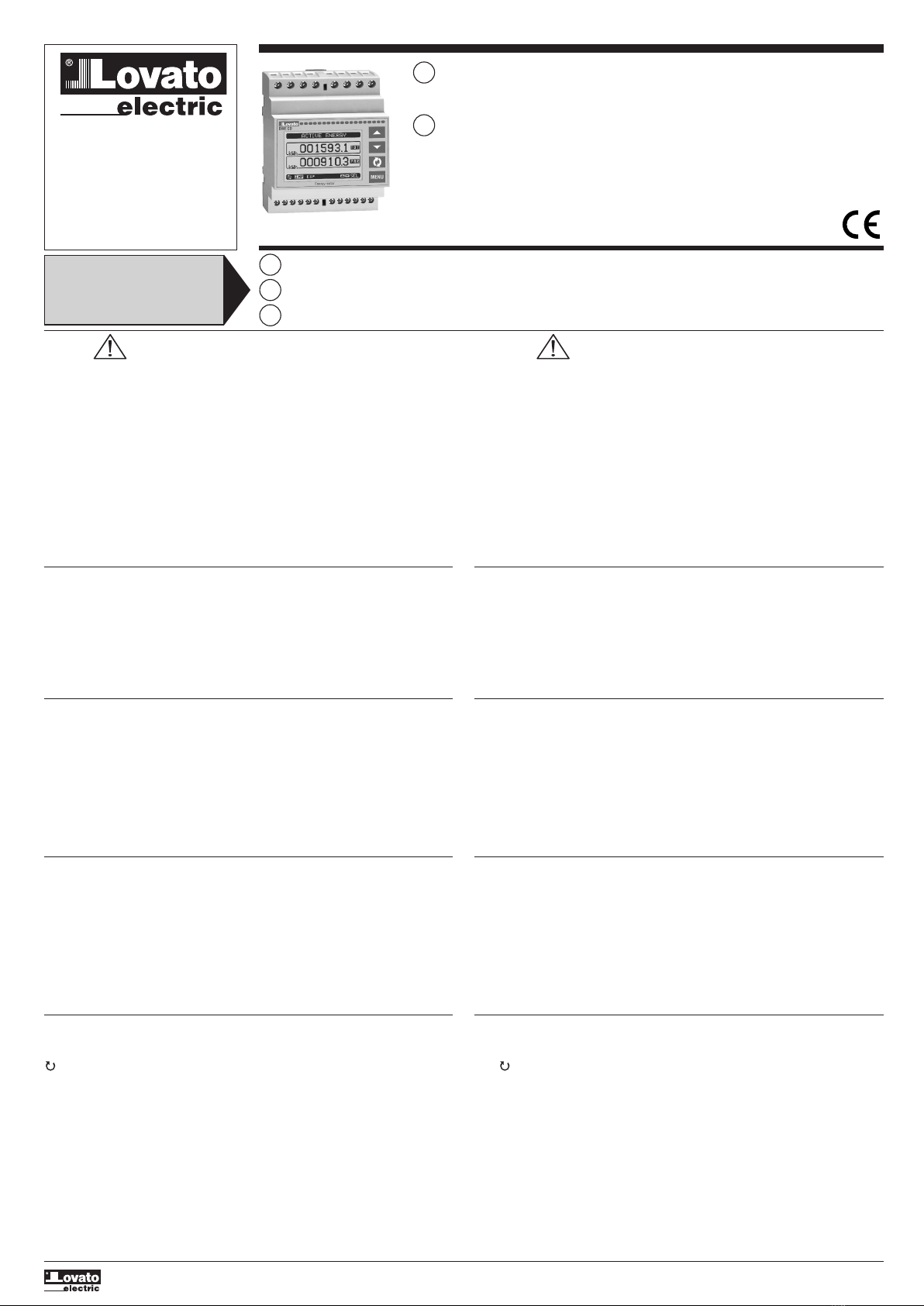
DATA CONCENTRATOR
Installation manual
GB
CONCENTRATORE DATI
Manuale d’installazione
I
WARNING!
– Carefully read the manual before the installation or use.
– This equipment is to be installed by qualified personnel, complying to current standards, to avoid
damages or safety hazards.
– Before any maintenance operation on the device, remove all the voltages from measuring and supply
inputs and short-circuit the CT input terminals.
–The manufacturer cannot be held responsible for electrical safety in case of improper use of the
equipment.
–Products illustrated herein are subject to alteration and changes without prior notice.
Technical data and descriptions in the documentation are accurate, to the best of our knowledge, but
no liabilities for errors, omissions or contingencies arising therefrom are accepted.
–A circuit breaker must be included in the electrical installation of the building. It must be installed
close by the equipment and within easy reach of the operator. It must be marked as the disconnecting
device of the equipment: IEC /EN 61010-1 § 6.11.2.
–Fit the instrument in an enclosure or cabinet with minimum IP40 degree protection.
– Clean the instrument with a soft dry cloth; do not use abrasives, liquid detergents or solvents.
INTRODUCTION
The DMECD data concentrator is a device that extends the potential of DME energy meters family,
providing a data collector function together with an interface to remote supervision systems.
The DMECD can be used also in several applications as a stand-alone product, to measure the
consumption of counters of various types, to measure the production of machinery etc, thanks to its
extreme configuration flexibility that has no equal in this kind of devices. The LCD graphic display offers
a user-friendly interface. The Infra-red optical port allows the expansion of the unit by means of the wide
range of EXM… expansion modules, allowing to support various types of communication and to connect
additional input channels.
DESCRIPTION
– Modular DIN-rail housing, 4U (72mm wide).
– Graphic LCD display, 128x80 pixels, white backlight, 4 grey levels.
– Membrane keyboard with 4 keys for visualization and setting.
– Easy and fast navigation.
– Texts for measures, setup and messages in 5 languages.
– 8 built-in contact input channels (max 14 with expansion).
– Built-in inputs organized as 4 couples insulated between them.
– 1 auxiliary AC input channel for selecting the tariff.
– Integrated RS-485 interface.
– Optical interface for a max of 3 expansion modules series EXM....
MAIN FUNCTIONS
– Management of max 14 completely programmable meters (alphanumerical description, unit of
measure, count increase coefficients).
– Resettable partial meters.
– Two-way (up / down) meter management.
– Count derivative management (indication of mean power, production speed, etc.).
– Display of count derivative trend graphs.
– Management of max 4 tariffs.
– Programmable I/O functions.
– Alarm management on exceeding thresholds.
– Programmable mathematical calculation functions (sums of meters, relations between quantities, etc.)
KEYBOARD FUNCTIONS
s
and
t
keys - Used to scroll display pages, to select among possible choices, and to modify settings
(increment-decrement).
key – Used to rotate through sub-pages, to confirm a choice, to switch between visualization
modes.
MENU key - Used to enter or exit from visualization and setting menus.
ATTENZIONE!!
– Leggere attentamente il manuale prima dell’utilizzo e l’installazione.
– Questi apparecchi devono essere installati da personale qualificato, nel rispetto delle vigenti normative
impiantistiche, allo scopo di evitare danni a persone o cose.
– Prima di qualsiasi intervento sullo strumento, togliere tensione dagli ingressi di misura e di
alimentazione e cortocircuitare i trasformatori di corrente.
–Il costruttore non si assume responsabilità in merito alla sicurezza elettrica in caso di utilizzo
improprio del dispositivo.
–I prodotti descritti in questo documento sono suscettibili in qualsiasi momento di evoluzioni o di
modifiche. Le descrizioni ed i dati a catalogo non possono pertanto avere alcun valore contrattuale.
–Un interruttore o disgiuntore va compreso nell’impianto elettrico dell’edificio. Esso deve trovarsi in
stretta vicinanza dell’apparecchio ed essere facilmente raggiungibile da parte dell’operatore. Deve
essere marchiato come il dispositivo di interruzione dell’apparecchio: IEC/ EN 61010-1 § 6.11.2.
– Installare lo strumento in contenitore e/o quadro elettrico con grado di protezione minimo IP40.
–Pulire lo strumento con panno morbido, non usare prodotti abrasivi, detergenti liquidi o solventi.
INTRODUZIONE
Il concentratore dati DMECD è un apparecchio che amplia le potenzialità di utilizzo della famiglia di
contatori di energia della serie DME, fornendo una funzione di raccolta dati ed interfaccia verso sistemi di
supervisione remota. Il DMECD può inoltre trovare numerose applicazioni come apparecchio stand-
alone, per la misurazione di consumi da contatori di diverso tipo, la misurazione della produzione di
macchine operatrici ecc., grazie alla sua estrema flessibilità di configurazione, che non ha eguali in
questo tipo di apparecchi. Il display grafico LCD consente una interfaccia utente intuitiva. La porta ottica
a raggi infrarossi consente l’espansione tramite la vasta gamma di moduli EXM… permettendo di
supportare vari tipi di comunicazione e di aggiungere canali di ingresso.
DESCRIZIONE
– Esecuzione modulare 4U (72mm) per guida DIN.
– Display LCD grafico 128x80 pixel, retroilluminato, 4 livelli di grigio.
– 4 tasti a membrana per visualizzazione ed impostazione.
– Navigazione rapida e semplice.
– Testi per misure, impostazioni e messaggi in 5 lingue.
– 8 canali di ingresso da contatto incorporati (max 14 con espansione).
– Ingressi unità base organizzati in 4 coppie isolate fra loro.
– 1 ingresso AC ausiliario per selezione tariffa.
– Interfaccia RS-485 integrata.
– Interfaccia ottica per max 3 moduli di espansione serie EXM… .
FUNZIONI PRINCIPALI
– Gestione di max 14 contatori completamente programmabili (descrizione alfanumerica, unità di
misura, coefficienti di incremento conteggio).
– Contatori parziali azzerabili.
– Gestione di contatori bidirezionali (up / down).
– Gestione di derivata di conteggio (indicazione potenza media, velocità di produzione ecc.).
– Visualizzazione di grafici trend della derivata di conteggio.
– Gestione di max 4 tariffe.
– Funzioni di I/O programmabili.
– Gestione di allarmi su superamento soglie.
– Funzioni matematiche di calcolo programmabili (somme di contatori, rapporti fra grandezze ecc.)
FUNZIONE DEI TASTI FRONTALI
Tasti
s
e
t
- Servono per lo scorrimento fra le pagine video, per la selezione fra le possibili scelte
presentate a display e per la modifica di impostazioni (incremento/decremento).
Tasto - Serve per lo scorrimento delle sotto-pagine, per confermare una scelta effettuata e per
passare da una modalità all’ altra di visualizzazione.
Tasto MENU - Serve per entrare o uscire dai vari menu sia di visualizzazione che di impostazione.
I
Available in Italian at www.LovatoElectric.com/I3111GBIE.pdf
E
Available in Spanish at www.LovatoElectric.com/I3111GBIE.pdf
GB
Available in English at www.LovatoElectric.com/I3111GBIE.pdf
The complete operating manual is
downloadable from website
www.lovatoelectric.com
Il manuale operativo completo è
scaricabile dal sito www.lovatoelectric.com
DME CD
I381 GB I 05 13 31100185
2
FUNCTIONS OF THE DATA CONCENTRATOR
–The DMECD can manage up to a maximum of 16 meters, called CNT01..16, each with a total (TOT)
and partial count (PAR) both resettable.
–The meters are completely programmable. For each meter it is possible to define the following
characteristics:
general meter enable
meter alphanumerical description
meter alphanumerical unit of measure
count increase signal (source)
count decrease signal (source)
increase/decrease coefficient
partial meter reset signal
total meter reset signal
derivative measure enable
unit of derivative measure
NOTE:
–With the default settings, the DMECD is already set for reading the energy count pulses leading from
the built-in static output in the devices of the DME series.
– By default, the DME Energy meters emit a pulse every 0.1 kWh (10 pulses per kWh). For this reason,
the default settings of the DMECD include:
Meter increase coefficient 0.1 (divisor 10)
Meter unit of measure kWh
– Also with regard to viewing the derivative (active power) the default settings make it possible to have
the correct indication expressed in kW.
Operand 1 Operator 1 Operand 2 Operator 2 Constant
CNT1 + CNT2 +0
1 - Unit of measure of derivative
2 - Unit of measure of counter
3 - Counter description
4 - Counter (meter) value
5 - Derivative (optional)
1 - Unità di misura derivata
2 - Unità di misura contatore
3 - Descrizione contatore
4 - Valore contatore
5 - Derivata (opzionle)
– The user can define to which page and sub-page the display must return to after a period of time has
elapsed without any keystroke.
– If needed, it is possible to set the data concentrator so that the display will remain always in the
position in which it has been left.
– To set these functions see menu M02 – Utility.
NOTE: Some of the pages listed above might not be viewed, if e the function viewed is not enabled.
VIEWING OF THE MEASUREMENTS
– The
s
and
t
keys scroll the pages showing the measures one at a time. The current page is
identified by the header bar.
– Some of the measures might not be viewed depending on the programming and connection of the
device.
– For each page, the key allows access to the sub-pages, the contents of which are shown in the
status-bar (last line of the display).
–For the main pages it is possible to view the present count with alphanumerical description of the
meter and of the corresponding unit of measure
Example of display page with numeric indication
FUNZIONI DEL CONCENTRATORE DATI
–Il DMECD può gestire fino ad un massimo di 16 contatori, denominati CNT01..16, ciascuno con un
conteggio totale (TOT) e parziale (PAR) entrambi azzerabili.
–I contatori sono completamente programmabili. Per ciascun contatore è possibile definire le seguenti
caratteristiche:
abilitazione generale del contatore
descrizione alfanumerica del contatore
unità di misura alfanumerica del contatore
segnale (sorgente) di incremento conteggio
segnale (sorgente) di decremento conteggio
coefficiente di incremento/decremento
segnale di azzeramento del contatore parziale
segnale di azzeramento del contatore totale
abilitazione misura derivata
unità di misura della derivata
NOTA:
–Con le impostazioni di default, il DMECD è già predisposto per la lettura degli impulsi di conteggio di
energia provenienti dalla uscita statica incorporata negli apparecchi della serie DME.
– Di default, gli Energy meters DME emettono un impulso ogni 0.1kWh (10 impulsi per kWh). Per
questa ragione, le impostazioni di default del DMECD prevedono:
Coefficiente di incremento del contatore 0.1 (divisore 10)
Unità di misura del contatore kWh
– Anche per quanto riguarda la visualizzazione della derivata (potenza attiva) le impostazioni di default
consentono di avere l’indicazione corretta espressa in kW.
Operando 1 Operatore 1 Operando 2 Operatore 2 Costante
CNT1 + CNT2 +0
VISUALIZZAZIONE DELLE MISURE
– I tasti
s
e
t
consentono di scorrere le pagine di visualizzazione misure una per volta. La pagina
attuale è riconoscibile tramite la barra del titolo.
– Alcune delle misure potrebbero non essere visualizzate in funzione della programmazione e del
collegamento dell’apparecchio .
– Per ogni pagina, il tasto consente di accedere a delle sotto-pagine, il cui contenuto è evidenziato
nella status-bar (ultima riga del display).
–Per le pagine principali, è possibile avere la visualizzazione del conteggio attuale con descrizione
alfanumerica del contatore e della relativa unità di misura.
Esempio di pagina contatori
TABLE OF DISPLAY PAGES
Selection with
s
and
t
Selection with
N° PAGE
SUB PAGES
1 COUNTER 01 - CNT01, DER01 TOT PAR
.....
2 COUNTER 16 - CNT16, DER16 TOT PAR
3 TREND GRAPH 1
.....
4 TREND GRAPH 16
5 COUNTER 01 TARIFFS - TAR1,TAR2,TAR3,TAR4,Σ
.....
6 COUNTER 16 TARIFFS - TAR1,TAR2,TAR3,TAR4,Σ
.....
7 MATH 01
.....
8 MATH 16
9 BOOLEAN LOGIC BOO1…BOO8
10 LIMIT THRESHOLDS LIM1…LIM8
11 ALARMS ALA1…ALA8
12 HOUR METER - Hr TOT, Hr PAR
13 EXPANSION MODULES
14
INFO-REVIIEWS-SERIAL NO. - MODEL, SW REV, HW REV, SERIAL no.
15 LOGO
– L’utente ha la possibilità di specificare su quale pagina e quale sottopagina il display deve ritornare
automaticamente dopo che è trascorso un tempo senza che siano premuti dei tasti.
– Volendo è anche possibile programmare il concentratore dati in modo che la visualizzazioni resti
sempre nella posizione in cui è stata lasciata.
– Per l’impostazione di queste funzioni vedere menu M02 – Utilità.
NOTA: Alcune delle pagine elencate sopra potrebbero non essere visualizzate, se la funzione visualizzata
non è abilitata.
TABELLA DELLE PAGINE DEL DISPLAY
Selezione con
s
e
t
Selezione con
N° PAGINE
SOTTOPAGINE
1 CONTATORE 01 - CNT01, DER01 TOT PAR
.....
2 CONTATORE 16 - CNT16, DER16 TOT PAR
3 GRAFICO TREND 1
.....
4 GRAFICO TREND 16
5 TARIFFAZIONE CONTATORE 01 - TAR1,TAR2,TAR3,TAR4,Σ
.....
6 TARIFFAZIONE CONTATORE 16 - TAR1,TAR2,TAR3,TAR4,Σ
.....
7 MATEMATICA 01
.....
8 MATEMATICA 16
9 LOGICA BOOLEANA BOO1…BOO8
10 SOGLIE LIMITE LIM1…LIM8
11 ALLARMI ALA1…ALA8
12 CONTAORE - Hr TOT, Hr PAR
13 MODULI ESPANSIONE
14
INFO-REVISIONI-SERIAL NR. - MODELLO,REV SW, REV HW,Nr. SERIE
15 LOGO
I381 GB I 05 13 31100185
3
MAIN MENU
–The main menu is made up of a group of graphic icons (shortcuts) that allow rapid access to
measurements and settings.
–Starting from normal viewing, press MENU key. The main menu screen is displayed.
–Press
s t
to select the required function. The selected icon is highlighted and the central part of
the display shows the description of the function.
– Press to activate the selected function.
– If some functions are not available, the correspondent icon will be disabled, that is shown in a light
grey colour.
–etc. - Shortcuts that allow jumping to the first page of that group. Starting
from that page it is still possible to move forward-backward in the usual way.
– - Open the password entry page, where it is possible to specify the numeric codes that unlock
protected functions (parameter setting, commands menu etc.).
–- Access point to the setup menu for parameter programming.
– - Access point to the commands menu, where the authorised user can execute some clearing-
restoring actions.
MENU PRINCIPALE
–Il menu principale è costituito da un insieme di icone grafiche che permettono l’accesso rapido alle
misure ed alle impostazioni.
–Partendo dalla visualizzazione misure normale, premere il tasto MENU. Il display visualizza il menu
rapido.
–Premere
s t
per selezionare la funzione desiderata. L’icona selezionata viene evidenziata e la scritta
nella parte centrale del display indica la descrizione della funzione.
– Premere per attivare la funzione selezionata.
– Se alcune funzioni non sono disponibili la corrispondente icona sarà disabilitata, cioè visualizzata in
colore grigio.
–ecc. - Agiscono come scorciatoie che consentono di velocizzare l’accesso alle
pagine di visualizzazione misure, saltando direttamente al gruppo di misure selezionato, partendo dal
quale ci si potrà spostare avanti e indietro come di consueto.
– - Impostazione del codice numerico che consente l’accesso alle funzioni protette
(impostazione dei parametri, esecuzione di comandi).
–- Punto di accesso alla programmazione dei parametri. Vedere il capitolo dedicato.
– - Punto di accesso al menu comandi, dove l’utente abilitato può eseguire una serie di azioni di
azzeramento e ripristino.
1 - Counter readings
2 - Trend graphs
3 - Tariffs
4 - Math variables
5 - Boolean logic
6 - Limit thresholds
7 - Alarm
8 - Hour couters
9 - Expansion modules
10 - Setup menu
11 - Commands menu
12 - Password entry
1 - Visualizzazione contatori
2 - Grafici trend
3 - Tariffazione
4 - Variabili matematiche
5 - Variabili booleane
6 - Soglie limite
7 - Allarmi
8 - Visualizzazione contaore
9 - Moduli di espansione
10 - Impostazioni (Setup)
11 - Menu comandi
12 - Inserimento password
PASSWORD ACCESS
– The password is used to enable or lock the access to setting menu (setup) and to commands menu.
– For brand-new devices (factory default), the password management is disabled and the access is free.
If instead the passwords have been enabled and defined, then to get access, it is necessary to enter
the password first, specifying the numeric code through the keypad.
– To enable password management and to define numeric codes, see setup menu.
– There are two access levels, depending on the code entered:
User-Level access - Allows clearing of recorded values but not editing of parameter set-up.
Advanced access level - Same rights of the user access plus parameter setting.
– From normal viewing, press MENU to recall the main menu, select the password icon and press .
– The display shows the screen in the figure.
ACCESSO TRAMITE PASSWORD
– La password serve per abilitare o bloccare l’accesso al menu di impostazione ed al menu comandi.
– Per gli apparecchi nuovi di fabbrica (default), la password è disabilitata e l’accesso è libero. Se invece
le password sono state abilitate, per ottenere l’accesso bisogna prima inserire il relativo codice di
accesso numerico.
– Per abilitare l’uso delle password e definire i codici di accesso fare riferimento al capitolo
impostazione parametri.
– Esistono due livelli di accesso, a seconda del codice inserito:
Accesso livello utente - consente l’azzeramento dei valori registrati ma non la modifica delle
impostazioni dell’apparecchio.
Accesso livello avanzato - stessi diritti dell’utente con in più la possibilità di modificare le
impostazioni.
– Dalla normale visualizzazione misure, premere MENU per richiamare il menu principale, quindi
selezionare l’icona password e premere .
– Compare la finestra di impostazione password in figura:
– Keys
s t
change the selected digit
– Key confirms the digit and moves to the next.
– Enter numeric code, then move on the key icon.
– If the password code entered matches the User access code or the Advanced access code, then the
correspondent unlock message is shown.
– Once unlocked the password, the access rights last until:
The device is powered off.
The device is reset (after quitting the setup menu).
The timeout period of two minutes elapses without any keystroke.
– To quit the password entry screen press MENU key.
– Con i tasti
s t
si cambia il valore della cifra selezionata.
– Con il tasto si conferma la cifra e ci si sposta a rotazione sulle successive.
– Inserire la password, quindi spostarsi sull’icona della chiave.
– Quando la password inserita corrisponde alla password livello Utente o livello Avanzato, compare il
relativo messaggio di sblocco.
– Una volta sbloccata la password, l’accesso rimane abilitato fino a che:
l’apparecchio viene disalimentato.
l’apparecchio viene resettato (in seguito all’uscita dal menu impostazioni).
trascorrono più di 2 minuti senza che l’operatore tocchi alcun tasto.
– Con il tasto MENU si abbandona l’impostazione password e si esce.
I381 GB I 05 13 31100185
4
EXPANDABILITY
–Thanks to its built-in optical infrared interface, the DMECD can be expanded with EXM series
modules.
–These modules have an optical interface on the left side for the connection to the base unit and a
second interface on the right side for the connection of an additional expansion module.
–It is possible to connect a maximum of 3 EXM modules.
– The EXM modules can be grouped in the following categories:
Communication modules
Digital I/O modules
Mixed modules – Communication + digital outputs
Memory modules.
–The modules can be connected to the base unit simply placing them side by side and then inserting
the dedicated clips. The insertion sequence is free.
ESPANDIBILITÀ
–Grazie alla sua interfaccia ottica a raggi infrarossi incorporata, il DMECD può essere espanso con dei
moduli aggiuntivi della serie EXM….
–Questi moduli sono a loro volta dotati di un’interfaccia ottica sul lato sinistro per il collegamento
all’unità base e di una seconda sul lato destro per il collegamento di un ulteriore modulo di
espansione.
– E’ possibile collegare ad un DMECD un massimo di 3 moduli EXM….
– I moduli EXM… si dividono nelle seguenti categorie:
moduli di comunicazione
moduli di I/O digitale
moduli misti Comunicazione + uscite digitali
moduli di memoria
–I moduli si collegano alla unità base semplicemente affiancandoli e inserendo le apposite clip fino ad
agganciarli a scatto.
–L’ordine di inserimento dei moduli è libero.
– When a DMECD is powered on, it automatically recognises the EXM modules that have been
mounted.
– If the system configuration has changed with respect to the last saved, (one module has been added
or removed), the base unit asks the user to confirm the new configuration. In case of confirmation,
the new configuration will be saved and will become effective, otherwise the mismatch will be shown
at every subsequent power-on of the data concentrator.
– The actual system configuration is shown in the dedicated page of the display (expansion modules),
where it is possible to see the number, the type and the status of the modules.
–The expansion I/O numbering is shown under each module.
– The status (energised/de-energised) of every single I/O and communication channel is highlighted in
reverse.
– Quando un DMECD viene alimentato, riconosce automaticamente i moduli EXM ad esso collegati.
– Se la configurazione del sistema è diversa rispetto all’ultima rilevata (è stato aggiunto o rimosso un
modulo), l’unità base chiede all’utente di confermare la nuova configurazione. In caso di conferma la
nuova configurazione verrà salvata e diventerà effettiva, altrimenti ad ogni messa in tensione verrà
segnalata la discordanza.
–La configurazione attuale del sistema è visualizzata nella apposita pagina del display (moduli
espansione), dove si vedono il numero, il tipo e lo stato dei moduli collegati.
– La numerazione degli I/O di espansione viene elencata sotto ogni modulo.
–Lo stato (attivato/disattivato) degli I/O e dei canali di comunicazione viene evidenziato con la scritta in
negativo.
1 - Base unit with built-in resources
2 - Type of the expansion module
3 - Status of the expansion
4 - Built-in inputs status
1 - Unità base e stato delle risorse
incorporate
2 - Tipo dei moduli di espansione
3 - Stato delle risorse di espansione
4 - Stato degli ingressi incorporati
ADDITIONAL RESOURCES
– The base unit DMECD has the following built-in resources:
8 counting inputs (INP1..INP8 – terminals I1.1…I4.2)
1 tariff selection input (INP15 – terminals T1-T2)
1 RS485 communication interface (COM1 – TR,A,B,SG)
– The EXM expansion modules provide additional resources that can be used through the dedicated
setup menus.
– In its maximum configuration, the DMECD can manage 16 inputs, 14 of which for counters
(INP1…INP14), one for tariff selection (INP15) and one reserved (INP16).
– The setup menus related to the expansions are always accessible, even if the expansion modules are
not physically fitted.
– Since it is possible to add more than one module of the same typology (for instance two
communication interfaces), the setup menus are multiple, identified by a sequential number.
– The following table indicates how many modules of each group can be mounted at the same time.
The total number of modules must be less or equal than 3.
RISORSE AGGIUNTIVE
– L’apparecchio base DMECD incorpora le seguenti risorse:
8 Ingressi di conteggio (INP1…INP8 – morsetti I1.1…I4.2)
1 Ingresso selezione tariffa (INP15 – morsetti T1-T2)
1 Interfaccia di comunicazione RS-485 (COM1 – TR,A,B,SG)
– I moduli di espansione EXM forniscono delle risorse aggiuntive che possono essere sfruttate tramite
gli opportuni menu di impostazione.
– Nella massima configurazione, il DMECD può gestire 16 ingressi, di cui max 14 ingressi di conteggio
(INP1..INP14), uno di selezione tariffa (INP15) e uno riservato (INP16).
– I menu di impostazione che riguardano le espansioni sono disponibili anche se i moduli non sono
fisicamente presenti.
– Dato che è possibile aggiungere più moduli della stessa tipologia (ad esempio due interfacce di
comunicazione) i relativi menu di impostazione sono multipli, identificati da un numero progressivo.
– Di seguito una tabella che indica quanti moduli di ogni tipo possono essere montati
contemporaneamente. Il numero totale di moduli deve essere < 3.
MODULE TYPE CODE FUNCTION MAX Nr.
COMMUNICATION EXM 10 10 USB 1
EXM 10 11 RS-232
EXM 10 12 RS-485
EXM 10 13 ETHERNET
DIGITAL I/O EXM 10 00 2 IN + 2 SSR 3
EXM 10 01 2 IN + 2 RELAYS
MIXED EXM 10 20 485 + 2 RELAYS 2
MEMORY EXM 10 30 EVENTS - DATA 1
TIPO MODULO CODICE FUNZIONE Nr. MAX
COMUNICAZIONE EXM 10 10 USB 1
EXM 10 11 RS-232
EXM 10 12 RS-485
EXM 10 13 ETHERNET
I/O DIGITALI EXM 10 00 2 IN + 2 SSR 3
EXM 10 01 2 IN + 2 RELE’
MISTI EXM 10 20 485 + 2 RELE’ 2
MEMORIA EXM 10 30 EVENTI - DATI 1
I381 GB I 05 13 31100185
5
PARAMETER SETTING (SET-UP)
–With normal viewing, press MENU to recall the General menu, then select icon and press
to open the setup menu screen.
–The display will show the table below, with the parameters grouped in sub-menus with a function-
related criteria .
–Select the required menu with
s t
keys and confirm with .
– To quit setup and go back to the readings viewing, press MENU.
IMPOSTAZIONE DEI PARAMETRI (SET-UP)
–Dalla normale visualizzazione misure, premere MENU per richiamare il menu principale,quindi
selezionare l’icona e premere per accedere al menu impostazioni.
–Viene visualizzata la tabella in figura, con la selezione dei sotto-menu di impostazione, nei quali sono
raggruppati tutti i parametri secondo un criterio legato alla loro funzione.
– Selezionare il menu desiderato tramite i tasti
s t
e confermare con .
–Per uscire e tornare alla visualizzazione misure premere MENU.
Code Menu Description
M01 COUNTERS (CNTn) Counters management
M02 UTILITY Language, backlight, display pages, etc.
M03 PASSWORD Access codes enabling
M04 HOUR METER Hour meter enabling
M05 TREND GRAPH Trend graph reading and scale
M06 COMMUNICATION (COMn) Communication ports parameters (DMG210)
M07 LIMIT THRESHOLDS (LIMn) Limit thresholds on readings
M08 ALARMS (ALAn) Alarm messages
M09 BOOLEAN LOGIC (BOOn) Boolean logic variables
M10 INPUTS (INPn) Digital inputs
M11 OUTPUTS (OUTn) Digital outputs
M12 MATHEMATICS (MATn) Mathematic functions
M13 PULSES (PULn) Count pulse generation
–The following table lists the available sub-menus:
– Select the sub-menu and press to show the parameters.
– Each parameter is shown with code, description and current setting value.
Code Menu Descrizione
M01 CONTATORI (CNTn) Gestione contatori
M02 UTILITA’ Lingua, luminosità, pagine display ecc.
M03 PASSWORD Abilitazione protezione accesso
M04 CONTAORE Abilitazione contaore
M05 GRAFICO TREND Definizione misura e scala grafico trend
M06
COMUNICAZIONE (COMn) COMCOMn
Porte di comunicazione
M07 SOGLIE LIMITE (LIMn) Soglie sulle misure
M08 ALLARMI (ALAn) Messaggi di allarme
M09 LOGICA BOOLEANA (BOOn) Combinazioni logica Booleana
M10 INGRESSI (INPn) Ingressi digitali
M11 USCITE (OUTn) Uscite digitali
M12 MATEMATICA (MATn) Funzioni matematiche
M13 IMPULSI (PULn) Generazione impulsi conteggio
–Nella seguente tabella sono elencati i sottomenu disponibili
– Selezionare il sotto-menu e premere il tasto per visualizzare i parametri.
– Tutti i parametri sono visualizzati con codice, descrizione, valore attuale.
1 - Parameter code
2 - Parameter description
3 - Present setting value
4 - Selected parameter
1 - Codice parametro
2 - Descrizione parametro
3 - Valore attuale
4 - Parametro selezionato
– To modify the setting of one parameter, select it and then press .
– If the Advanced level access code has not been entered, it will not be possible to enter editing page
and an access denied message will be shown.
– If instead the access rights are confirmed, then the editing screen will be shown.
– Se si vuole modificare il valore di un parametro, dopo averlo selezionato premere .
– Se non è stata immessa la password livello Avanzato, non sarà possibile accedere alla pagina di
modifica, e verrà visualizzato un messaggio di accesso negato.
– Se invece si ha l’accesso, verrà visualizzata la pagina di modifica.
1 - Selected parameter
2 - Minimum possible setting
3 - Graph bar of the value-range
4 - New value entered
5 - Maximum possible setting
6 - Factory default setting
1 - Parametro selezionato
2 - Minimo valore possibile
3 - Barra grafica valore-range
4 - Nuovo valore impostato
5 - Massimo valore possibile
6 - Valore di default di fabbrica
– When the editing screen is displayed, the parameter setting can be modified with
s
and
t
keys.
The screen shows the new setting, a graphic bar that shows the setting range, the maximum and
minimum values, the previous setting and the factory default.
– Pressing simultaneously
s
and
t
, the setting is set to factory default.
– During the entry of a text string, keys
s
and
t
are used to select the alphanumeric character
while is used to move the cursor along the text string. Pressing keys
s
and
t
simultaneously
will move the character selection straight to ‘A’.
– Press MENU to go back to the parameter selection. The entered value is stored.
– Press MENU again to save all the settings and to quit the setup menu. The data concentrator executes
a reset and returns to normal operation.
– If the user does not press any key for more than 2 minutes, the data concentrator leaves the setup
automatically and goes back to normal viewing.
– Quando si è in modalità modifica, il valore può essere modificato con
s
e
t
. Vengono visualizzati
anche una barra grafica che indica il range di impostazione, i valori minimi e massimi possibili, il
valore precedente e quello di default.
– Premendo contemporaneamente
s
e
t
l’impostazione viene riportata al valore di default di fabbrica.
– Durante l’impostazione di un testo, con i tasti
s
e
t
si seleziona il carattere alfanumerico e con
si sposta il cursore all’interno del testo. Premendo contemporaneamente
s
e
t
la selezione
alfanumerica si posiziona direttamente sul carattere ‘A’.
– Premere MENU per tornare alla selezione parametri. Il valore immesso rimane memorizzato.
– Premere di nuovo MENU per salvare i cambiamenti ed uscire dalla impostazione. Il concentratore dati
esegue un reset e ritorna in funzionamento normale.
– Se non vengono premuti tasti per 2 minuti consecutivi, il menu setup viene abbandonato
automaticamente e il concentratore dati torna alla visualizzazione normale.
I381 GB I 05 13 31100185
6
M01 - COUNTERS (CNTn, n=1..16) Default Range
P01.n.01 Counter viewing ON (CNT01..08) OFF-ON
OFF (CNT09..16)
P01.n.02 Counter description CNTn (Text – 16 chars)
P01.n.03 Counter unit of measure kWh+ (Text – 6 chars)
P01.n.04 Increment signal source INP (1...8) OFF-ON-INPx-LIMx-BOOx-REMx
OFF (1...15)
P01.n.05 Channel number (x) n 1-16
P01.n.06 Decrement signal source OFF OFF-ON-INPx-LIMx-BOOx-REMx
P01.n.07 Channel number (x) n 1-16
P01.n.08 Multiplier 1 1-1000
P01.n.09 Divider 10 1-1000
P01.n.10
Partial counter clearing signal
OFF OFF-ON-INPx-LIMx-BOOx-REMx
source
P01.n.11 Channel number (x) n 1-16
P01.n.12 Total counter clearing signal OFF OFF-ON-INPx-LIMx-BOOx-REMx
source
P01.n.13 Channel number (x) n 1-16
P01.n.14
Time period for derivative calculation
OFF OFF/ 1- 60 min
P01.n.15 Derivative multiplier 60 1-1000
P01.n.16 Derivative divider 1 1-1000
P01.n.17 Derivative unit of measure kW+ (Text – 6 chars)
PARAMETER TABLE
Note: This menu is divided into 16 sections, for counters CNT1..16
P01.n.01 - Enables the viewing of the counter.
P01.n.02 - Alphanumeric string, 16 characters long, that describes the counter.
P01.n.03 - Alphanumeric string, 16 characters long, that describes the unit of measure of the counter.
P01.n.04 - P01.n.0 - Define the signal that cause counter increment.
P01.n.06 - P01.n.07 - Define the signal that cause counter decrement.
P01.n.08 - P01.n.09 - Define the ratio between counted pulses and measure shown on display. For every
pulse counted, the associated counter will be incremented / decremented by a value equal to a (P01.n.08
/ P01.n.09).
P01.n.10 - P01.n.11 - Define the optional signal that clears the partial counter.
P01.n.12 - P01.n.13 - Like above, referred to total counter.
P01.n.14 - Enables the derivative measurement and its calculation time.
P01.n.1 - P01.n.16 - Define the derivative calculation ratio.
P01.n.17 - Alphanumeric string, 6 characters long, that describes the unit of measure of the derivative.
M02 - UTILITY U/M Default Range
P02.01 Language English English
Italiano
Francais
Espanol
Portoguese
P02.02 Display contrast % 50 0-100
P02.03 High backlight level % 100 0-100
P02.04 Low backlight level % 30 0-50
P02.05 Low backlight delay sec 30 5-600
P02.06 Default page return sec 60 OFF / 10-600
P02.07 Default page VL-L VL-L / VL-N ...
P02.08 Default sub-page INST INST / HI / LO /
AVG / MD /GRAPH /
1-8
P02.09 Display update time sec 0.5 0.1 - 5.0
P02.06 – If set to OFF the display always remains in the page where the user left it. If set to a time delay,
after that time the display page goes back to page set in P02.07.
P02.07 – Number of the page to which the display returns automatically after time specified by P02.06
has elapsed from the last keystroke.
P02.08 – Sub-page type to which the display returns after P02.06 has elapsed.
P03.01 – If set to OFF, password management is disabled and the access to setup parameters and
command menu is allowed.
P03.02 – When P.03.01 enabled, value to be specified to get user access.
P03.03 – Like P03.02, but referred to advanced access.
M03 - PASSWORD U/M Default Range
P03.01 Enable passwords OFF OFF-ON
P03.02 User level password 1000 0-9999
P03.03 Advanced level password 2000 0-9999
M01 - CONTATORI (CNTn, n=1..16) Default Range
P01.n.01 Visualizzazione contatore ON (CNT01..08) OFF-ON
OFF (CNT09..16)
P01.n.02 Descrizione del contatore CNTn (Testo – 16 caratteri)
P01.n.03 Unità di misura contatore kWh+ (Testo – 6 caratteri)
P01.n.04 Sorgente incremento conteggio INP (1...8) OFF-ON-INPx-LIMx-BOOx-REMx
OFF (1...15)
P01.n.05 Numero canale (x) n 1-16
P01.n.06 Sorgente decremento conteggio OFF OFF-ON-INPx-LIMx-BOOx-REMx
P01.n.07 Numero canale (x) n 1-16
P01.n.08 Moltiplicatore 1 1-1000
P01.n.09 Divisore 10 1-1000
P01.n.10 Sorgente di azzeramento contatore OFF OFF-ON-INPx-LIMx-BOOx-REMx
parziale
P01.n.11 Numero canale (x) n 1-16
P01.n.12 Sorgente di azzeramento contatore OFF OFF-ON-INPx-LIMx-BOOx-REMx
totale TOT
P01.n.13 Numero canale (x) n 1-16
P01.n.14 Tempo di calcolo derivata OFF OFF/ 1- 60 min
P01.n.15 Moltiplicatore derivata 60 1-1000
P01.n.16 Divisore derivata 1 1-1000
P01.n.17 Unità di misura derivata kW+ (Testo – 6 caratteri)
TABELLA PARAMETRI
Nota: questo menu è diviso in 16 sezioni, per i contatori CNT1..16
P01.n.01 - Abilita la visualizzazione del contatore.
P01.n.02 - Stringa libera con lunghezza max 16 caratteri che descrive il contatore.
P01.n.03 - Stringa libera con lunghezza max 6 caratteri che descrive l’unità di misura del contatore.
P01.n.04 - P01.n.0 - Definiscono il segnale che provoca l’incremento del conteggio.
P01.n.06 - P01.n.07 - Definiscono il segnale che provoca il decremento del conteggio.
P01.n.08 - P01.n.09 - Definiscono il coefficiente di conversione fra il numero di impulsi conteggiati e la
misura mostrata sul display. Per ogni impulso conteggiato, il contatore associato verrà incrementato o
decrementato di una quantità uguale a (P01.n.08 / P01.n.09).
P01.n.10 - P01.n.11 - Definiscono il segnale opzionale che, quando attivato, azzera il contatore parziale.
P01.n.12 - P01.n.13 - Come sopra, riferito al contatore totale.
P01.n.14 - Abilita la visualizzazione della derivata del contatore e ne definisce il tempo di calcolo.
P01.n.1 - P01.n.16 - Definiscono il coefficiente di calcolo della derivata.
P01.n.17 - Stringa libera con lunghezza max 6 caratteri che descrive l’unità di misura della derivata di
conteggio.
M02 - UTILITA’ UdM Default Range
P02.01 Lingua English English
Italiano
Francais
Espanol
Portoguese
P02.02 Contrasto LCD % 50 0-100
P02.03 Intensità retroilluminazione display % 100 0-100
alta
P02.04 Intensità retroilluminazione display % 30 0-50
bassa
P02.05 Tempo passaggio a sec 30 5-600
retroilluminazione bassa
P02.06 Ritorno a pagina di default sec 60 OFF / 10-600
P02.07 Pagina di default VL-L VL-L / VL-N ...
P02.08 Sotto-pagina di default INST INST / HI / LO /
AVG / MD /GRAPH /
1-8
P02.09 Tempo di aggiornamento display sec 0.5 0.1 - 5.0
P02.06 – Se impostato ad OFF il display rimane sempre nella pagina dove è stato lasciato dall’utente. Se
impostato ad un valore, dopo questo tempo il display ritorna alla pagina impostata con P02.07.
P02.07 – Numero della pagina alla quale il display ritorna automaticamente una volta che è trascorso il
tempo P02.06 dall’ultima pressione di un tasto.
P02.08 – Tipo di sotto-pagina alla quale il display torna dopo trascorso P02.06.
P03.01 – Se impostato ad OFF, la gestione delle password è disabilitata e l’accesso alle
impostazioni e al menu comandi è libero.
P03.02 – Con P03.01 attivo, valore da specificare per attivare l’accesso a livello utente. Vedere
capitolo Accesso tramite password.
P03.03 – Come P03.02, riferito all’accesso livello Avanzato.
M03 - PASSWORD UdM Default Range
P03.01 Utilizzo password OFF OFF-ON
P03.02 Password livello Utente 1000 0-9999
P03.03 Password livello Avanzato 2000 0-9999
NOTE: Per i successivi menù vedi manuale operativo completo.NOTE: For subsequent menus, see instructions manual.
I381 GB I 05 13 31100185
7
COMMANDS MENU
–The commands menu allows executing some occasional operations like reading peaks resetting,
counters clearing, etc.
–If the Advanced level password has been entered, then the commands menu allows executing the
automatic operations useful for the device configuration.
– The following table lists the functions available in the commands menu, divided by the access level
required.
Code COMMAND ACCESS LEVEL DESCRIPTION
User Advanced
C.01 RESET PARTIAL COUNTERS llClears counters
C.02 RESET PARTIAL HOUR METER llClears partial hour meter
C.03 RESET TARIFFS llClears energy meter tariff
C.04 RESET ALARMS llClears alarms with latch
C.05 RESET LIMITS llClears limit thresholds with
latch
C.10 RESET TOTAL COUNTERS lClears counters
C.11 RESET TOTAL HOUR METER lClears total hour meter
C.12 PARAMETERS TO DEFAULT lAll setup parameters are reset
to factory default value
C.13 PARAMETERS BACKUP lSaves a backup copy of all
setup parameters
C.14 PARAMETERS RESTORE lRestores the setup
parameters to backup values
–Once the required command has been selected, press to execute it. The device will prompt for a
confirmation. Pressing again, the command will be executed.
–To cancel the command execution press MENU.
–To quit command menu press MENU.
MENU COMANDI
–Il menu comandi permette di eseguire operazioni saltuarie quali azzeramenti di misure, contatori,
allarmi ecc.
–Se è stata immessa la password per accesso avanzato, allora tramite il menu comandi è anche
possibile effettuare delle operazioni automatiche utili ai fini della configurazione dello strumento.
– Nella seguente tabella sono riportate le funzioni disponibili con il menu comandi, divise a seconda del
livello di accesso necessario.
Cod. COMANDO
LIVELLO ACCESSO
DESCRIZIONE
Utente Avanzato
C.01 AZZERAMENTO CONTATORI PARZIALI llAzzera i contatori parziali
C.02 AZZERAMENTO CONTAORE PARZIALI llAzzeramento dei contaore
parziali
C.03 AZZERAMENTO TARIFFE llAzzeramento contatori tariffe
C.04 AZZERAMENTO ALLARMI llAzzeramento allarmi con
memoria
C.05 AZZERAMENTO LIMITI llAzzeramento soglie limite con
memoria
C.10 AZZERAMENTO CONTATORI TOTALI lAzzera i contatori totali.
C.11 AZZERAMENTO CONTAORE TOTALI lAzzeramento dei contaore totali
C.12 PARAMETRI A DEFAULT lRipristina tutte le impostazioni
ai valori di default di fabbrica
C.13 BACKUP PARAMETRI lSalva una copia di sicurezza
(backup) delle impostazioni
C.14 RIPRISTINO PARAMETRI lRicarica le impostazioni dalla
copia di sicurezza
– Once the required command has been selected, press to execute it. The device will prompt for a
confirmation. Pressing again, the command will be executed.
–To cancel the command execution press MENU.
–To quit command menu press MENU.
MECHANICAL DIMENSIONS [mm] AND TERMINAL ARRANGEMENT DIMENSIONI MECCANICHE [mm] E DISPOSIZIONE MORSETTI
SGA1 A2 T1 T2 ATR B
72.0
90.0
45.0
58.0
43.7
5.0
WIRING DIAGRAMS SCHEMI DI CONNESSIONE
2 x 4 groups
I4.1
COM2
COM1
I1.2
I1.1
COM4
COM3
Insulated inputs
I2.2
I2.1
I3.2
I3.1
I4.2
100...240VAC
T1
AUX
Supply
A2
A1
110...250VDC
--- +
100...240VAC
Tariff
Input
T2
RS485
A
TR
B
110VDC
--- +
SG
F1AF1A
Input signal from NPN output - Ingresso da dispositivo con uscita NPN Input from LOVATO DME… - Ingresso da apparecchi DME.... Lovato
Term. Input
I1.1 INP1
I1.2 INP2
I2.1 INP3
I2.2 INP4
I3.1 INP5
I3.2 INP6
I4.1 INP7
I4.2 INP8
T1-T2 INP15
COM1
I1.2
I1.1
A1
A2
AUX
Supply
DME..... 1
DME..... 2
SO-
SO-
COM1
SO+
I1.1
SO+
I1.2
A2
A1
Supply
AUX
Mors. Ingr.
I1.1 INP1
I1.2 INP2
I2.1 INP3
I2.2 INP4
I3.1 INP5
I3.2 INP6
I4.1 INP7
I4.2 INP8
T1-T2 INP15
I381 GB I 05 13 31100185
8
TECHNICAL CHARACTERISTICS
Auxiliary supply
Rated voltage Us 100 - 240V
~
110 - 250V
Operating voltage range 85 - 264V
~
93.5 - 300V
Nominal frequency 50 – 60Hz
Operating frequency range 45 - 66Hz
Power consumption/dissipation 8.8VA 3.6W
Immunity time for microbreakings ≥50ms
Counter inputs
Number of Inputs 8
Inputs separation 2 x 4 couples (insulated between them 500VRMS)
Input type Negative (NPN)
Voltage present on the inputs 15V max
Current input 18mA max 15mA typical
“Input high” voltage ≥7.6V
“Input low” voltage ≤2V
Maximum frequency 2000Hz
Tariff command circuit
Rated voltage Uc 100 - 240V
~
110V
Operating voltage range 85 - 264V
~
93.5 - 140V
Rated frequency 50 - 60Hz
Operating frequency range 45 - 66Hz
Power consumption/dissipation 0.25VA / 0.18W
RS48 Serial interface
Baud-rate Programmable 1200…38400 bps
Insulation 1500V
~
towards counter inputs
Double insulation toward supply and tariff inputs
Ambient conditions
Operating temperature -20 - +55°C
Storage temperature -30 - +80°C
Relative humidity <80% (IEC/EN 60068-2-70)
Maximum pollution degree 2
Overvoltage category III
Altitude ≤2000m
Climatic sequence Z/ABDM (IEC/EN 60068-2-61)
Shock resistance 15g (IEC/EN 60068-2-27)
Vibration resistance 0.7g (IEC/EN 60068-2-6)
Insulation voltage
Rated insulation voltage Ui 250V
~
Rated impulse withstand voltage Uimp 6.5kV
Power frequency withstand voltage 3.6kV
Auxiliary supply and Tariff input and RS48 connections
Type of terminal Screw (fixed)
Number of terminals 2 for Aux supply
2 for tariff input
4 for RS485
Conductor cross section (min… max) 0.2 - 4.0 mm2(24 - 12 AWG)
Tightening torque 0.8Nm (7lbin)
Counter Input connections
Type of terminal Screw (fixed)
Number of terminals 12
Conductor cross section (min… max) 0.2…2.5 mm² (24 - 12 AWG)
Tightening torque 0.44 Nm (4 lbin)
Housing
Version 4 modules (DIN 43880)
Mounting 35mm DIN rail (IEC/EN 60715)
or by screw using extractible clips
Material Polyamide RAL7035
Degree of protection IP40 on front / IP20 terminals
Weight 315g
Certifications and compliance
Certifications cULus
Compliant with standards IEC/EN 61010-1, IEC/EN 61000-6-2, IEC/EN 61000-6-3
UL61010-1 and CSA C22.2 N° 61010-1
GB
CARATTERISTICHE TECNICHE
Alimentazione ausiliaria
Tensione nominale Us 100 - 240V
~
110 - 250V
Limiti di funzionamento 85 - 264V
~
93,5 - 300V
Frequenza nominale 50 - 60Hz
Limiti di funzionamento 45 - 66Hz
Potenza assorbita/dissipata 8,8VA 3,6W
Tempo di immunità alla microinterruzione ≥50ms
Ingressi contatori
Numero di ingressi 8
Separazione ingressi 2 x 4 coppie (isolate fra loro 500VRMS)
Tipo di ingresso Negativo (NPN)
Tensione presente sugli ingressi 15V max
Corrente d’ingresso 18mA max 15mA tipico
Segnale d’ingresso alto ≥7,6V
Segnale d’ingresso basso ≤2V
Frequenza massima 2000Hz
Circuito di comando tariffa
Tensione nominale Uc 100 - 240V
~
110V
Limiti di funzionamento 85 - 264V
~
93,5 - 140V
Frequenza nominale 50 - 60Hz
Limiti di funzionamento 45 - 66Hz
Potenza assorbita/dissipata 0,25VA / 0,18W
Interfaccia seriale RS48
Baud-rate Programmabile 1200 - 38400 bps
Isolamento 1500V
~
verso ingressi contatori
Doppio isolamento verso alimentazione e
ingresso tariffazione
Condizioni ambientali
Temperatura d’impiego -20 - +55°C
Temperatura di stoccaggio -30 - +80°C
Umidità relativa <80% (IEC/EN 60068-2-70)
Grado di inquinamento massimo 2
Categoria dì sovratensione III
Altitudine ≤2000m
Sequenza climatica Z/ABDM (IEC/EN 60068-2-61)
Resistenza agli urti 15g (IEC/EN 60068-2-27)
Resistenza alle vibrazioni 0.7g (IEC/EN 60068-2-6)
Tensione di isolamento
Tensione nominale d’isolamento Ui 250V
~
Tensione nominale di tenuta impulso Uimp 6,5kV
Tensione di tenuta a frequenza d’esercizio 3,6kV
Connessioni circuito alimentazione/ingresso tariffa / RS48
Tipo di morsetti A vite (fissi)
N° morsetti 2 per alimentazione
2 per ingresso tariffa
4 per RS485
Sezione conduttori (min e max) 0,2 - 4.0 mm2(24 - 12 AWG)
Coppia di serraggio mors. 0,8Nm (7lbin)
Connessioni ingresso contatori
Tipo di morsetti A vite (fissi)
N° morsetti 12
Sezione conduttori (min e max) 0,2 - 2,5 mm2(24 - 12 AWG)
Coppia di serraggio mors. 0.44 Nm (4 lbin)
Contenitore
Esecuzione 4 moduli (DIN 43880)
Montaggio Guida 35mm (IEC/EN60715)
o a vite a mezzo clip estraibili
Materiale Poliammide RAL 7035
Grado di protezione IP40 sul fronte / IP20 connessioni
Peso 315g
Omologazioni e conformità
Omologazioni cULus
Conformità a norme IEC/EN 61010-1, IEC/EN 61000-6-2, IEC/EN 61000-6-3
UL61010-1 e CSA C22.2 N° 61010-1
I

Other LOVATO ELECTRIC Measuring Instrument manuals

LOVATO ELECTRIC RGAM42 User manual

LOVATO ELECTRIC

LOVATO ELECTRIC RGAM42 User manual

LOVATO ELECTRIC DME D305T2MID User manual

LOVATO ELECTRIC

LOVATO ELECTRIC DME D305T2MID User manual

LOVATO ELECTRIC DME D110T1 User manual

LOVATO ELECTRIC

LOVATO ELECTRIC DME D110T1 User manual

LOVATO ELECTRIC DMED301MID User manual

LOVATO ELECTRIC

LOVATO ELECTRIC DMED301MID User manual

LOVATO ELECTRIC DME D122MID User manual

LOVATO ELECTRIC

LOVATO ELECTRIC DME D122MID User manual

LOVATO ELECTRIC DME D310 T2 MID User manual

LOVATO ELECTRIC

LOVATO ELECTRIC DME D310 T2 MID User manual

LOVATO ELECTRIC DME D110T1 User manual

LOVATO ELECTRIC

LOVATO ELECTRIC DME D110T1 User manual

LOVATO ELECTRIC DME D300 T2 User manual

LOVATO ELECTRIC

LOVATO ELECTRIC DME D300 T2 User manual

LOVATO ELECTRIC DMED302 User manual

LOVATO ELECTRIC

LOVATO ELECTRIC DMED302 User manual

LOVATO ELECTRIC DME D111 User manual

LOVATO ELECTRIC

LOVATO ELECTRIC DME D111 User manual

LOVATO ELECTRIC DME D100 T1 User manual

LOVATO ELECTRIC

LOVATO ELECTRIC DME D100 T1 User manual

LOVATO ELECTRIC DME D100 T1 User manual

LOVATO ELECTRIC

LOVATO ELECTRIC DME D100 T1 User manual

LOVATO ELECTRIC DME D330MID User manual

LOVATO ELECTRIC

LOVATO ELECTRIC DME D330MID User manual

LOVATO ELECTRIC DMK 15 User manual

LOVATO ELECTRIC

LOVATO ELECTRIC DMK 15 User manual

LOVATO ELECTRIC DMK 02 User manual

LOVATO ELECTRIC

LOVATO ELECTRIC DMK 02 User manual

LOVATO ELECTRIC DMED301MID User manual

LOVATO ELECTRIC

LOVATO ELECTRIC DMED301MID User manual

LOVATO ELECTRIC LOVATO ELECTRIC User manual

LOVATO ELECTRIC

LOVATO ELECTRIC LOVATO ELECTRIC User manual

LOVATO ELECTRIC DMED301 User manual

LOVATO ELECTRIC

LOVATO ELECTRIC DMED301 User manual

LOVATO ELECTRIC DMG7000 User manual

LOVATO ELECTRIC

LOVATO ELECTRIC DMG7000 User manual

LOVATO ELECTRIC DMED302MID User manual

LOVATO ELECTRIC

LOVATO ELECTRIC DMED302MID User manual

LOVATO ELECTRIC DME D120 T1 User manual

LOVATO ELECTRIC

LOVATO ELECTRIC DME D120 T1 User manual

LOVATO ELECTRIC DME D110T1 User manual

LOVATO ELECTRIC

LOVATO ELECTRIC DME D110T1 User manual

LOVATO ELECTRIC DMED301MID User manual

LOVATO ELECTRIC

LOVATO ELECTRIC DMED301MID User manual

LOVATO ELECTRIC DME D310 T2 MID User manual

LOVATO ELECTRIC

LOVATO ELECTRIC DME D310 T2 MID User manual

Popular Measuring Instrument manuals by other brands

Pfeiffer Vacuum HPT 200 operating instructions

Pfeiffer Vacuum

Pfeiffer Vacuum HPT 200 operating instructions

OSELA COMPACT LASER instruction manual

OSELA

OSELA COMPACT LASER instruction manual

Fluidwell F115-P Operation manual

Fluidwell

Fluidwell F115-P Operation manual

PCB Piezotronics J356A43 Installation and operating manual

PCB Piezotronics

PCB Piezotronics J356A43 Installation and operating manual

Rice Lake 480 Legend Series Operation manual

Rice Lake

Rice Lake 480 Legend Series Operation manual

Endress+Hauser Prosonic T FMU 130 operating manual

Endress+Hauser

Endress+Hauser Prosonic T FMU 130 operating manual

Foss NIRS DA1650 user manual

Foss

Foss NIRS DA1650 user manual

Sonotec SONAPHONE RD operating manual

Sonotec

Sonotec SONAPHONE RD operating manual

Tektronix Keithley SourceMeter 2470 Reference manual

Tektronix

Tektronix Keithley SourceMeter 2470 Reference manual

AKO AKO-59810 instruction manual

AKO

AKO AKO-59810 instruction manual

biochrom Ultrospec 50 user manual

biochrom

biochrom Ultrospec 50 user manual

Circutor CVM k2 manual

Circutor

Circutor CVM k2 manual

Danfoss 40 installation guide

Danfoss

Danfoss 40 installation guide

PCB Piezotronics 080B185 Installation and operating manual

PCB Piezotronics

PCB Piezotronics 080B185 Installation and operating manual

Konica Minolta CM-2600d instruction manual

Konica Minolta

Konica Minolta CM-2600d instruction manual

Micromeritics TriStar II 3020 Operator's manual

Micromeritics

Micromeritics TriStar II 3020 Operator's manual

Dillon FI-127 manual

Dillon

Dillon FI-127 manual

MeiTrack T466G user guide

MeiTrack

MeiTrack T466G user guide

manuals.online logo
manuals.online logoBrands
  • About & Mission
  • Contact us
  • Privacy Policy
  • Terms and Conditions

Copyright 2025 Manuals.Online. All Rights Reserved.