METIEC MT300MIX Specification sheet
HCLH/SOP-YF-072-108
Gas Monitoring Series
MT300MIX
Operation and Installation Manual

B1-MT300MIX
1
[Manufacturer]: Wuhan Huchuang Union Technology Co., Ltd.
[Production Address]: No.1 Workshop, 1F, Building B10, Wuhan Hi-Tech Medical Device Park, No. 818 Gaoxin
Avenue, East Lake Hi-Tech Development Zone, Wuhan, Hubei, China
[After-Sales Service Unit]: Wuhan Huchuang Union Technology Co., Ltd.
Date of Approval and Revision: March 1, 2021

B1-MT300MIX
2
Contents
1 Overview .................................................................................................................................................................3
1.1 Operation Instructions of Manual.................................................................................................................3
1.2 Overview ......................................................................................................................................................3
1.3 Environmental Requirements .......................................................................................................................3
1.4 Environmental Protection Instructions .........................................................................................................3
2 Structure Features and Equipment Parameters........................................................................................................4
2.1 Structure Features.........................................................................................................................................4
2.2 Equipment Parameters..................................................................................................................................6
3 Basic Operation Instructions....................................................................................................................................7
3.1 Power-On for Use.........................................................................................................................................7
3.2 Operation Instructions of Buttons.................................................................................................................8
4 Installation Instructions ........................................................................................................................................ 16
4.1 Installation Method 1................................................................................................................................. 16
4.2 Installation Method 2................................................................................................................................. 17
5 Precautions............................................................................................................................................................ 18
6 FCC Warning..................................................................................................................................................... 18

B1-MT300MIX
3
1Overview
1.1 Operation Instructions of Manual
1.1.1 It is not allowed to print or disclose any content of this Manual, including pictures and audio
products, under any name without the consent of Huchuang Union;
1.1.2 The equipment operator may copy some sections of this Operation Manual for internal use only,
such as for instructing the user how to deal with emergencies. These sections are clearly listed in
the catalogue of this manual;
1.1.3 Wuhan Huchuang Union Technology Co., Ltd. reserves the copyright of the Manual. The manual
contains the information protected by copyright laws. No part of the Manual is allowed to be
copied and sent to the users without the prior written permission of the copyright holder;
1.1.4 The contents of the Manual are subject to change without prior notice.
1.2 Overview
MT300MIX device is used to detect the concentrations of CO2and O2in premixed gas. It is generally
connected to the end of the gas path to detect the gas regularly, display the detected concentration data on the
display screen of the local machine, and upload it to the cloud server through wireless technology at the same
time.
The equipment has the function of leakage detection: When the equipment leaks, the audio and video
alarm system of the equipment can send out alarm sound and automatically close the intake valve. In order to
further ensure that the equipment does not leak, a manual valve is installed outside the equipment. If there is a
leak alarm, the user can manually close the intake valve.
The device has the low gas pressure detection function: When the gas pressure in the device is less than a
certain value, it will trigger the sound and light alarm of low pressure, reminding the user the low gas pressure.
The device is powered through the power adapter. The 1000mAh lithium battery built in the device can
only provide the power supply to the device for a short time when being disconnected from the adapter, so the
device cannot work under the condition of disconnection from the adapter for a long time; in addition, the
equipment has power failure alarm function.
When MT300MIX is installed and used for the first time, it is necessary to add the sampling frequency
(operated by professional engineers) in order to empty the excess air inside the device in a short time and
ensure the accuracy of premixed gas concentration detection.
Note:
1) The higher the sampling frequency (55 minutes by default) is, the longer the intake time will be (10 seconds
by default), and the larger the gas consumption will be.
2) The wireless transmission distance should not exceed 3 rooms.
1.3 Environmental Requirements
1.3.1 Only for indoor use, no high temperature, moisture, water or dust;
1.3.2 Atmospheric pressure: 70kPa~105kPa; Working ambient temperature: 0℃~+50℃;
1.3.3 Storage ambient temperature: 0℃~+50℃; relative humidity in the working environment: ≤80%
(non-condensing);
1.3.4 Power adapter (input: AC100V ~ 240V, 50/60Hz; output: 5V, 2.1A, 10.5W);
1.4 Environmental Protection Instructions

B1-MT300MIX
4
1.4.1 MT300MIX device contains reusable materials, and its components can be recycled after being
cleaned and sterilized.
1.4.2 During recycling and handling MT300MIX, it is recommended that the company's technical
personnel dismantle it and recycle it according to different waste groups.
1.4.3 According to national regulations, the compositions of the main raw materials of MT300MIX shall
be are shown in (Table 1).
Table 1 Compositions of Main Raw Materials of MT300MIX
Name
Composition
Casing
ABS+PC
Cover plate
Cold-rolled sheet
Side plate
Aluminum alloy
Battery
Polymer lithium battery
PCB
Including electrical components
2Structure Features and Equipment Parameters
2.1 Structure Features
a) Data Display Screen
It displays the concentrations monitored of CO2and O2; the heartbeat state of the device
running (the flash rate) is displayed on the upper left corner; the internal pressure, the air inlet
flow and the CO2concentration of the device are displayed on the upper right corner.
b) Buttons
Pressing buttons; each button has a corresponding function, you can carry out related operations
through buttons; buttons are generally operated by engineers.
a
b
B1-MT300MIX
5
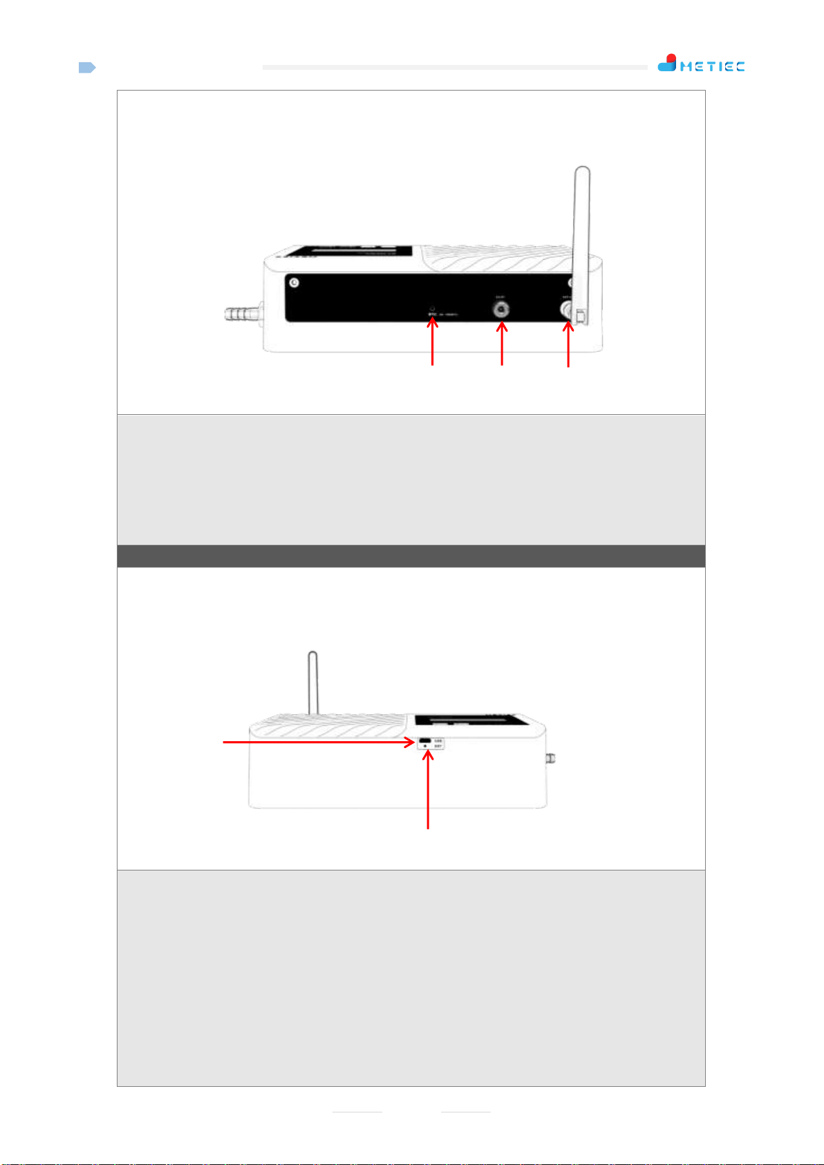
c) Power Interface
Equipped with a 5V/2Apower adapter.
d) Antenna
e) Gas Outlet
Refers to the gas outlet of the device. After the solenoid valve of the device is opened for the intake
detection, excess gas will be discharged through the outlet. Do not block the gas outlet.
f) Upgrade Debugging Port
Micro USB interface; it has 2 functions: Firstly, it can be used for program upgrade: The
special serial cable customized by the company is used for upgrading program instead of
Micro USB cable; secondly, it is used to modify parameters: The special serial cable
customized by the company shall be used for modifying parameters instead of Micro USB
cable; it needs to work with the modification software of " Huchuang Union Wireless Slaver
Debugging Platform.exe".
g) Reset Button (Pin-socket type)
Refers to the emergency reset hole of the device; the whole system can be reset through the
ejector pin here when the equipment breaks down.
e
c
d
g
f

B1-MT300MIX
6
h) Gas Inlet
i) Power Switch
j) Manual Ball Valve
Refers to the manual valve of the gas inlet pipe; in case of equipment leakage alarm, the user
can manually close this valve to ensure that the equipment will not leak.
2.2 Equipment Parameters
Table 2 MT300MIX Parameters
Item
Parameter
Overall dimensions
230mm*126mm*56mm
Weight
1367g
Transmission method
Wireless
Working frequency band
425-445MHz
Transmission distance
1200 m in open area, 1000 m in streets, about 300 m inside
buildings (not shielded by metal objects) under the transmission
rate of 10Kbps
h
i
j

B1-MT300MIX
7
Sensor
O2sensor, CO2 sensor
Detection resolution of
O2concentration
0.01%
Detection accuracy of
O2concentration
±0.2%
Detection range of O2
concentration
0%~30%
Detection resolution of
CO2concentration
0.01%
Detection accuracy of
CO2concentration
±0.2%
Detection range of CO2
concentration
0%~10%
Power failure alarm
Audible and visual alarm
Battery
1000mAh, providing the power supply for more than 2 hours after
power failure in fully charged state
Display screen
2.23 inches
Data refresh frequency
of display screen
1 second/ time
Equipment status upload
frequency
3 min/time (modifiable) by default
Concentration sampling
frequency
55 min/time (modifiable) by default
Intake time of single
sampling
10 seconds (modifiable) by default
Range of external input
gas pressure
0.08MPa - 0.2MPa
Power supply mode
DC5V/2A power adapter
Maximum power
consumption
0.4A @DC5V
Average power
consumption
0.15A @DC5V
Storage temperature
-20℃~+50℃
Operating temperature
+15℃~+30℃
Humidity
≤80% (Non-condensing)
3Basic Operation Instructions
3.1 Power-On for Use
Connect the external 5V adapter and turn the power toggle switch to "ON" position, at the moment, the
display screen will be on, and the buzzer will give a short beep, indicating that the system starts normally.
After MT300MIX and MT500 devices are installed normally, users can download the "Laboratory
Monitoring System" APP to view the monitored temperature data; or view the temperature data through the
computer web version.
B1-MT300MIX
8
3.2 Operation Instructions of Buttons
3.2.1 Button Description
a) UP key
b) DOWN key
c) OK key
d) Menu key
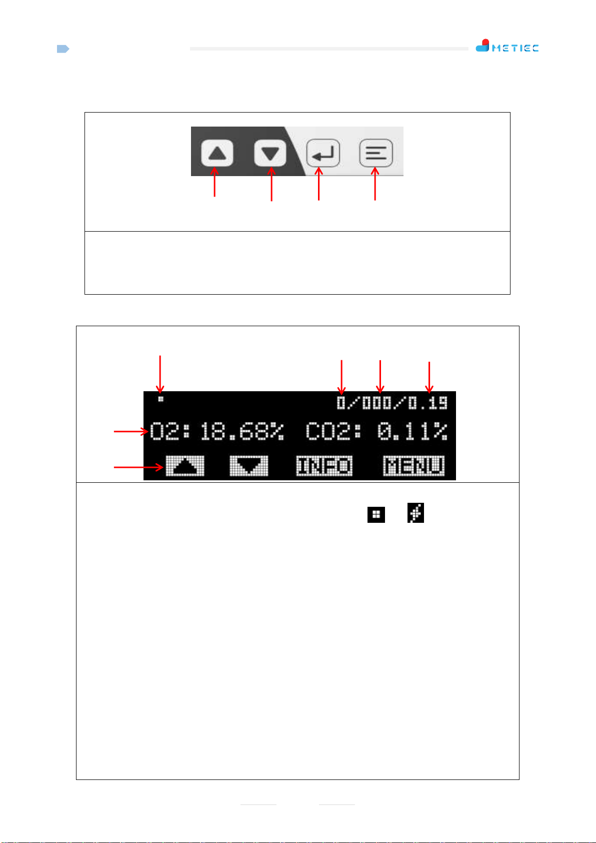
3.2.2 Main Interface Instructions
e) Breathing point of system operating state: It will flash when the system runs normally; it will be
normally on or off when the system breaks down; it will turn from " " to " " upon power failure,
prompting the power failure alarm;
f) Current flow value in the device mL/min (to test whether there is gas leakage inside the device): It is
generally displayed as "0" when there is no gas intake, indicating that the equipment is normal;
g) Pressure value input externally and processed by the pressure reducing valve (to test whether the gas
source has low pressure);
h) Current CO2concentration in the equipment (to detect whether there is gas leakage in the equipment):
When the value exceeds 0.5%, an alarm will be triggered;
i) Current concentrations of O2and CO2in the gas in the external gas pipe monitored by the equipment;
j) Function prompt icon of operation button: The button function will be different with the different
interfaces on the display.
Function Description of Buttons on the Current Interface:
UP key: No function (disabled);
DOWN key: No function (disabled);
OK key: Press it to enter "System information interface";
Menu key: Press it to enter "Parameter setting interface";
a)
b)
c)
d)
e)
f)
g)
h)
i
)
j
)

B1-MT300MIX
9
Main Interface and Operation Instructions During Intake
UP key: No function (disabled)
DOWN key: No function (disabled)
OK key: No function (disabled)
Menu key: No function (disabled)
Main Interface and Operation Instructions During Sampling after Intake
UP key: No function (disabled)
DOWN key: No function (disabled)
OK key: No function (disabled)
Menu key: No function (disabled)
Note:
1. When the device is in the state of intake sampling, the control operation will be shielded;
3.2.3 Instructions of System Information Interface
Press the "INFO" button on the main interface to enter the "System information interface", as
shown in the picture below:
First row: Displays equipment model;
Second row: Displays equipment SN;
Third row and fourth row: Displays the equipment software/ hardware version.
Instructions for key functions:
After the user presses any key, the system will return to the "Main interface" automatically.
3.2.4 Instructions of Setting Interface
Press the "MENU" button on the main interface to enter the "Setting interface" which includes
three pages and can flip, as shown in the picture below:
B1-MT300MIX
10
Menu Function Description:
"1. SET O2": O2 concentration calibration function;
"2. SET CO2": CO2concentration calibration function;
"3. SET DATA FREQ": Setting function of data upload frequency;
"4. SET SAMPLE FREQ": Setting function of sampling frequency;
"5. SET VALVER TIME": Setting function of intake time of single sampling;
"6.SET FLOW": Flow sensor calibration function;
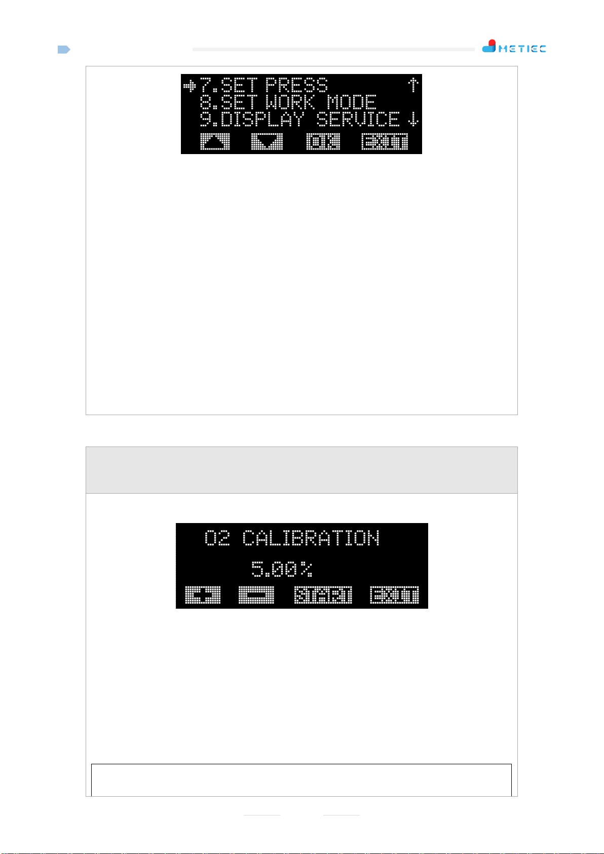
"7.SET PRESS": Calibration function of pressure sensor in rear of internal pressure reducing valve;
"8. SET WORK MODE": Work mode setting function of equipment;
"9. DISPLAY SERVICE": Real-time data display function.
Operation Instructions of Buttons:
UP key: Press this key to move to the previous option;
DOWN key: Press this key to move to the next option;
"OK": Confirm the selection;
"EXIT": The system exits and returns to the main screen (or the system automatically returns to the
main screen after 30 seconds) when the button is pressed;
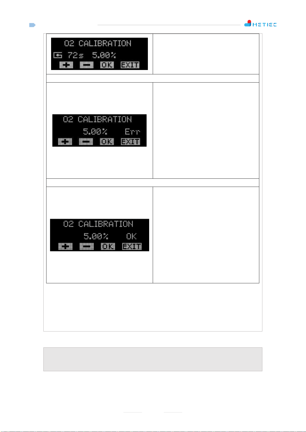
3.2.5 "1.SET O2"
Select "1.SET O2" on the setting interface, and then press the "OK" button to enter the O2
concentration calibration setting interface, as shown in the picture below:
O2Concentration Calibration Interface:
Operation Instructions of Buttons:
"+" key: Press this button to add the value by 0.1%and press and hold this button to add the value by
0.1% continuously;
"-" key: Press this button to reduce the value by 0.1% and press and hold this button to reduce the
value by 0.1% continuously;
"START" key : Press this button to start the intake calibration;
"EXIT" key: The system exits and returns to the main screen (or the system automatically returns to
the main screen after 30 seconds) when the button is pressed; press and hold this button for more
than 5 seconds to enter 21% (air calibration) concentration calibration interface;
Interface and Operation Instructions When Starting to Intake (Intake for 72 seconds by
default)
B1-MT300MIX
11
UP key: No function
DOWN key: No function
OK key: No function
Menu key: The system returns to the setting
interface when this key is pressed
Interface and Operation Instructions Upon O2Concentration Calibration Failure
UP key: Press this button to add the value by
0.1% and press and hold this button to add the
value by 0.1% continuously
DOWN key: Press this button to reduce the
value by 0.1% and press and hold this button to
reduce the value by 0.1% continuously
OK key: The system does not save the
calibration value and directly returns to the
setting interface when this key is pressed
Menu key: The system does not save the
calibration value and directly returns to the
setting interface when this key is pressed
Interface and Operation Instructions Upon Successful O2Concentration Calibration
UP key: Press this button to add the value by
0.1% and press and hold this button to add the
value by 0.1% continuously
DOWN key: Press this button to reduce the
value by 0.1% and press and hold this button to
reduce the value by 0.1% continuously
OK key: The system saves the calibration
value and returns to the setting interface when
this key is pressed
Menu key: The system does not save the
calibration value and directly returns to the
setting interface when this key is pressed
Note:
1. O2concentration calibration setting range: From 0% to 21%;
2. Calibrate two points: 5% concentration and 21% concentration (air calibration);
3. 21% concentration has been calibrated before delivery and does not need to recalibrate. If
calibration is required, press and hold the Menu key for more than 5 seconds to enter the calibration
interface.
3.2.6 "2.SET CO2"
Select "2.SET CO2" on the setting interface, and then press the "OK" button to enter the CO2
concentration calibration setting interface, as shown in the picture below:

B1-MT300MIX
12
CO2Concentration Calibration Interface:
Operation Instructions of Buttons:
"+" key: Press this button to add the value by 0.1%and press and hold this button to add the value by
0.1% continuously;
"-" key: Press this button to reduce the value by 0.1% and press and hold this button to reduce the
value by 0.1% continuously;
"START" key : Press this button to start the intake calibration;
"EXIT": The system exits and returns to the main screen (or the system automatically returns to the
main screen after 30 seconds) when the button is pressed;
Interface and Operation Instructions When Starting to Intake (Intake for 72 seconds by
default)
UP key: No function
DOWN key: No function
OK key: No function
Menu key: The system returns to the setting
interface when this key is pressed
Interface and Operation Instructions Upon CO2Concentration Calibration Failure
UP key: Press this button to add the value by
0.1% and press and hold this button to add the
value by 0.1% continuously
DOWN key: Press this button to reduce the
value by 0.1% and press and hold this button to
reduce the value by 0.1% continuously
OK key: The system does not save the
calibration value and directly returns to the
setting interface when this key is pressed
Menu key: The system does not save the
calibration value and directly returns to the
setting interface when this key is pressed
Interface and Operation Instructions Upon Successful CO2Concentration Calibration
UP key: Press this button to add the value by
0.1% and press and hold this button to add the
value by 0.1% continuously
DOWN key: Press this button to reduce the
value by 0.1% and press and hold this button to
reduce the value by 0.1% continuously
OK key: The system saves the calibration
value and returns to the setting interface when
this key is pressed
B1-MT300MIX
13
Menu key: The system does not save the
calibration value and directly returns to the
setting interface when this key is pressed
Note: CO2concentration calibration setting range: From 0% to 10%.
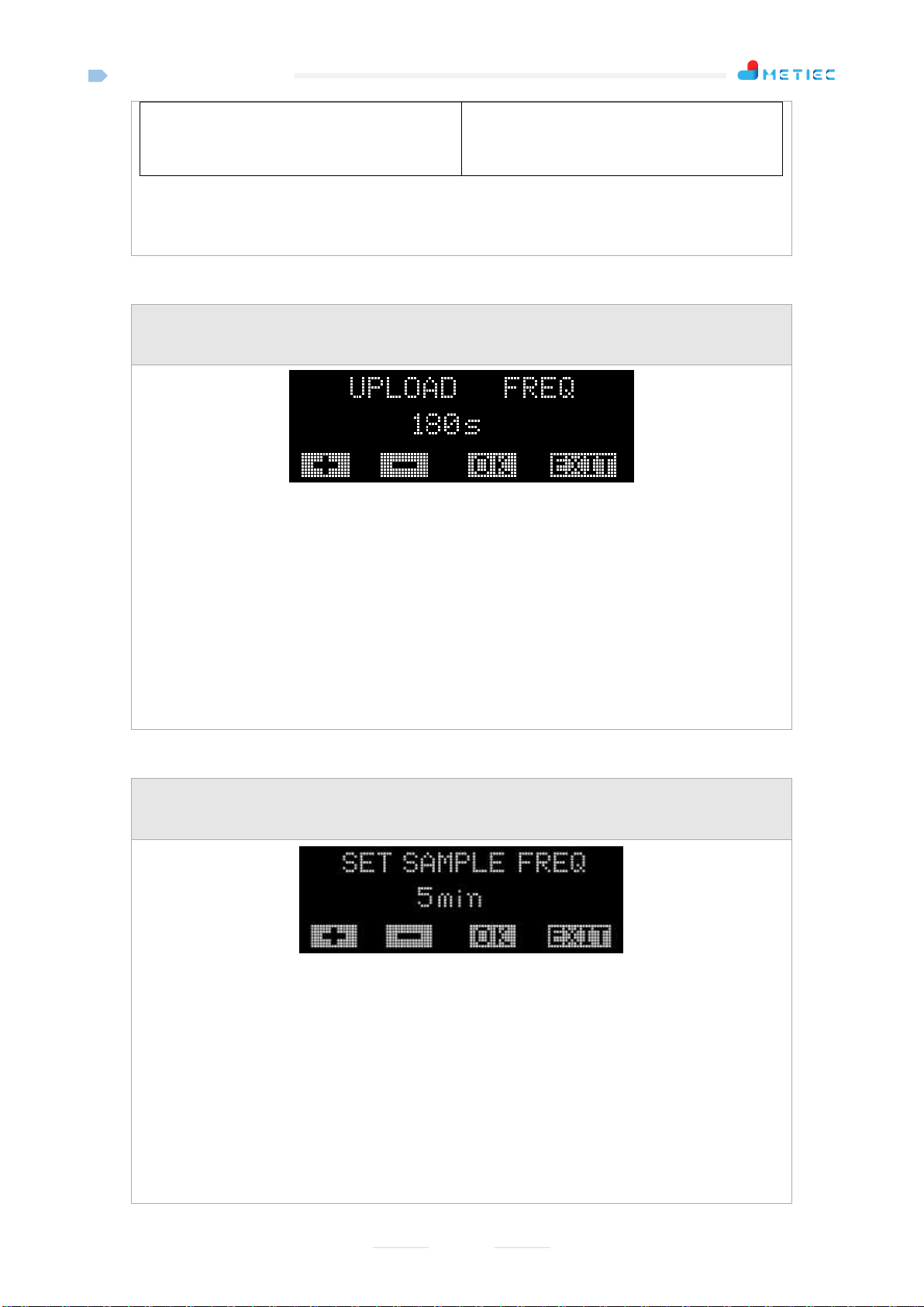
3.2.7 "3. SET DATA FREQ"
Select "3. SET DATA FREQ" on the setting interface, and then press the "OK" button to enter the
data upload frequency setting interface, as shown in the picture below:
Operation Instructions of Buttons:
"+" key: Press this button to add the value by 1 and press and hold this button to add the value by 1
continuously (in the range from 1~3600 seconds);
"-" key: Press this button to reduce the value by 1 and press and hold this button to reduce the value
by 1 continuously (in the range from 1~3600 seconds);
"OK" key: The system saves the parameter and returns to the main interface when this key is
pressed;
"EXIT" key: The system does save the parameter and directly returns to the main screen (or the
system automatically returns to the main screen after 30 seconds) when the button is pressed;
Note: The upload frequency is 180 seconds by default.
3.2.8 "4.SET SAMPLE FREQ"
Select "4.SET SAMPLE FREQ" on the setting interface, and then press the "OK" button to enter
the sampling frequency setting interface, as shown in the picture below:
Operation Instructions of Buttons:
"+" key: Press this button to add the value by 1 and press and hold this button to add the value by 1
continuously (in the range from 5~1440 seconds);
"-" key: Press this button to reduce the value by 1 and press and hold this button to reduce the value
by 1 continuously (in the range from 5~1440 seconds);
"OK" key: The system saves the parameter and returns to the main interface when this key is
pressed;
"EXIT" key: The system does save the parameter and directly returns to the main screen (or the
system automatically returns to the main screen after 30 seconds) when the button is pressed;
Note: The sampling frequency is 55 seconds by default.
B1-MT300MIX
14
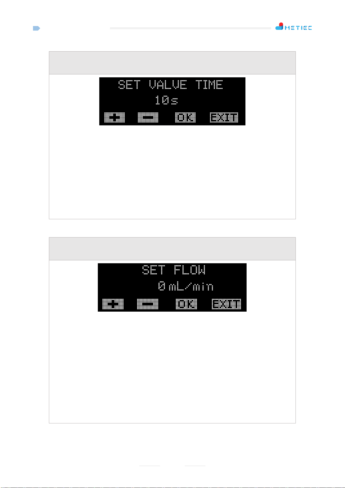
3.2.9 "5. SET VALVE TIME"
Select "5. SET VALVE TIME" on the setting interface, and then press the "OK" button to enter the
intake time setting interface for single sampling, as shown in the picture below:
Operation Instructions of Buttons:
"+" key: Press this button to add the value by 1 and press and hold this button to add the value by 1
continuously (in the range from 1~3600 seconds);
"-" key: Press this button to reduce the value by 1 and press and hold this button to reduce the value
by 1 continuously (in the range from 1~3600 seconds);
"OK" key: The system saves the parameter and returns to the main interface when this key is
pressed;
"EXIT" key: The system does save the parameter and directly returns to the main screen (or the
system automatically returns to the main screen after 30 seconds) when the button is pressed;
Note: The intake time is 10 seconds by default.
3.2.10"6.SET FLOW"
Select "6.SET FLOW" on the setting interface, and then press the "OK" button to enter the flow
sensor calibration interface, as shown in the picture below:
Operation Instructions of Buttons:
"+" key: Press this button to add the value by 1 and press and hold this button to add the value by 1
continuously (in the range from 1~1000 mL/min);
"-" key: Press this button to reduce the value by 1 and press and hold this button to reduce the value
by 1 continuously (in the range from 1~1000 mL/min);
"OK" key: The system saves the parameter and returns to the main interface when this key is
pressed;
"EXIT" key: The system does save the parameter and directly returns to the main screen (or the
system automatically returns to the main screen after 30 seconds) when the button is pressed;
Note: The flow sensor is used to detect leakage of the device. The factory has calibrated the zero, so
it is does not need to be calibrated by default; if the calibration is required, plug the gas inlet and
outlet and then calibrate the zero.
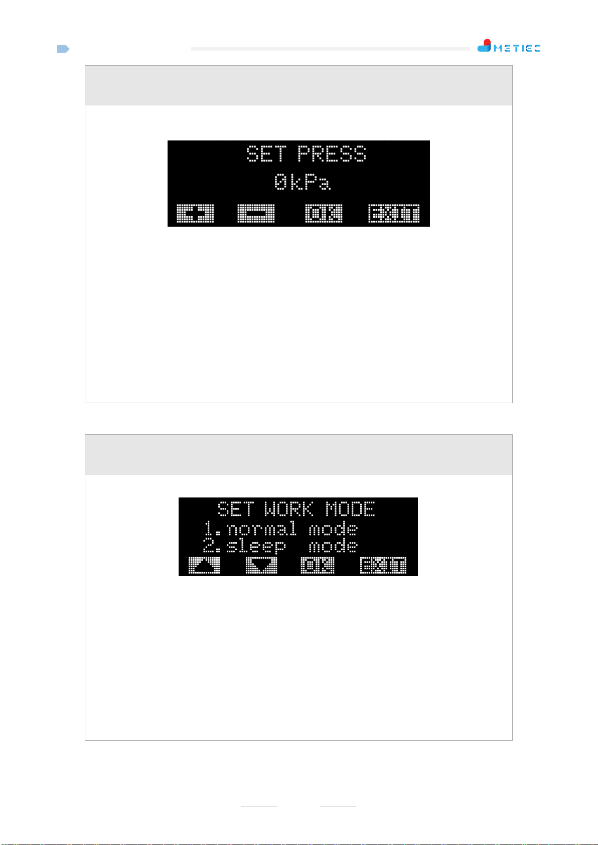
3.2.11"7.SET PRESS"
B1-MT300MIX
15
Select "7.SET PRESS" on the setting interface, and then press the "OK" button to enter the work
mode setting interface of the equipment, as shown in the picture below:
Operation Instructions of Buttons:
"+" key: Press this button to add the value by 1 and press and hold this button to add the value by 1
continuously (in the range from 1~200 kPa);
"-" key: Press this button to reduce the value by 1 and press and hold this button to reduce the value
by 1 continuously (in the range from 1~200 kPa);
"OK" key: The system returns to the main interface when this key is pressed;
"EXIT" key: The system does save the parameter and directly returns to the main screen (or the
system automatically returns to the main screen after 30 seconds) when the button is pressed;
Note: The pressure sensor is used to test whether the input pressure is too low. The factory has
calibrated the zero, so it is does not need to be calibrated by default; if the calibration is required, do
not input the gas into the pipeline but directly calibrate the zero under the atmospheric pressure.
3.2.12"8.SET WORK MODE"
Select "8.SETWORK MODE" on the setting interface, and then press the "OK"button to enter the
work mode setting interface of the equipment, as shown in the picture below:
Operation Instructions of Buttons:
"+" key: Press this key to switch over to the previous option;
"-" key: Press this key to switch over to the next option;
"OK" key: The system saves the parameter and returns to the main interface when this key is
pressed;
"EXIT" key: The system does save the parameter and directly returns to the main screen (or the
system automatically returns to the main screen after 30 seconds) when the button is pressed;
Note: The default working mode is "Normal Mode". "Sleep Mode" is generally applicable to
MT300MIX with battery function: In this mode, all detection functions are disabled and the device
enters the sleep state.
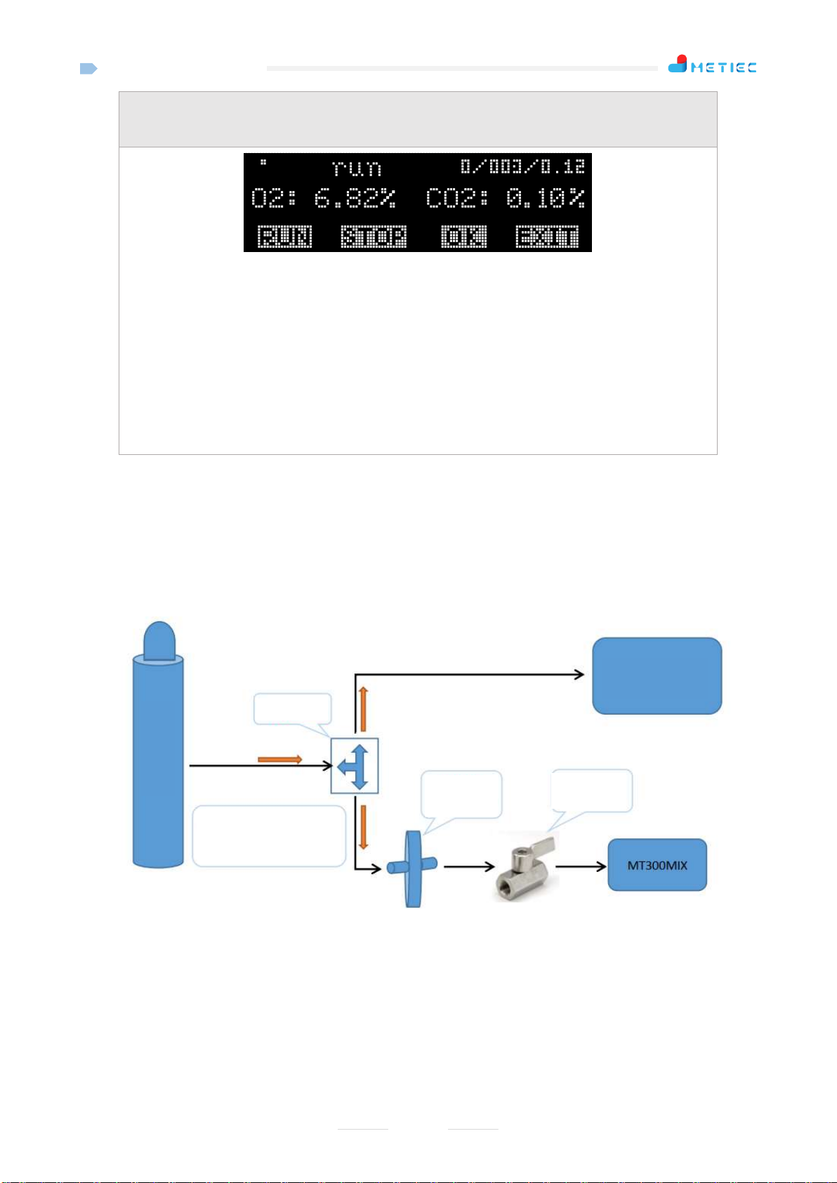
3.2.13"9. DISPLAY SERVICE"
B1-MT300MIX
16
Select "9. DISPLAY SERVICE" on the setting interface, and then press the "OK" button to enter
the real-time display interface of sampled data, as shown in the picture below:
Operation Instructions of Buttons:
"RUN" key: Used to update the concentration data of O2and CO2in real time;
"STOP" key: Used to pause update the concentration data of O2and CO2in real time;
"OK" key: The system returns to the main interface when this key is pressed;
"EXIT" key: The system returns to the main screen (or the system automatically returns to the main
screen after 5 minutes) when the button is pressed;
Note: This function can view the current sampled data in real time and be convenient for engineers
to debug the device. The sampled data on the main interface will be updated only when the intake is
sampled, and will be automatically locked until the next sampling.
4Installation Instructions
4.1 Installation Method 1
Connect the pre-mixing gas pipe to MT300MIX through a gas tee;
Gas tee
Manual
ball valve
HEPAgas
filter
Pre-mix gas
COOK
incubator
Note: The gas pipe joint
shall be fastened with the
mini M-type hose clamp.
B1-MT300MIX
17
Note: 1) In this installation mode, a disc filter should be added at the front end of the gas intake of MT300MIX to
prevent impurities from entering the equipment;
2) Hoops shall be installed at hose joints and tightened;
3) Pay attention to the pressure range of MT300MIX: 0.08MPA-0.2MPa;
4) Note that the total length of the pipe from tee to MT300MIX should not exceed 2 meters.
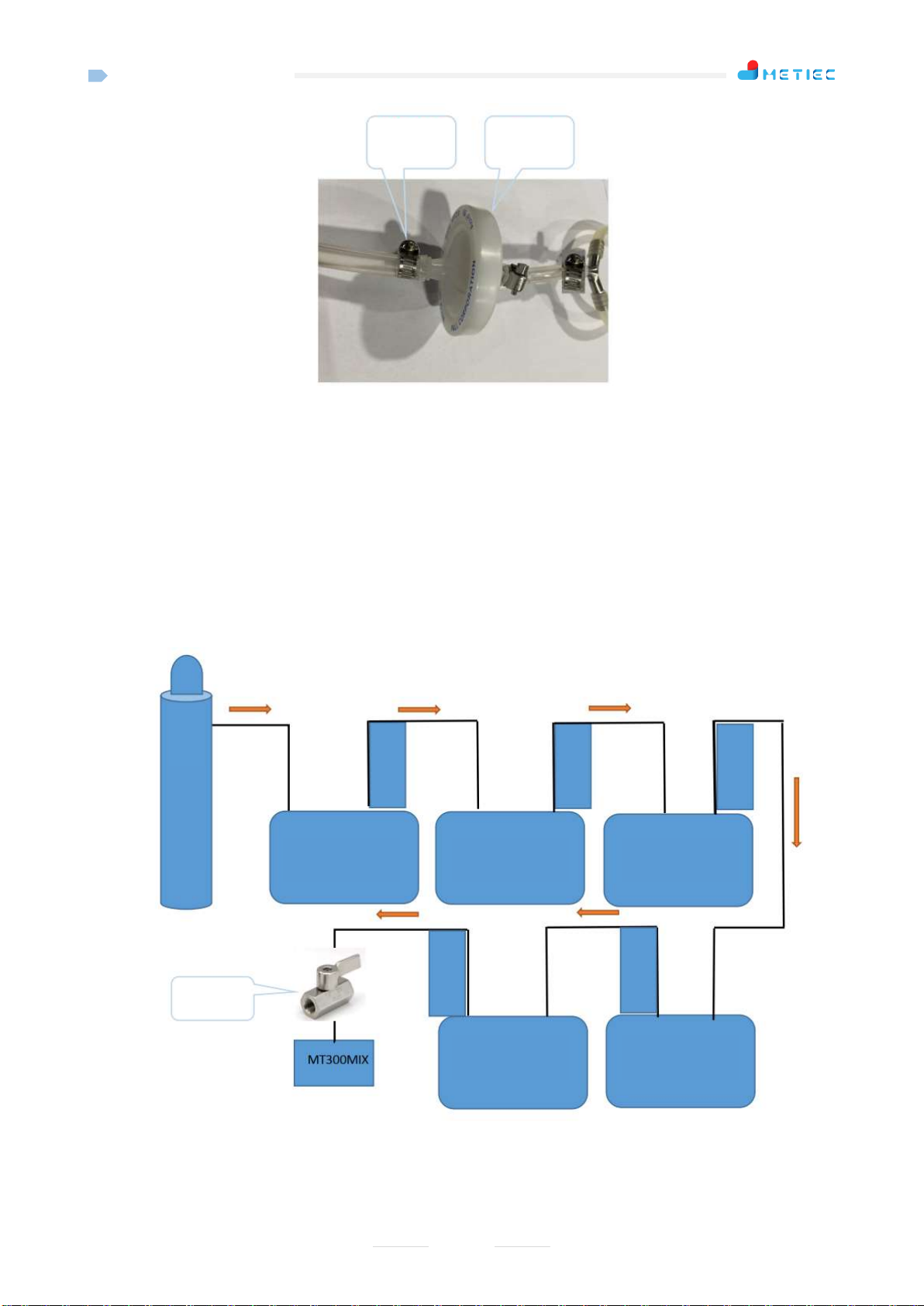
4.2 Installation Method 2
Connect MT300MIX to the final end of the pre-mixing gas pipe through the coupler of the
corresponding incubator;
Note:
1) Hoops shall be installed at hose joints and tightened;
2) Pay attention to the pressure range of MT300MIX: 0.08MPA-0.2MPa;
Manual
ball valve
Pre-mix gas
COOK
incubator
COOK
incubator
COOK
incubator
COOK
incubator
COOK
incubator
Union-assembly
HEPAgas
filter
Mini M-type
hose clamp
Union-assembly
Union-assembly
Union-assembly
Union-assembly

B1-MT300MIX
18
3) Note that the total length of the pipe from the last incubator to MT300MIX should not exceed 2 meters.
5Precautions
When MT300MIX is installed and used for the first time, because there is air inside the device, the air
cannot be guaranteed to be emptied at one time, therefore, the concentrations tested first few times after
the installation of the device will be inaccurate;
The wireless transmission distance of MT300MIX is limited and should generally not exceed 3 rooms. If
the walls of the rooms are made of metal materials, it is better to install a MT500 or MT1100 receiver in
each room;
MT300MIX is not waterproof, so the equipment shall not directly contact with liquid water;
MT300MIX is equipped with polymeric battery and shall be not allowed to contact the high temperature
environment to prevent battery damage.
The total length of the pipe fromthe last gas outlet (tee or last incubator) to MT300MIX should not exceed
2 meters.
6FCC Warning
15.19 Labeling requirements.
This device complies with part 15 of the FCC Rules. Operation is subject to the following two conditions: (1)
This device may not cause harmful interference, and (2) this device must accept any interference received,
including interference that may cause undesired operation.
15.21 Information to user.
Any Changes or modifications not expressly approved by the party responsible for compliance could void the
user's authority to operate the equipment.
15.105 Information to the user.
Note: This equipment has been tested and found to comply with the limits for a Class B digital device,
pursuant to part 15 of the FCC Rules. These limits are designed to provide reasonable protection against
harmful interference in a residential installation. This equipment generates uses and can radiate radio
frequency energy and, if not installed and used in accordance with the instructions, may cause harmful
interference to radio communications. However, there is no guarantee that interference will not occur in a
particular installation. If this equipment does cause harmful interference to radio or television reception,

B1-MT300MIX
19
which can be determined by turning the equipment off and on, the user is encouraged to try to correct the
interference by one or more of the following measures:
-Reorient or relocate the receiving antenna.
-Increase the separation between the equipment and receiver.
-Connect the equipment into an outlet on a circuit different from that to which the receiver is connected.
-Consult the dealer or an experienced radio/TV technician for help.
Table of contents
Popular Measuring Instrument manuals by other brands


Keysight
Keysight N2780B user guide

WATANABE ELECTRIC INDUSTRY
WATANABE ELECTRIC INDUSTRY A2200 Series Operation manual

Michell Instruments
Michell Instruments Pura user manual

PCE Instruments
PCE Instruments PCE-PFG Series user manual

Hach
Hach IntelliCAL ISENH3181 Series user manual

CyberVisuell
CyberVisuell LDW-6093K Operation manual

Tera
Tera TOM 600 ME manual

National Instruments
National Instruments NI Vision PCI-1409 user manual

Critical Environment Technologies
Critical Environment Technologies YES IMS Operation manual

Larson Davis
Larson Davis Spartan 730 Reference manual

Aichi
Aichi SD Series instruction manual

Fortis
Fortis 4063726007728 manual