Metkon MOBIPREP Administrator Guide

1
metkon.com
OPERATION & INSTRUCTION MANUAL
PORTABLE GRINDING/POLISHING & ELECTROLYTIC ETCHING

2
EC Declaration of Conformity
Manufacturer : Metkon Instruments Inc.
Address : Demirtas Dumlupinar Organize Sanayi Bolgesi
Ali Osman Sonmez Cd. No: 14 Bursa / TURKEY
Model No : MOBIPREP
Herewith declares that;
Portable Grinding/Polishing & Electrolytic Etching Machine
Confirms that it complies with the rules, in particular the protection requirements, which in the European Community Directive
on the approximation of the laws relating to electromagnetic compatibility (89/336/EEC), the Directive amending the CE marking
(93/68/EEC) and the Act are set out on the electromagnetic compatibility of equipment as of 18.09.1998.
This declaration applies to all identical copies of the product.
To assess the product with regard to electromagnetic compatibility, the following relevant harmonized European standards have
been applied, the reference numbers of which have been published in the Official Journal of the European Communities.
......................................................................................................................................................................
Date: 2017

3
Index
DESCRIPTION ............................................................................................................................ 4
Design .....................................................................................................................................................................................4
Technical Data ........................................................................................................................................................................5
Warranty .................................................................................................................................................................................6
Safety Precautions ..................................................................................................................................................................6
INSTALLATION & SET UP........................................................................................................... 7
Unpacking & Checking Contents of Package ...........................................................................................................................7
Installation and Set-Up ...........................................................................................................................................................7
Electrical Installation .......................................................................................................................................................................... 7
OPERATION ............................................................................................................................... 8
Charging the Battery................................................................................................................. 8
Connection of the Attachments to the Brushless DC Motor ....................................................................................................8
Reduction Gear (Reducer) Connection................................................................................................................................................8
90° and 45° Angle Attachment Connection.........................................................................................................................................9
Changing the Grinding and Polishing Carriers on Angle Attachment ...................................................................................................9
Straight Quick Release Piece Connection (Optional) ........................................................................................................................... 9
Changing the Grinding and Polishing Carriers on Straight Quick Release Piece (Optional) ..................................................................9
Grinding and Polishing Operation.......................................................................................................................................... 10
Etching (Optional) ................................................................................................................................................................. 10
Recommended Electrolytes .............................................................................................................................................................. 10
Replica .................................................................................................................................................................................. 10
SERVICE AND MAINTENANCE .................................................................................................. 11
Maintenance ..........................................................................................................................................................................11
Troubleshooting.....................................................................................................................................................................11
ACCESSORIES AND CONSUMABLES.........................................................................................12
Accessories ........................................................................................................................................................................... 12
Consumables......................................................................................................................................................................... 12
TECHNICAL DOCUMENTATION ................................................................................................14
Customer Service .................................................................................................................................................................. 14

4
DESCRIPTION
Design
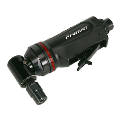
MOBIPREP is a battery powered portable Grinder / Polisher
and etcher designed for metallographic sample preparation in
field or in laboratory. MOBIPREP contains maintenance-free
batteries to work without stationary mains, consists of a
control unit and a precision hand-guided grinding-polishing
device with high performance micro motor. MOBIPREP’s
hand-guided device can be used with either 45° or 90° angle
or straight grinding-polishing pieces.
The switch for ON/OFF is on the hand-guide and provides a
click sensation with a confirmation tone from the control unit
when the switch is operated. All accessories are supplied with
a hardcase protection and carrying bag where you have
sufficient space to place your consumables. With the etching
pen, MOBIPREP can be used for electrolytic etching. Thus
working in field with alloyed steels is possible which can be
etched by weak electrolytes instead of strong acids.

5
Technical Data
Model
Order No
MOBIPREP
90 01
Voltages
36V or 100-240V / 50-60 Hz.
Speed
0 –25.000 rpm
2 LED Indicator
On / Low Battery
Operation Modes
E –Etching-1 (E1)
EP –Etching-2 or Polishing-1 (E2 or P1)
EPG –Etching-3 or Polishing-2 or Grinding-1 (E3 or P2 or G1)
PG –Polishing-2 or Grinding-2 (P2 or G2)
G3 –Grinding-3
G4 –Grinding-4
Disc Diameter
30 mm.
Reduction Gear
3.9:1
Dimensions, WxDxH
104 x 54 x 160 mm.
Weight
1 kg.

6
Warranty
The MOBIPREP is guaranteed against defective material or
workmanship defects for a period of 12 months from the date
of receipt by the customer or latest 18 months after the
shipping date. The warranty is not valid if inspection shows
evidence of misuse or unauthorized repair. Warranty covers
only replacement of defective materials. If this unit need to be
returned to our factory for service, please contact your
distributor for authorization and include the following details:
Serial Number of the unit, Invoice number and date. Transport
costs belong to the customer.
NOTE
The equipment is designed to be used with
METKON accessories and consumables. In case of
misuse of equipment, improper installation,
alteration, use of different source parts, improper
repair, METKON will accept NO responsibility for any
damages to the operator or the equipment. Disassembling of
any part should always be performed by a qualified
technician
NOTE
METKON Instruments Inc. can make any changes
without notice on the equipment, accessories,
consumables and miscellaneous products.
Consequently; visual or written information on
the instruction manuals, technical materials, catalogues,
website, product videos and other marketing materials may
show inconsistencies and may be different from the product.
Safety Precautions
Read the below instructions carefully before use.
The operator must be fully instructed in the use of the
equipment and its accessories and consumables,
according to the Instruction Manual.
The Material Safety Data Sheet for each Metkon
consumable can be reached from www.metkon.com
under E-Metkon section.
Check that the MOBIPREP is standing firmly on the
support.
Always place the MOBIPREP, micro motor, accessories
and the consumables in its carrier and protection bag.
Do not touch the electrical cable or other electrical parts
with wet hands!
When disconnecting MOBIPREP from power supply
always pull the plug out. Do not pull the cable!
Immediately disconnect MOBIPREP from power if water
or any other liquid penetrates the unit!
Do not put any metallic, flammable or other parts into
MOBIPREP or to its sockets!
Disconnect MOBIPREP from power after charging!
Do not connect any other devices than supplied to
MOBIPREP sockets!
Do not open the control unit or change any parts within
it!
Do not touch the micro motor while it is rotating.
When installing the accessories to the micro motor,
tighten the collet chuck correctly and recheck the collet
chuck before use. Do not over tighten the collet chuck.
This may cause damage to the spindle.
Do not apply excessive force. This may cause tool
slippage, tool damage, and injury to the operator, Ioss of
concentricity and precision.
Be sure to clean the collet chuck, the inside of the
spindle before replacing the grinding tool. If ground
particles or metal chips stick to the inside of spindle or
the collet chuck, damage to the collet chuck or spindle
can occur.
Stop working immediately when abnormal rotation or
unusual vibrations are observed. Immediately, check the
content of section “TROUBLESHOOTING”
When the motor and the attachment generate heat
because of continuous work, slow down the motor
speed, or stop the motor. Then, use it after the motor and
the attachment gets cold.
Always check if there are any damage on the equipment
and the accessories before and after operating.
Do not disassemble, modify or attempt to repair the
MOBIPREP. Additional damage will occur to the internal
components. Service must be performed by METKON or
an authorized service center.
In any case of disorder, please contact your supplier or
the manufacturer!

7
INSTALLATION & SET UP
Unpacking & Checking Contents of Package
Carefully unpack and check contents of the package. If any
components are missing or damaged, save the packing list
and materials and advise your distributor and the carrier of
the discrepancy.
Carefully unpack and check that the following items have
been received:
MOBIPREP
High Torque Brushless DC Motor
5 pcs. Grinding & Polishing Carrier
4 pcs. Storage box for consumables
90° Angle Attachment
Protection and Transport Case
WARNING
The MOBIPREP weights 1 kg. Please be sure that
the MOBIPREP is secured in order not to turn
upside down. Carefully remove outer packing
material. Refer to the packing documents for a
list of items supplied.
Installation and Set-Up
CAUTION
Follow approved procedures and take all
necessary preventive safety measures when
lifting and installing this equipment. Improper
lifting can result equipment damage.
You can see the dimensions and weight of MOBIPREP as
below:
Dimensions
W
D
H
104 mm
54 mm
160 mm
Weight
Approx. 1 kg
Electrical Installation
The MOBIPREP is a portable equipment for field work with a
rechargeable battery. Before making electrical connections
for recharging, check that the voltage and frequency stated
on the specification plate correspond to the local voltage and
frequency. Check that the values for single-phase voltage, is
compatible with the intended electrical supply before
installation.
ATTENTION
Connect the unit to the grounded mains
voltage.
WARNING
Electrical Shock Hazard. A qualified electrical
technician should perform all hard wiring and
electrical maintenance.
Disconnect the power supply before making any
electrical adjustments.
Make sure that the supply voltage and frequency is
correct. Check the values from the machine identification
plate located at the rear of the machine:
Voltage / Frequency
Operational
Power Range
Fuse Rating
230 V, 50/60 Hz. 1 ph.
200 - 250 V
5A (C Type)
115 V, 50/60 Hz. 1 ph.
100 - 125 V
5A (C Type)

8
OPERATION
MOBIPREP
CONTROL UNIT
1
Green LED Indicator - ON
2
Red LED Indicatior –Low Battery
3
Adjusting knob for Grinding/Polishing and Etching
•E –Etching-1 (E1)
•EP –Etching-2 or Polishing-1 (E2 or P1)
•EPG –Etching-3 or Polishing-2 or Grinding-1
(E3 or P2 or G1)
•PG –Polishing-2 or Grinding-2 (P2 or G2)
•G3 –Grinding-3
•G4 –Grinding-4
4
Socket for Hand Guided Brushless DC Motor and
Etching Pen
5
Charging Socket
Control Unit
HAND GUIDED BRUSHLESS DC MOTOR
6
Angle Piece 90°
(Alternatively Angle Piece 45° or Straight Piece)
7
Reduction Gear 4:1 (Increases rotation moment)
8
High Performance Micro Motor with click sensitive
ON-OFF-Switch
Charging the Battery
To charge the built-in batteries;
Connect the battery charger to the charging socket (#5).
The batteries of MOBIPREP are now being charged. When
the batteries are fully charged, the Battery Indicator Iights
green. If the batteries need charging the Battery Indicator
will Iight red.
WARNING
A fully charged set of batteries will self-
discharge in 4-6 months, and a complete
discharging may reduce the lifetime.
Therefore, the batteries should be charged at
regular intervals.
Connection of the Attachments to the
Brushless DC Motor
CAUTION
Make sure your hands and all interlocking
parts of the Attachments and motor are clean
before connecting the motor to the
Attachment. This is critical in preventing
contaminants from entering the motor or Attachment.
Reduction Gear (Reducer) Connection
Align the threads on the front end of the motor and the
rear end of the reducer, and turn the reducer clockwise.
If the drive shaft of the motor does not engage the drive
dog on the reducer, you may only turn it about 2 turns.
DO NOT FORCE.
Turn the reducer back a few threads, rotate the thread on
the front end of the reducer by hand to engage the drive
shaft and the drive dog, and screw them together with a
provided pin wrench (spanner).
Below photo shows the connection of the Reduction
Gear (Reducer).
Reduction Gear (Reducer) Connection
1
2
3
4
5
6
7
8

9
90° and 45° Angle Attachment Connection
45° angle attachment is supplied as an optional accessory.
Align the thread on the front end of the motor and the
rear end Angle Attachment, and turn the Angle
Attachment clockwise.
If the drive shaft of the motor does not engage properly
to the drive dog on the Attachment, it may only turn
aprroximately two threads before stopping. DO NOT
FORCE!
In case of unproper engagement loosen the Angle
Attachment from the motor, rotate the Angle Attachment
shaft by hand then re-try. The drive shaft and the drive
dog must be fully engaged.
When fully engaged, secure the motor and Angle
Attachment using the provided pin wrench.
Below photo shows the connection of the Angle
Attachment.
Angle Attachment Connection
Changing the Grinding and Polishing Carriers on Angle
Attachment
Attach the collet wrench provided onto the head of the
Attachment. Apply Iight pressure to the head of the collet
wrench. Place the wrench on the collet chuck.
Turn it slowly counterclockwise. The collet wrench will
engage within 90° of wrench rotation.
Keep turning the wrench until the rod on the angle
attachment can be removed.
When mounting the grinding & polishing carriers, rotate
the wrench clockwise to tighten the cutting tool firmly.
Below photo shows the changing of the grinding &
polishing carriers on Angle Attachment.
Changing Carriers
Straight Quick Release Piece Connection (Optional)
Align the threads on the front end of the motor and the
rear end attachment, and turn the attachment clockwise.
If the drive shaft of the motor does not engage the drive
dog on the attachment, you may only be able to turn it
about 2 turns. DO NOT FORCE!
In case of unproper engagement, turn the attachment
back a few threads, rotate the attachment by hand to
engage the drive shaft and the drive dog, and screw them
together with a provided wrench.
Below photo shows the connection of the Straight Quick
Release Piece.
Straight Quick Release Piece Connection
Changing the Grinding and Polishing Carriers on
Straight Quick Release Piece (Optional)
Turn the Iock spindle towards the arrow as shown on
below photo to release the rod and remove by hand.
Changing the Carriers
Mount the grinding & polishing carriers firmly and lock
the spindle to the “CLOSE” position.
If it is hard to remove the collet chuck, use the provided
wrench.
When putting high torque by cutting tools or when
turning toward closing the collet chuck, there is a case
where the collet chuck or cutting tools cannot be put off
by hand. If so, set the provided wrench to the collet
chuck; open the lock spindle (lever). Then, turn the
wrench counterclockwise to release the collet chuck or
the cutting tools (below photo).

10
Grinding and Polishing Operation
Connect the hand guided device to socket #4
Select the Grinding Mode (G) from the adjustment knob
#3 for grinding.
Place the SiC grinding paper ø30 mm (80-1200 grit)
Select the Polishing Mode (P1 or P2) from the adjustment
knob #3 for polishing. P1 for pre-polishing and P2 for fine
polishing.
Place the polishing cloth on the carrier as shown in
below photo.
Diamond pastes are applied to the cloth as abrasive
particles of a given grain size (9 μ–6 μ–3 μ–1 μ–0.25
μ).
Sufficient lubrication with diamond lubricant between
the sample surface and the polishing cloth is necessary. It
reduces friction and cools the specimen. The polishing
cloth should be moist, not wet.
The hand guided device can be switched ON and OFF
directly on the micro motor (green control button).
Light pressure is recommended during grinding and
polishing.
After grinding or polishing, between each step, the
prepared spot has to be cleaned with water or with
alcohol (ethanol).
Etching (Optional)
After grinding and polishing (instead of chemical etching),
electrolytic etching of the prepared spot may be used with
connecting the Etching Pen.
Connect the Etching Pen to Socket #4.
Clamp the anode (red wire) of the Etching Pen to the
sample or work piece by the clamp or the magnetic
anode supplied.
Select the Etching Mode (E1 or E2) from the adjustment
knob #3
Remove the closing cap and insert a cotton-wool
applicator into the Etching Pen.
Fill the Etching Pen with the relevant electrolyte
(depending on material) using the syringe by putting the
syringe into the filling hole on the side of the etching pen.
The cotton-wool applicator is soaked with the relevant
electrolyte.
Wipe the etching pen on the prepared spot until etching
is done. (The mirror-like polished surface becomes
darker).
After the etching process is finished, clean the area with
water or alcohol (ethanol) to stop the etching process.
Do not over etch when using the portable microscope.
For getting a replica for laboratory examination make
over etching.
When not in use the close the cap of the Etching Pen.
Etching
Recommended Electrolytes
Materials
Electrolyte
Etching
(Replacing Chemical
Etching with…)
Carbon steels
Special Salt
Solutions
e.g. 5% NaCl
solution
E2
(Nital)
Aluminum
Alloys
(10% NaCl solution)
Austenitic
stainless
steels
10% oxalic acid
E1
(V2A-steel
formulation)
High-alloyed
steels
Nital (3% HNO3 in
ethanol) + water
(50:50) or 3%
aqueous HNO3
E2
(concentrated acid
formulations)
(ferritic /
martensitic)
Replica
The material is cellulose acetate of a thickness 35 micron
(0.0014 inch) and it is soluble in acetone.
Cut a piece of the replica material from the sheet, which
is suitable to cover the area to be replicated.
Drop one or two drops of acetone on to the specimen
surface.
Place the replica film immediately on the surface
(allowing surface tension forces to pull it down; no
pressure is required).
The cellulose acetate film should be left to dry for about
10 minutes until it will splitted very easily from the
surface.
Remove the film from the surface and place between 2
cover glass slide for examination under microscope.

11
SERVICE AND MAINTENANCE
Maintenance
Clean the MOBIPREP with a soft, slightly dump cloth.
Clean the grinding & polishing carriers and the
accessories before attaching to the micro motor to
prevent dust and particule contamination.
Troubleshooting
ERROR
DESCRIPTION
ACTION
Overheating during rotation
Excessive force is applied during
operation
Lower the force applied.
Abnormal vibration or noise during
rotation
The grinding & polishing carrier is bent.
Replace the grinding & polishing
carrier
Cutting Tool Slippage
Collet chuck is not correctly
installed
Check and clean the collet chuck.
Reinstall the collet chuck and re-
tighten.
High Run Out
The grinding & polishing carrier is bent.
Replace the grinding & polishing
carrier
Collet chuck is worn
Replace the Collet chuck

12
ACCESSORIES AND CONSUMABLES
Accessories
Order No
Accessories for MOBIPREP
90 10
Etching-Pen for electrolytic etching
90 11
Angle piece 90 °, with 3-mm collet on
90 12
Angle piece 45 °, with 3-mm collet on
90 13
Straight quick release piece of, with 3-mm collet on
90 14
Grinding and polishing carriers (5 pieces)
90 15
Shoulder bag for Mobiprep, synthetic leather
Consumables
In-situ/Field metallography is widely used for microstructure analysis on large parts (samples) that cannot be easily carried or
where destructive preparation is permissible such as storage tanks, piping system, power plants, etc. In-situ Metallography
allows for quick on-site evaluation of a component. There are numerous advantages in using in-situ/field metallography.
Order No
CODE
Paper Grinding Discs, Self-Adhesive Back (1 Pack 250 Pcs.)
90 20
DEMPAX-P
SiC-grinding papers, self-adhesive, 250 pieces (• 30 mm), 80 Grit
90 21
DEMPAX-P
SiC-grinding papers, self-adhesive, 250 pieces (• 30 mm), 120 Grit
90 22
DEMPAX-P
SiC-grinding papers, self-adhesive, 250 pieces (• 30 mm), 320 Grit
90 23
DEMPAX-P
SiC-grinding papers, self-adhesive, 250 pieces (• 30 mm), 500 Grit
90 24
DEMPAX-P
SiC-grinding papers, self-adhesive, 250 pieces (• 30 mm), 800 Grit
90 25
DEMPAX-P
SiC-grinding papers, self-adhesive, 250 pieces (• 30 mm), 1200 Grit
Order No
CODE
Polishing Cloth Self-Adhesive (1 Pack 50 pcs.)
90 26
PORTO
Polishing Cloth (30 mm) for 0.25, 1, 3 microns (50 pcs.)
90 27
RADO
Polishing Cloth (30 mm) for 6, 9 microns (50 pcs.)

13
Order No
CODE
Diamond Pastes, Monocrystalline
39-301-M
DIAPAT-M
Diamond Paste, 0.25 µm, 10gr. syringe
39-311-M
DIAPAT-M
Diamond Paste, 1 µm, 10gr. syringe
39-321-M
DIAPAT-M
Diamond Paste, 3 µm, 10gr. syringe
39-331-M
DIAPAT-M
Diamond Paste, 6 µm, 10gr. syringe
39-341-M
DIAPAT-M
Diamond Paste, 9 µm, 10gr. syringe
Order No
CODE
Diamond Lubricant
39-502
DIAPAT
Diamond Lubricant, Water-based, 1 lt bottle
Order No
CODE
Replica Set & Etching Consumables
90 28
Cotton rolls (100 pcs) for electrolytic etching
90 40
REPLI
Replica foil 35 microns thick, to be used with acetone
90 41
Microscope slide glasses

14
TECHNICAL DOCUMENTATION
Customer Service
Our factory-trained assembly personal is at your disposal for customer service.
Please contact the following address:
Head Quarter
Metkon Instruments Inc.
Demirtas Dumlupinar Organize Sanayi Sitesi
Ali Osman Sonmez Cad. No: 14 Bursa/TURKEY
Tel: +90 (224) 261 1840
Fax: +90 (224) 261 1844
E-Mail: [email protected]
Web: www.metkon.com

15
This manual suits for next models
1
Table of contents
Other Metkon Grinder manuals

