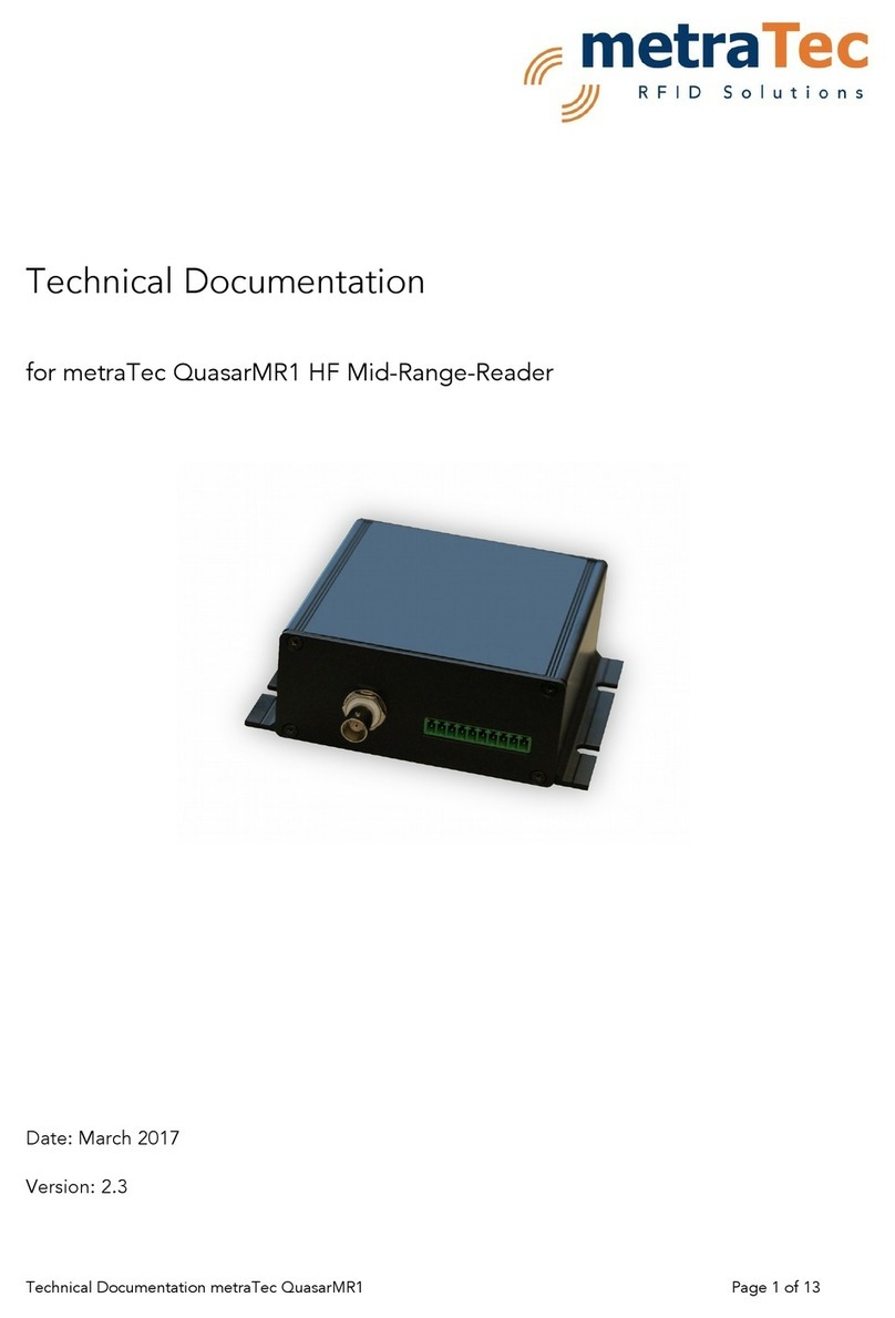
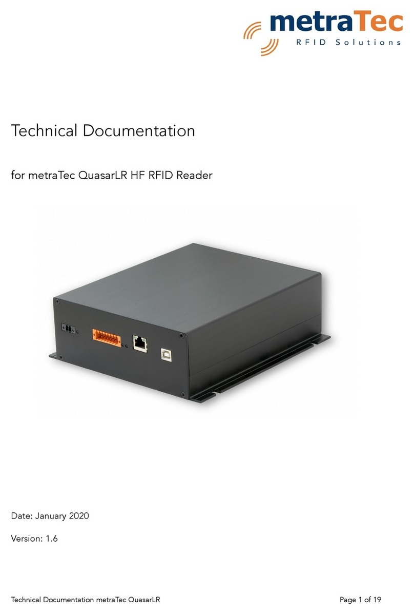
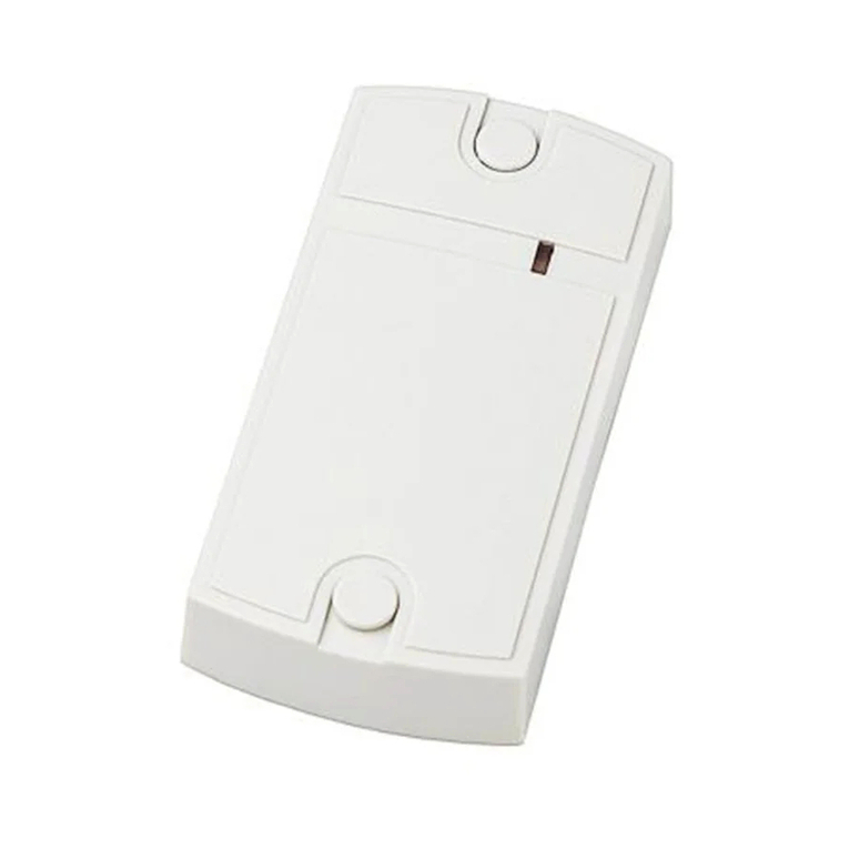
metraTec DMI15 Guide

Technical Documentation
for metraTec DMI15 IoT HF RFID Reader
Date: December 2020
Version: 1.0
Technical Documentation metraTec DMI15 age 1 of 18

Table of Contents
1 General Information / Security Advice................................................................................3
1.1 Notes on the use of this documentation.......................................................................3
1.2 Security Advice.............................................................................................................3
1.3 Export Restrictions........................................................................................................3
1.4 Further Documents.......................................................................................................3
2 roduct Description............................................................................................................4
2.1 Intended Use................................................................................................................4
2.2 Technical Specification.................................................................................................5
2.3 roduct Drawing...........................................................................................................6
2.4 Scope of Delivery.........................................................................................................7
2.5 Accessories...................................................................................................................7
3 ower Supply Electrical Specification..................................................................................8
4 Ethernet configuration......................................................................................................10
5 RFID Antenna....................................................................................................................11
6 Digital Input/Outputs........................................................................................................12
7 LEDs..................................................................................................................................15
8 Further Notes....................................................................................................................16
8.1 Environmental.............................................................................................................16
8.2 Declaration of Conformity..........................................................................................16
9 Version Control.................................................................................................................17
Technical Documentation metraTec DMI15 age 2 of 18

1 General Information / Security Advice
1.1 Notes on the use of this documentation
This user manual and integration guide uses different symbols to point out potentially
dangerous situations. The following signs and symbols are used throughout the document.
ATTENTION
Declares a potentially hazardous situation. If this is not avoided, the product
or something in its surrounding could be damaged.
NOTE
Declares notes for the user as well as other useful information, where no
harmful or dangerous situations can be expected.
1.2 Security Advice
The DMI15 IoT HF RFID Reader was not designed for use in dangerous environments. Using
this product in applications where a failure could directly results in severe injuries or death
(“high risk activities”) is not permitted. This includes but is not limited to applications in
nuclear facilities, flight control systems, life support systems or weapon systems. The
manufacturer denies the suitability of this device for such scenarios.
1.3 Export Restrictions
The DMI15 contains components that underlie US Export restrictions. It is therefore
forbidden to export the product to countries that are on the US trade embargo list. The
same applies to any countries that are on the EU embargo list.
1.4 Further Documents
While this documentation explains the electrical and mechanical characteristics of the
DMI15 RFID Reader, it might be useful to also read the metraTec rotocol Guide, which
explains the ASCII protocols used to control the reader in full detail.
We also offer general information about how to set up the connection of the reader to the
antenna for optimum system performance in our HF Antenna Integration Guide.
All further documents can be either found at the metraTec's product web page or are listed
at: http://www.metratec.com Support Downloads Documentation.
Technical Documentation metraTec DMI15 age 3 of 18

2 roduct Description
The DMI15 is an IoT HF RFID reader/writer for demanding industrial applications, where
high reading reliability, speed and extensive special tag features are needed.
The DMI15 communicates via LAN and can be powered over Ethernet ( oE) making the
integration in IoT systems real plug and play, especially when used in conjunction with the
metraTec IoT Engine software.
Highlights include a reading rate of up to 100 tag-IDs/sec and reading and writing data on
tags without needing to address them individually. This allows applications directly at
conveyor belts, in production machinery and in electric control cabinets. The communication
protocol can be used from a normal C with a full operating system, with embedded
systems as well as with a LC.
2.1 Intended Use
RFID Reader/Writer for wireless communication with passive RFID transponders according
to ISO 15693.
Technical Documentation metraTec DMI15 age 4 of 18

2.2 Technical Specification
Operating Voltage 24 V DC in
oE class 0 (13W max., isolated)
Digital Inputs/Outputs optically isolated 24V DC Inputs (2x)
24 V DC Outputs (4x)
24 V DC Out (1x)
Operating Frequency 13.56 MHz
System Impedance 50 Ohm
RF Output 250 mW
Max. ower Consumption 5W (RF ON)
Operating Temperature -40°C to +85°C
Dimensions 120 x 90 x 50 mm
rotection I 40
Conformity CE, ETSI EN 300 330
Technical Documentation metraTec DMI15 age 5 of 18

2.3 roduct Drawing
The DMI15 features 4 mounting holes on a 99 x 34 m grid. The housing may be used as
drilling template using a deep hole marker.
Technical Documentation metraTec DMI15 age 6 of 18

2.4 Scope of Delivery
The DMI15 RFID Reader comes with the following parts:
•DMI15 RFID Reader
•Documentation, Drivers and Demo Software are available via download from
metraTec's website (http://www.metratec.com Support Downloads)
2.5 Accessories
The following accessories and modules are available to extend and evaluate the
functionality of the DMI15 RFID Reader:
•24V 1A power supply
•Transponders
Technical Documentation metraTec DMI15 age 7 of 18

3 ower Supply Electrical Specification
The preferred method of powering the DMI15 is using oE. Simply connect the DMI15 to a
oE enabled Ethernet switch using a standard Ethernet cable. The DMI15 will be detected
as a oE class 0 device by the ethernet switch. The switch will deliver up to 13W available
for the DMI15 itself shared with devices connected to the 24V outputs as well as the 24V DC
out of the DMI15. Exceeding the 13W overall power rating will result in shut down of the
power supply by the ethernet switch.
Alternatively the DMI15 can be powered using the 24V DC input which are available at the
IO connector at the front of the device (X2). If you do not use a power supply supplied by
metraTec, please make sure that your own SU provides a supply voltage of high quality.
The DMI15 uses internal diode power OR-ing at the 24V level. The oE power input is
converted to 24V and compared to the voltage at the 24V DC input. The higher voltage will
be used to supply the DMI as well as the IOs.
Fig. 1: Connector description of DMI15
Connector Description
X2.1 GND
X2.2 24V DC
Tab. 1: Pinout of DC Input at IO Connector X2
Technical Documentation metraTec DMI15 age 8 of 18

Operating Voltage 24 V DC
ower Consumption, RF on 200 mA
ower Consumption, RF off 80 mA
ower Consumption, Sleep 20 mA
Tab. 2: Typica Current Consumption at 24V DC
Technical Documentation metraTec DMI15 age 9 of 18

4 Ethernet configuration
The DMI15 offers a 100 MBit Ethernet connection as communication interface via a RJ-45
jack.
The DMI15 incorporates a metraTec TC to UART Converter (TUC) for ethernet
communication.
The default I setting is static 192.168.2.239.
The interface configuration is available at this address using a web browser (port 80).
The serial ASCII data stream is available at port 10001 using a terminal program. We
strongly recommend metraTerm available as free download on our website.
For more details and options see the metraTec TUC user guide.
Technical Documentation metraTec DMI15 age 10 of 18

5 RFID Antenna
To send and receive data to and from passive RFID tags the DMI15 includes a HF RFID
antenna (13.56 MHz, 50 Ohm) The antenna is located centered at the front of the housing.
The antenna center is indicated by the top print.
The transponder should be aligned parallel to the top cover of the box.
The reading range can be up to 10cm for credit card size transponders.
The reading range will depend to a great extent on the size, power consumption and quality
of the transponder and needs to be evaluated for each application individually. Make sure
to have enough margin to allow for deviations in transponder read range.
Make sure there is enough distance to other HF RFID readers and other devices using the
13.56 MHz ISM frequency band.
Technical Documentation metraTec DMI15 age 11 of 18

6 Digital Input/Outputs
The DMI15 has 2 digital inputs and 4 digital outputs which can be read or set via the reader.
The input pins are optically isolated 24 V DC inputs as is common in automation
technology. Up to 10 mA are needed to set the input to "high".
The output pins are 24 V high side switch DC outputs with a maximum current of 250 mA
per pin. These can be used to directly power e.g. signal towers. In total a maximum output
current of 1000 mA for all pins is allowed when 24V DC power is supplied at the IO
connector. Otherwise the 13W oE power limit will apply. Outputs are equipped with
internal overcurrent and overtemperature protection.
arameter min typ max
Supply voltage Vcc/ V 12 24 30
Vin High / V 12 24 30
Vin Low / V -0.7 0 3
Vout High / V Vcc-2 Vcc-0,5 Vcc
Vout Low / V 0 0,5 3V
Iout High / mA 200 250 270
Iin High / mA 4 10 25
Technical Documentation metraTec DMI15 age 12 of 18

The pins X2.1 and X2.2 are used as an alternative power supply input. The applied voltage
is 24 V DC. ins X2.15 and X2.16 are directly connected to X2.1 and X2.2 respectively.
These can be used as power supply outputs to supply e.g. sensors, etc. The power of these
pins is limited by the power of the power supply used or the oE power limit.
Technical Documentation metraTec DMI15 age 13 of 18
Fig. 2: Connector description of DMI15

Connector Name Description
X2.1 GND power input, directly connected to X2.15
X2.2 24V DC power input, directly connected to X2.16
X2.3 Out 1 - Return for Out1 +, internally connected to GND
X2.4 Out 1 + 24V out, internal high side switch, 250mA max.
X2.5 Out 2 - Return for Out2 +, internally connected to GND
X2.6 Out 2 + 24V out, internal high side switch, 250mA max.
X2.7 Out 3 - Return for Out3 +, internally connected to GND
X2.8 Out 3 + 24V out, internal high side switch, 250mA max.
X2.9 Out 4 - Return for Out4 +, internally connected to GND
X2.10 Out 4 + 24V out, internal high side switch, 250mA max.
X2.11 In 1 - Optically isolated input 1, negative
X2.12 In 1 + Optically isolated input 1, positive
X2.13 In 2 - Optically isolated input 1, negative
X2.14 In 2 + Optically isolated input 1, positive
X2.15 GND power output, directly connected to X2.1
X2.16 24 V DC power output, directly connected to X2.2
Tab. 3: Pin Description for digita IOs.
Technical Documentation metraTec DMI15 age 14 of 18

7 LEDs
The DMI15 features 5 LEDs.
The three top LEDs indicate the status of the RFID engine.
Two more LEDs on the RJ45 socket show the Ethernet status.
Name Number Color Function
ower 1 green Indicates that a valid power supply is
connected to the DMI15
RF_On 2 amber Indicates that the RF field is turned on
Tag_Detect 3 blue Indicates that a transponder inventory,
read or write operation was carried out
successfully
Link 4 amber Left LED on RJ-45 Ethernet connector, is
permanently on when a link is
established
Data 5 green right LED on RJ-45 Ethernet connector,
flashes on send and receive of data
packets
Technical Documentation metraTec DMI15 age 15 of 18

8 Further Notes
8.1 Environmental
Electronic devices like the DMI15 are covered by the (German) ElektroG (electronic waste
law) as well as the European WEEE directive and as such may not be disposed of by way of
the normal household trash. Instead they have to be recycled properly. For you as our
customer this is no additional burden, however, as you can send the device back to us for
proper recycling. We assure you that the devices received back will be recycled properly
and in an environmentally friendly way. Our WEEE Registration ID is DE 56060482.
When selecting electronic components we additionally made sure that all components are
free of heavy metals and other harmful substances as required by the RoHS and REACH
Directives for many industries. Hence, our products are produced in the most
environmentally friendly way possible.
8.2 Declaration of Conformity
The DMI15 complies with all directives and regulations applicable in the European Union for
this kind of device. This especially includes all laws regarding use of spectrum and EMC. The
product therefore bears the CE sign, as required by Directive 1999/5/EC (Radio &
Telecommunication Terminal Equipment Directive).
The product is currently not registered for use in the US or Canada. However, metraTec is
registered as a manufacturer of electronics at the FCC and IC. A certification of this product
is therefore possible, if required. lease ask us or your system integrator for further
information.
Technical Documentation metraTec DMI15 age 16 of 18

9 Version Control
Version Change by Date
1.0 created TM 22.12.2020
Technical Documentation metraTec DMI15 age 17 of 18

Contact
metraTec GmbH
Niels-Bohr-Str. 5
39106 Magdeburg, Germany
Tel.: +49 (0)391 251906-00
Fax: +49 (0)391 251906-01
Email: [email protected]
Web: http://www.metratec.com
Copyright
© 2020 metraTec GmbH
Reprint or reproduction of this documentation for other than internal purposes is only allowed with
written permission by metraTec GmbH.
All trademarks are the property of their respective owners.
All right reserved.
We are constantly improving our products. Changes in function, form, features can happen without
prior notice.
Technical Documentation metraTec DMI15 age 18 of 18
Table of contents
Other metraTec RFID System manuals

