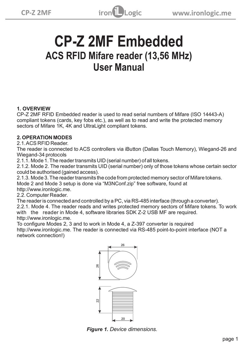
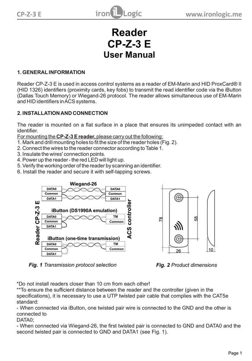
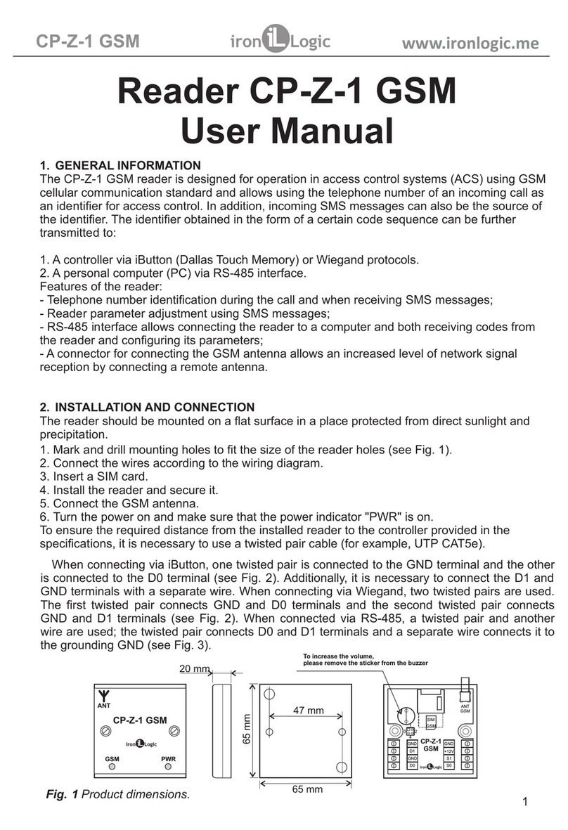
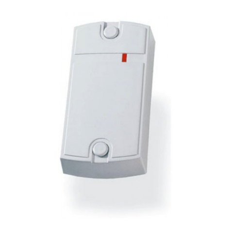
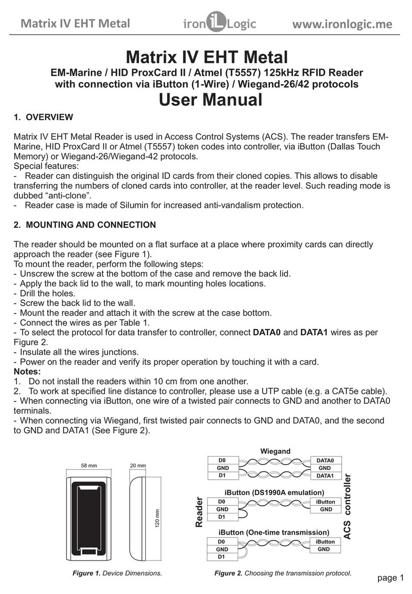
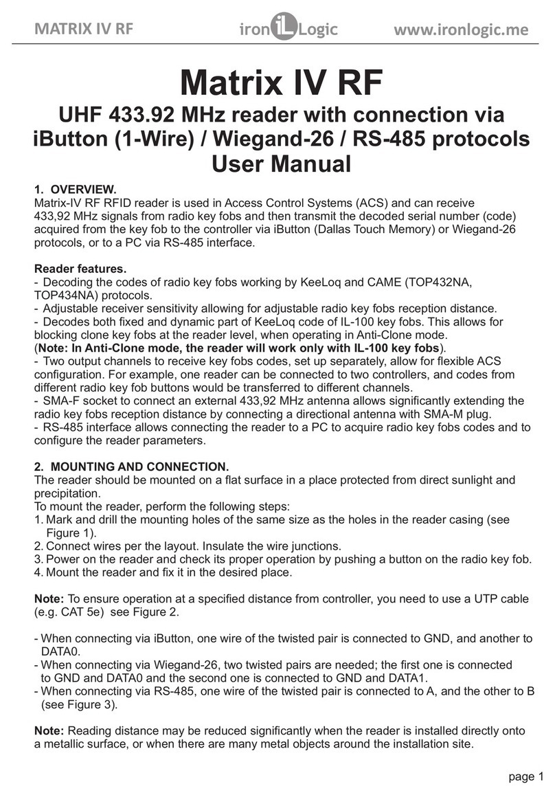
Iron logic Matrix II User manual

1. OVERVIEW
Matrix II K reader comprises the reader and controller in one case, and is used in Access Control
Systems (ACS) to operate electromagnetic and electromechanical locks by means of EM-Marine
contactless proximity cards.
The following equipment can be connected to a Matrix II K reader:
- External EM-Marine proximity card reader;
- Electromagnetic or electromechanical lock;
- Lock release button;
- External buzzer;
- External LED;
- Door sensor;
- iButton (Dallas Touch Memory) key probe.
2. SPECIFICATIONS
- Working frequency: 125 kHz
- Keys/key fobs standard: EM-Marine
- Maximum number of keys/cards: 1364
- Built-in EEPROM: Present
- Reading distance: 2…8 cm
- Power supply operating voltage: 12 V DC
- Maximum operating current: 45 mA
- Power output for lock: Field-effect-transistor.
- Maximum switching current for power output: 5 A
- Jumper for lock type selection: Yes, Electromechanical or electromagnetic positions
- Lock release duration timer: 0…220 s (factory default: 3 s)
- Audio-visual indication: Buzzer, bi-coloured LED
- Buzzer control: On/Off toggle
- Dimensions, mm: 85 x 44 x 18
- Case material: ABS Plastic
Figure 1: Reader Dimensions page 1
MATRIX II K www.ironlogic.me
Matrix II K
ACS RFID Reader 125 kHz & standalone controller
User Manual

3. OPERATING FACTS
- The term “Reader”is not an exact description of this device, as Matrix II K device comprises two
devices, a reader and a controller, in one case.
- In a reader + controller combo, the reader part only reads the ID numbers stored in proximity cards,
and transfers these IDs into the controller part.
- ACS actions depend on the existence of the card ID in the controller memory, and on its status,
which is assigned when recording the card. The “Card ID” is often called a “key”, so hereinafter in
this document we will consider “card” and “key” terms equivalent (e.g. “touch with a card” or “touch
with a key” mean the same). The full list of cards (keys),along with their statuses, is called “ACS
database”.
- Matrix II K programming only applies to the device's controller part: e.g. records the acquired card
ID along with its status, deletes the acquired card ID from device database, etc. The reader part of
Matrix II K device always performs the same operations: reading of the approached card ID and
transferring it to the controller part.
- To work with Matrix II K reader, each new proximity card must be assigned a “status” (owner
access rights). The status of the card is defined during its programming, on first swipe to the reader.
Possible status values are as follows:
- Master card used only for Matrix II K programming, and never for access.
- Normal (Access) card used for passing through access point (except Blocking Mode).
- Blocking card used for both passing through access point (including Blocking Mode), and
toggling the Blocking Mode on/off.
Note: The Blocking cards open the lock when they are being taken away from the reader.
- Initially, the memory of the controller part of a Matrix II K device is empty. To operate the controller,
first record a Master card into controller memory; with this Master card the device will be
programmed. See Chapter 4 on how to write a Master card.
ACS Operating Modes with Matrix II K:
- Standard Mode - access granted for Normal and Blocking cards.
- Blocking Mode - access granted for Blocking cards only, but denied for Normal cards. This mode
is activated by a Blocking card. Useful to temporarily restrict access down to a group of people.
- Accept Mode - access granted for existing Normal and Blocking cards, and for any new cards,
which in this mode are added into controller's memory as Normal cards. So after some time in this
mode, the controller will have built a new ACS database.
page 2
MATRIX II K www.ironlogic.me
ZUMM
TM
GND
EXIT
LED
LOCK
+12V
GND
DOOR
ADD
CLR
To increase
the built-in beeper
volume, please remove
the paper sticker.
Caps
1. External buzzer
2. TM central input
3. Common ground (-)
4. Door release button
5. External LED (+)
6. Lock
7. +12 V power
8. Common ground (-)
9. Door sensor (reed switch)
Places of laying
of a cable
LED
Figure 2: Reader PCB Layout

- Trigger Mode - emulates a simple lock operation logic. Each card touch changes the status of the
power key and hence, the lock status. Locking the power key generates a short beep, unlocking
two short beeps. This mode is normally used with electromagnetic locks, but other locking devices
can be also used. Please bear in mind, however, that locking devices not designed for extended
operating time, such as electromechanical locks, can eventually fail when operating in this mode.
Simple one-door ACS solution variants:
A. Entry and Exit by EM-Marine cards:
- On entry: Matrix II reader (or CP-Z reader where wiring is hidden) see Fig. 4;
- On exit: Matrix II K reader/controller + power supply + (electromagnetic lock OR
electromechanical lock/latch).
B. Entry by EM-Marine cards, Exit with a door release button:
- On entry: Matrix II K reader/controller;
- On exit: Door release button + power supply + (electromagnetic lock OR electromechanical
lock/latch).
Audio-visual status indication for the reader:
- In standby mode, the red LED is lit, to signal that power is supplied.
- When a card swipes the reader and it is:
- Present in Matrix II K controller database -- the green LED blinks, the buzzer sounds,
the lock is released for specified lock release duration (or until the door sensor is
triggered).
- Absent from Matrix II K controller database -- the LED blinks, 3-4 times alternating
between green and red, the buzzer sounds.
4. PROGRAMMING
When describing programming procedures, it is convenient to use the term “card touch to the reader”,
which we define as swiping the reader with a card close enough for reliable card ID acquisition (up to 2
cm).
Initial Matrix II K reader power-up (no keys in controller database yet).
Short beeps are sounding for 16 s after power-up, indicating that controller memory is empty and Add
Master Key mode is active.
While the beeps are sounding, touch the reader with a card. This will record the card number to memory
as a Master card (Master key). The short beeps stop sounding, thus confirming successful creation of a
first Master card.
To add more cards as Master cards, keep touching them to the reader with intervals less than 16 s
between them. Each touch the controller will acknowledge by a short beep. The Add Master Card mode
stops automatically after 16 s past the last touch, confirmed by a series of four short beeps.
During subsequent operation, the Master cards are used for programming.If no Master cards could be
stored, repeat the initial power-up procedure.
The Add Master Card mode is only activated when the controller database is empty (i.e. no
Normal, Blocking or Master cards stored).
page 3
MATRIX II K www.ironlogic.me

page 4
Table 1. Programming Modes
Common facts about programming
To put the controller into desired programming mode, use short (< 1 s) and long (~6 s) Master card
touches of the reader. Programming mode has a time-out (~16 s) for any actions; when this period is
over, the controller will revert to normal operation mode, informing by a series of four short beeps.
Mode 1. Add Normal and Blocking Card (1M)
Touch and hold (long touch) the reader with a Master card. On touch, the controller emits a short beep,
acknowledging the Master card recognition, and in 6 s, a second signal, denoting activation of Add
Normal and Blocking Cards mode. Take away the Master card now.
To add new cards, keep touching the reader with them, leaving no more than 16 s between touches.
Each new card touch is acknowledged by a short beep, which confirms recording the card number into
controller memory and assigning the card Normal status. If the card is still held at the reader for ~9 s
more, a long beep sounds and the card status changes to Blocking. If the card is already present in
controller memory, two short beeps will sound.
The Add Normal and Blocking Cards mode ends either automatically after 16 s after the last touch, or
with a Master card touch. The controller confirms the exit with a series of four short beeps.
Mode 2. Add Master Cards (1m, 1M)
Touch the reader once with a Master card (short touch). On touch, the controller emits a short beep,
acknowledging the Master card recognition. Within 6 s, touch and hold the Master card at the reader
(long touch). On that touch, the controller emits two short beeps, acknowledging the second Master
card touch, and in 6 s one more beep acknowledging that controller is now in Add Master Card mode.
Take away the Master card now.
To add more Master cards, keep touching the reader with new cards, leaving no more than 16 s between
the touches. The controller will confirm each new card touch by a short beep. If a card is already stored
in memory as Master card, no signals are emitted.
The Add Master Cards mode ends automatically after 16 s after the last touch. The controller confirms
the exit with a series of four short beeps.
MATRIX II K www.ironlogic.me
Modes Activation Legend
Programming using Master keys 1…5 – # of touches
* UPPERCASE letter –
Long touch (hold card for
~6 s)
* lowercase letter –
Short touch (hold card for
<1 s)
M – Master card
N – Normal card
B – Blocking card
Do NOT set the jumper in
any position not
described here – Risk of
damaging the device!
1. Add Normal and Blocking Cards 1M
2. Add Master Cards 1m, 1M
3. Erase Single Normal and Blocking Cards 2m, 1M
4. Erase All Memory 3m, 1M
5. Set Door Release Time 4m
6. Blocking Mode 1B
7. Accept Mode 5m
8. Storing Controller Memory to DS1996L Key 1m, 1M
9. Loading Information from DS1996L Key into
Controller Memory
Initial power-up
scenario
Programming using Jumpers
1. Electromechanical Lock Position 1
2. Erase All Memory Position 2
3. Add Normal Keys without Master Card Position 3
4. Electromagnetic Lock Position 4
5. Trigger Mode Position 5

page 5
Mode 3. Erase Single Normal and Blocking Cards with a Master Card (2m, 1M)
Touch the reader twice with a Master card (short touches). On first touch, the controller emits a short
beep, acknowledging Master card recognition. On second touch, the controller emits two short beeps,
acknowledging the second Master card touch in programming mode. Within 6 s, touch and hold the
Master card at the reader (long touch). On third touch, the controller emits three short beeps, and after 6
s one more beep, acknowledging that controller is now in Erase Single Cards mode. Take away the
Master card now.
To erase Normal and Blocking cards, keep touching the reader with them, leaving no more than 16 s
between the touches. Each erased card touch is acknowledged by a short beep; if that card is not
present in memory, by two short beeps.
The Erase Single Cards mode ends either automatically after 16 s from the last touch, or with a Master
card touch. The controller confirms the exit by a series of four short beeps.
Mode 4. Erase All Memory with a Master Card (3m, 1M)
Touch the reader 3 times with a Master card (short touches). On first touch, the reader emits a short
beep, acknowledging Master card recognition. On second touch, the reader emits two short beeps,
acknowledging the second Master card touch in programming mode. On third touch, the reader emits
three short beeps, acknowledging the third Master card touch. Within 6 s, touch and hold the Master
card at the reader (long touch). On fourth touch, the reader emits four short beeps, and after 6 s a series
of short beeps, acknowledging that controller memory has been erased and programming mode has
ended. Remove the Master card now. On next power-up, the reader will automatically enter the
programming mode.
Note: When the entire database is being erased with a Master card, the programmed Lock Release
Time is not reset.
Mode 5. Lock Release Time Programming (4m)
Touch the reader 4 times with a Master card. On each touch, the reader emits beeps acknowledging
Master card recognition; their count corresponds to the number of the touch. So, on fourth touch, the
reader emits four short beeps and enters the Lock Release Time Programming mode. Within 6 s from
the last touch, press and hold the lock release button for the necessary time to keep the lock open. After
the button is released, the reader emits a series of short beeps, records the time to memory and exits
programming mode.
Note: If the lock release button is not connected, connect terminals 3 and 4 on the reader PCB (Fig. 2)
Mode 6. Blocking Mode (1B)
In Blocking Mode, access is granted to Blocking cards only, but denied to Normal cards. Blocking Mode
is controlled by Blocking cards (see Mode 1 paragraph on how to add Blocking cards).
Blocking card is used:
- As a Normal card during normal operation (where access is granted to all Normal and Blocking cards
stored in controller memory).
- To activate Blocking Mode (so access is only granted to Blocking cards).
- To deactivate Blocking Mode and revert to normal operation.
The lock opens at the moment of removing Blocking cards from the reader.
To activate Blocking Mode on a controller, hold the Blocking card at the reader for ~3 s until a long
continuous beep sounds, acknowledging Blocking Mode activation. In this mode, attempting access via
a Normal card fails, and a series of short beeps is emitted.
To exit Blocking Mode into normal operation, either 1) touch and hold a Blocking card to the reader
(same sequence as Blocking Mode activation); or 2) touch the reader with a Master card quickly, -- a
series of short beeps will sound.
Note: If the supply power fails during Blocking Mode activated, it will stay active after the power is back
on.
MATRIX II K www.ironlogic.me
ZUMM
TM
GND
EXIT
LED
LOCK
+12V
GND
DOOR
ADD
CLR
jumpers
page 6
Mode 7. Accept Mode (5m).
Accept Mode is used to record all cards approaching the reader into controller memory, with Normal card
status. In this mode, a card approaching the reader opens the door and simultaneously gets stored into
controller memory as Normal card. This mode is used to recover the user database without collecting the
cards from the users.
To activate this mode, a Master card is required.Touch the reader 5 times with a Master card (short
touches). Each touch is accompanied by short beeps acknowledging the touch; the number of beeps
equals the touch number. So, on fifth touch, the controller emits five short beeps, then in 6 s, one more
long beep, acknowledging activation of Accept Mode.
To leave Accept Mode, touch the reader again with the Master card; a series of short beeps will
acknowledge the mode exit.
Note: If the supply power fails during Accept Mode activated, it will stay active after the power is back on.
Mode 8. Storing Controller Memory into a DS1996L Key (1m, 1M)
To record the controller memory into a DS1996L key, an iButton (Dallas Touch Memory) probe must be
connected to the reader (see Fig. 5).
Now activate Add Master Card mode, via a Master card. (See Mode 2 for description). For that, touch the
reader with that Master card (short touch). On touch, the reader emits a short beep, acknowledging the
Master card touch. Within 6 s, touch and hold the Master card at the reader (long touch). The reader emits
two short beeps, acknowledging second Master card touch, then in 6 s, a beep showing Add Master Card
mode activated on the device. Now touch the probe with DS1996L key and hold it until a series of short
beeps sounds. That would copy all keys information stored in the controller (the database), into the
DS1996L key. It is possible to copy this information from the DS1996L key into a computer, using a Z-2
Computer Adapter (Z-2 Base or Z-2 EHR).
Mode 9. Loading Information from a DS1996L Key into Controller Memory.
To load information from a DS1996L key into Matrix II K controller memory, an iButton (Dallas Touch
Memory) probe needs to be connected to the reader (see Fig. 6).
Please erase the Matrix II K controller's memory first (either by a Master card or by a jumper). Next, reboot
the device (turn it off and back on). Initial power-up scenario will run. Touch and hold the DS1996L at the
probe. When information transfer from DS1996L into controller memory is complete, a series of short
beeps will sound. Copying 1364 keys (maximum allowed number) into controller takes no longer than 25
s.
5. USING JUMPERS
One jumper comes with each Matrix II K reader for programming purposes. There are five valid jumper
positions (see Fig. 3).
Figure 3. Jumper Positions.
Position #1 - lock type selection: electromagnetic/electromechanical:
- Jumper not installed (or installed in default Position #4): Electromagnetic lock (when the lock is
closed, the voltage is on).
MATRIX II K www.ironlogic.me
page 7
- Jumper installed: Electromechanical lock (when the lock is closed, the voltage is off). Because
electromechanical locks require significant current (> 3 A), protective diode is recommended to use
with them (see Fig. 7). Also, use the protective diode when an electromagnetic lock has large traffic
(≥5 passes per minute), to protect the controller current choking circuit from overheating. It is also
important to use the power supply capable of providing necessary current to the lock.
Position #2, CLR (Clear) to clear controller memory. Power off the device, install the jumper into
Position #2 and power it on. When erasing is complete, a series of short beeps sounds.
Note: All keys are erased and programmed door release timer is reset to factory default (3 s).
Position #3, ADD (Addition) to add Normal and Blocking cards into controller memory without using the
Master card. Power off the controller, install the jumper into Position #3 and power it back on. After a
signal, the controller is in Add Normal and Blocking Cards Mode, without need for Master cards; a short
touch adds a Normal card, and a long touch a Blocking card. 16 s after the last card touch, the controller
leaves this mode.
Position #4 Jumper parking position (Default).Does not affect controller operation.
Position #5, Trigger Mode (for electromagnetic locks only). Power off the device, set the jumper into
Position #5 and power it on. In this mode, the controller can be in one of two positions: Locked (voltage is
being supplied to the lock), and Unlocked (no voltage being supplied to the lock). To toggle between
these positions, touch the reader with any Normal or Blocking card present in the device database.
The controller acknowledges the position toggle:
- Unlocked to Locked one short beep,
- Locked to Unlocked series of short beeps.
The managed lock should be connected to LOCK and +12V terminals on the Matrix II K reader.
Notice: Do NOT install the jumper into a position not described above. It can lead to device failure.
Important: Jumper socket can be also used to connect the reader to the computer, via a Z-2 Base
Computer Adapter (please refer to Z-2 Base computer adapter user manual for further information).
6. MOUNTING AND CONNECTING.
The device should be mounted on a flat surface in a place allowing for unfettered access by proximity
cards.
To mount a Matrix II K reader, perform the following steps:
- Mark and drill the holes for the reader case, of the same size as case holes (Fig. 1).
- Connect the external devices to reader terminals according to the connection layout. If the lock is
electromechanical, please install a protective diode (see Fig. 7), and the jumper into Position #1 (see
Fig. 3).
- Break out the protective tab in the reader's case and lead the cable into the opening. When the reader
is connected to power, the red LED comes on, and the reader goes into programming mode (Initial
power-up Writing Master cards see Chapter 4).
- Install the reader and fix it with the supplied screws.
- Close the openings in the reader case with the supplied protective tabs.
Note: For stable multiple readers operation, do not install adjacent readers closer than 10 cm from each
other.
MATRIX II K www.ironlogic.me
page 8
MATRIX II K www.ironlogic.me
Lock
ZUMM
TM
GND
EXIT
LED
LOCK
+12V
GND
DOOR
ADD
CLR
Optional external devices to connect:
- External buzzer;
- External LED;
- External button;
- Door sensor.
Door sensor
button
External buzzer
External LED
12V
DC
Figure 5. Connecting external devices
+12V
GROUND
DATA 0
DATA 1
LED-G
LED-R
BEEP
ZUMM
TM
GND
EXIT
LED
LOCK
+12V
GND
DOOR
ADD
CLR
Matrix II К
Matrix II
Figure 4. Connecting an external reader.
ZUMM
TM
GND
EXIT
LED
LOCK
+12V
GND
DOOR
ADD
CLR
TM
Matrix II К
Recommended diodes:
1N5400, 1N5821, HER301.
Probe
Figure 7. Connecting a protective diode.Figure 6. Connecting a probe.
Lock
+12V

page 9
7. OPERATING CONDITIONS
Ambient temperature: -30…40°C.
Humidity: Up to 80% at 25°C.
Device specifications may differ from described in this manual when operating under non-recommended
conditions.
8. PACKAGE CONTENTS
- Matrix II K Device: .....1
- Jumper: ....................1
- Protective tabs: .........2
- Screws 3*30: ............2
- Wall plugs: ...............2
9. LIMITED WARRANTY
Device is covered by limited warranty for 24 months.
The warranty becomes void if:
- this Manual is not followed;
- device has physical damage;
- device has visible traces of aggressive chemicals exposure;
- device circuits have visible traces of tamper by unauthorised parties.
While covered, the Manufacturer will repair the device or replace any broken parts, free of charge, where
fault is caused by manufacturer's defect.
MATRIX II K www.ironlogic.me
The symbol of crossed-throught waste bin on wheels means that the product
must be disposed of at f separate collection point. This also applies to the product
and all accessories marked with this symbol. Products labeled as such must not
be disposed of with normal household waste, but should be taken to a collection
point for recycling electrical and electronic equipment. Recycling helps to reduce
the consumption of raw materials, thus protecting the environment.
page 10
MATRIX II K www.ironlogic.me
10. IRONLOGIC CONTACTS
Headquarters:
RF Enabled ID Limited
34 Ely Place, London, EC1N 6TD, UK
E-mail: [email protected]
Development and production:
AVS LLC
7, Bobruiskaya street, Saint-Petersburg, 195009, Russian Federation
E-mail: [email protected]
Phone: +78122411853; +78125421185
www.ironlogic.ru
Authorized representative in the European Union:
SIA IRONLOGIC
79A, Slokas iela, LV-1007, Riga, Latvia
E-mail: [email protected], [email protected]
Phone: +37166181894; +37124422922
www.ironlogic.me
This manual suits for next models
1
Table of contents
Other Iron logic RFID System manuals

Iron logic
Iron logic Matrix II EH User manual

Iron logic
Iron logic MATRIX-V Instruction manual

Iron logic
Iron logic Z-2 USB MF User manual

Iron logic
Iron logic CP-Z-3 E User manual

Iron logic
Iron logic Matrix-IV RF User manual

Iron logic
Iron logic CP-Z-1 GSM User manual

Iron logic
Iron logic Matrix IV EHT Metal User manual

Iron logic
Iron logic Matrix V User manual

Iron logic
Iron logic CP-Z 2MF User manual