IFM DTE105 User manual

Operating instructions
RFID evaluation unit
DTE105
80293006 / 00 08 / 2020
UKUK

2
Content
1 Preliminary note���������������������������������������������������������������������������������������������������4
1�1 Symbols used ������������������������������������������������������������������������������������������������4
1�2 Warnings used�����������������������������������������������������������������������������������������������4
1�3 Copyright and trademarks �����������������������������������������������������������������������������4
2 Safety instructions �����������������������������������������������������������������������������������������������4
3 Functions and features ����������������������������������������������������������������������������������������5
3�1 Configuration via Ethernet interface ��������������������������������������������������������������6
3�2 RFID antennas ����������������������������������������������������������������������������������������������6
4 Items supplied������������������������������������������������������������������������������������������������������6
5 Function���������������������������������������������������������������������������������������������������������������6
6 Installation������������������������������������������������������������������������������������������������������������7
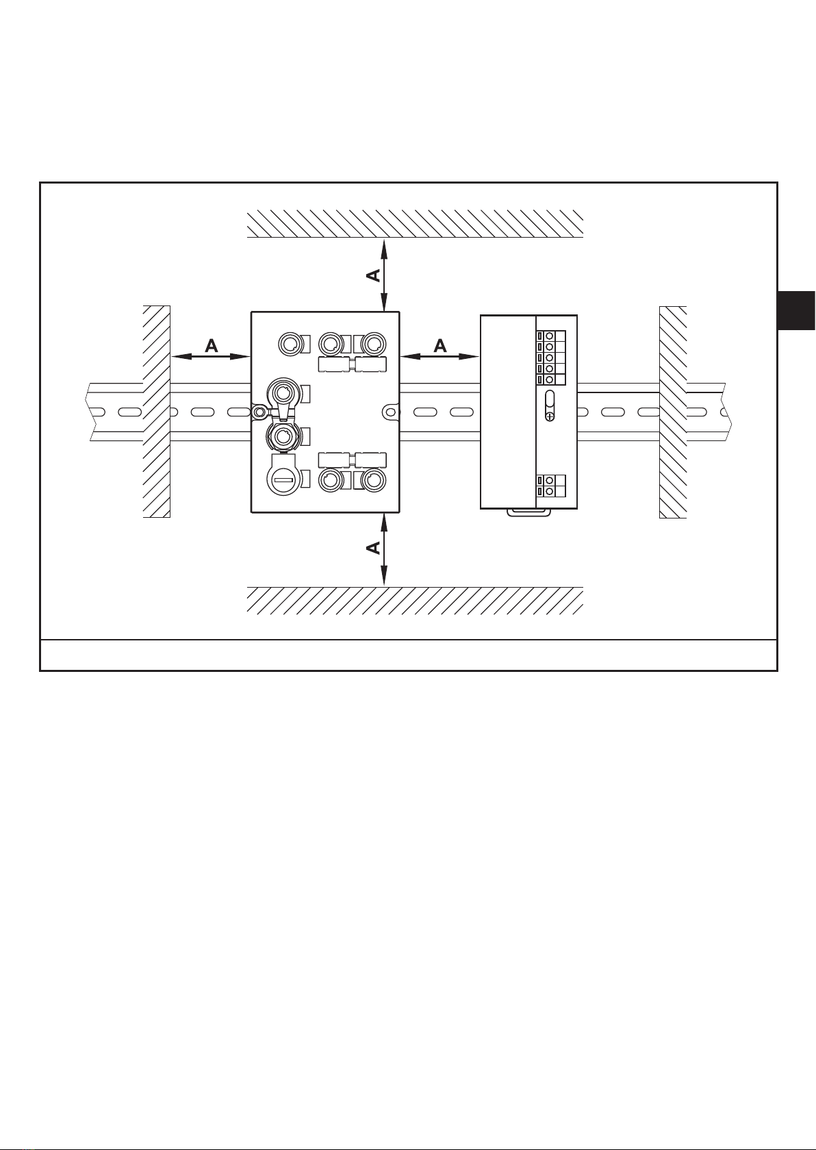
6�1 Installation distance ���������������������������������������������������������������������������������������7
6�2 Installation position ����������������������������������������������������������������������������������������8
6�3 Mounting options �������������������������������������������������������������������������������������������8
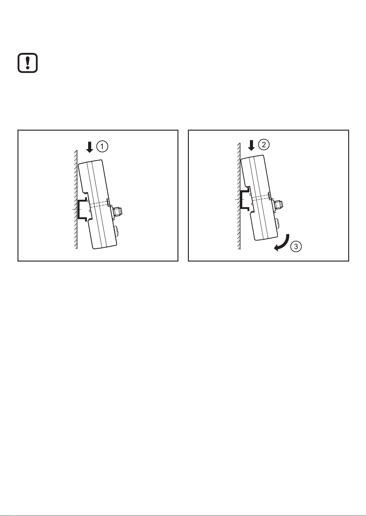
6�3�1 Mounting on DIN rail�����������������������������������������������������������������������������8
6�3�2 Removal �����������������������������������������������������������������������������������������������9
6�3�3 Mounting plate ��������������������������������������������������������������������������������������9
7 Electrical connection������������������������������������������������������������������������������������������10
7�1 AUX voltage supply �������������������������������������������������������������������������������������10
7�2 Network connection Ethernet port 1 / port 2 ������������������������������������������������ 11
7�2�1 Factory setting of the Ethernet parameters ���������������������������������������� 11
7�3 Process connections IO-1 ��� IO-4 ���������������������������������������������������������������12
7�4 Functional earth connection ������������������������������������������������������������������������13
7�4�1 Mounting on DIN rail���������������������������������������������������������������������������13
7�4�2 Mounting plate ������������������������������������������������������������������������������������13
8 Operating and display elements ������������������������������������������������������������������������14
8�1 Reset to factory settings ������������������������������������������������������������������������������14
8�2 LED indicators ���������������������������������������������������������������������������������������������14
8�2�1 LED AUX ��������������������������������������������������������������������������������������������14
8�2�2 LED Ethernet port 1 / port 2����������������������������������������������������������������15
8�2�3 LED SF �����������������������������������������������������������������������������������������������15
8�2�4 LED BF �����������������������������������������������������������������������������������������������15
8�2�5 LEDs IO1 ��� IO4 ���������������������������������������������������������������������������������16

3
UK
Licences and trademarks
Microsoft® und Internet Explorer® are registered trademarks of Microsoft
Corporation� All trademarks and company names are subject to the copyright of
the respective companies�
8�2�6 Special device LED indications ����������������������������������������������������������18
9 Technical data����������������������������������������������������������������������������������������������������18
9�1 Data sheets �������������������������������������������������������������������������������������������������18
9�2 Device manual���������������������������������������������������������������������������������������������18
10 Scale drawing ��������������������������������������������������������������������������������������������������19
11 Maintenance, repair and disposal ��������������������������������������������������������������������19
12 Approvals/standards ����������������������������������������������������������������������������������������19
12�1 Radio approvals�����������������������������������������������������������������������������������������20
12�1�1 Overview�������������������������������������������������������������������������������������������20
12�1�2 Europe / EC declaration of conformity����������������������������������������������20

4
1 Preliminary note
Technical data, approvals, accessories and further information: www�ifm�com
1.1 Symbols used
►Instructions
> Reaction, result
[…] Designation of keys, buttons or indications
→Cross-reference
Important note
Non-compliance may result in malfunction or interference�
Information
Supplementary note
1.2 Warnings used
NOTE!
Kind and source of the hazard
> Damage to property may result�
►Actions to refrain from�
►Measures to take�
1.3 Copyright and trademarks
© All rights reserved by ifm electronic gmbh� No part of these instructions may be
reproduced and used without the consent of ifm electronic gmbh�
All product names, pictures, companies or other brands used on our pages are the
property of the respective rights owners�
2 Safety instructions
• The device described is a subcomponent for integration into a system�
- The manufacturer is responsible for the safety of the system�
- The system manufacturer undertakes to perform a risk assessment and to
create a documentation in accordance with legal and normative requirements
to be provided to the operator and user of the system� This documentation
must contain all necessary information and safety instructions for the operator,

5
UK
the user and, if applicable, for any service personnel authorised by the
manufacturer of the system�
• Read this document before setting up the product and keep it during the entire
service life�
• The product must be suitable for the corresponding applications and
environmental conditions without any restrictions�
• Only use the product for its intended purpose (→ Functions and features).
• If the operating instructions or the technical data are not adhered to, personal
injury and/or damage to property may occur�
• The manufacturer assumes no liability or warranty for any consequences
caused by tampering with the product or incorrect use by the operator�
• Installation, electrical connection, set-up, operation and maintenance of the
product must be carried out by qualified personnel authorised by the machine
operator�
• Protect the device and the cables against damage�
• Use the device outside petrol stations, fuel depots, chemical plants or blasting
operations�
• Do not transport and store any flammable gases, liquids or explosive
substances near the device�
• Operation of the device can affect the function of electronic devices that are not
correctly shielded�
- Disconnect the device in the vicinity of medical equipment�
- Contact the manufacturer of the corresponding device in case of any
interference�
• Because of the requirements for electromagnetic interference emissions, the
device is intended for use in industrial environments� The device is not suitable
for use in domestic areas�
• Device safety: Use the device indoors only�
3 Functions and features
The RFID evaluation unit DTE105 integrates an Ethernet TCP/IP interface and 4
channels for the connection of field devices� Each channel can be used either for
the connection of an RFID antenna or as input/output to IEC 61131�

6
The device
• controls the data exchange to the RFID antennas or the sensor/actuator level�
• communicates with the higher-level control level via the ifm IoT Core protocol�
• allows device configuration via a web server�
Application examples:
• Material flow control in production lines
• Warehouse management by the automatic detection of stored products
• Tank management, order picking or product tracking
3.1 Configuration via Ethernet interface
• 10 Mbps and 100 Mbps
• TCP/IP - Transport Control Protocol / Internet Protocol
• ifm IoT Core protocol in JSON format
• IT functionality: HTTP server
• M12, twisted pair
3.2 RFID antennas
The device supports up to four RFID read/write heads of type ANT41x / ANT51x /
ANT60x from ifm electronic gmbh�
Accessories and further information: www�ifm�com
4 Items supplied
• RFID evaluation unit DTE105
• Installation instructions
The device is supplied without installation and connection accessories�
In the event of incomplete or damaged items supplied, please contact ifm
electronic�
5 Function
You can find detailed information about the function of the system in the device
manual at: www�ifm�com

7
UK
6 Installation
6.1 Installation distance
Due to the internal heating of the device a minimum distance to other objects of
10 mm is to be taken into account during installation�
A = 10 mm

8
6.2 Installation position
The installation position can be freely selected�
In a wet environment upside-down mounting is not permitted�
6.3 Mounting options
6.3.1 Mounting on DIN rail
The device can be installed on a DIN rail of type NS35/15 or NS35/7�5�
1� Angle the device and place the fixing clamp onto the upper edge of the DIN rail�
2� Press the device down�
3� Simultaneously rotate the device in the direction of the DIN rail�

9
UK
6.3.2 Removal
1� Press the device down�
2� Simultaneously rotate the device away from the DIN rail�
3� Remove the device from the top�
6.3.3 Mounting plate
The device can be fixed to the mounting plate using 2 screws (M4 x 35 or longer).
M4 M4
This installation mode is recommended for vibration and shock
requirements�

10
7 Electrical connection
The unit must be connected by a qualified electrician�
►Disconnect power before connecting the device�
►Observe the national and international regulations for the installation of
electrical equipment�
►Ensure voltage supply to EN 50178, SELV, PELV�
►Connect the device according to the indicated pin connection�
►A total current consumption of the device of 3 A must not be exceeded�
NOTE!
The IP rating indicated in the data sheet is only guaranteed if the
M12 connectors are firmly screwed�
The unit can be damaged by insufficiently tightened M12
connectors�
►Firmly screw the M12 connectors to the device�
Accessories and further information: www�ifm�com
Accessories ifm article number
Protective cap E73004
Torque wrench E70390
7.1 AUX voltage supply
►Connect the device to the voltage supply using an M12 connection cable�
3
12
4
5
Pin Connection
1 24 V DC
2 not used
3 0 V
4 not used
5 not used

11
UK
7.2 Network connection Ethernet port 1 / port 2
►Connect the device to an Ethernet 10BASE-T or 100BASE-TX capable device
using a suitable M12 Ethernet connection cable�
12
34
Pin Connection
1 TD+
2 RD+
3 TD-
Note: Screened connection
cable required
4 RD-
7.2.1 Factory setting of the Ethernet parameters
The following values are preset on delivery of the device:
Parameter Factory setting
IP address 192�168�0�79
Gateway address 192�168�0�100
Subnet mask 255�255�255�0
Auto-negotiation On
DHCP Off
The settings can be changed via the webserver of the device�

12
7.3 Process connections IO-1 ... IO-4
Each process connection can be used as input/output to IEC 61131 or for
connection of an RFID read/write head� The setting of the connections is made via
the command interface of the Ethernet TCP/IP connection of the Ethernet host�
3
12
4
5
Pin Connection
1 L+
2switching input (I/Q)
3 L-
4switching output (C/Qo) or input (C/Qi)
5 not used
The evaluation unit has to be disconnected before field units are connected�
Please note that the total current consumption of the device must not
exceed the value of 3 A�
You can find detailed information about the available operating modes in the
device manual at: www�ifm�com

13
UK
7.4 Functional earth connection
To ensure trouble-free operation the device must be connected to an earth
potential free from external voltage�
7.4.1 Mounting on DIN rail
The connection is made automatically via the DIN rail� Note that the DIN rail must
be connected with the earth potential�
7.4.2 Mounting plate
When the device is fixed on a mounting plate, connection is made via the left
fixing screw� Note that the plate must be connected with the earth potential�

14
8 Operating and display elements
8.1 Reset to factory settings
The Ethernet parameters can be reset to factory setting� Take the following steps:
►Remove all cable connections from the device�
►Insert an electrically conductive bridge between pin 1 and pin 3 on the process
connection IO-3�
►Connect the device with the voltage supply and wait until the yellow LED
indication on AUX and IO-3 flashes at approx� 8 Hz�
►Disconnect the device from the voltage supply and connect it again�
> The settings are reset�
8.2 LED indicators
The device indicates the current status of the interface via the status LEDs�
8.2.1 LED AUX
LED green LED
yellow
Status Note
Off Off No voltage supply UAUX < 5 V
On
Flashing
at
2 Hz
Voltage supply too low 5 V ≤ UAUX ≤ 18 V
On Off Voltage supply OK 18 V ≤ UAUX ≤ 36 V
On
Flashing
at
8 Hz
Firmware update running Do not switch off the device
during the firmware update

15
UK
8.2.2 LED Ethernet port 1 / port 2
LED green LED yellow Status Note
Off Off No connection to another
Ethernet counterpart Link status "no link"“
On Off
Connection to Ethernet
counterpart exists, no data
exchange
Link status "link", "no traffic"
On Flashes
sporadically
Connection to Ethernet
counterpart exists, data
exchange running
Link status "link", "traffic"
8.2.3 LED SF
LED red LED green Status Note
Off Off No voltage supply Check the voltage supply
Off On Normal operation -
Flashing Off Error on channel level
- Overload
- Temperature
- Internal fault
On Off Error on device level - Undervoltage
- Temperature
Flashing Flashing Self-test Starting phase of the device
8.2.4 LED BF
LED red LED green Status Note
Off Off No voltage supply Check the voltage supply
Off Flashing
Connection to the host
controller is established,
there is no data exchange
-
Off On
Connection to the host
controller is established,
there is data exchange
-

16
LED red LED green Status Note
Flashing Off
Connection to the host
controller is established, no
valid configuration
Check configuration
On Off No connection to the
host controller Check connection
Flashing Flashing Self-test Starting phase of the device
8.2.5 LEDs IO1 ... IO4
The LED indications of the process connections differ with each connection
configuration�
Use as input to IEC 61131
LED green LED yellow Status Note
Off Off Interface deactivated Interface was not configured
via the host controller
On Off Interface activated, input
on low level (0 V) -
On On Interface activated, input
on high level (24 V) -
Flashing
at
8 Hz
Flashing at
8 Hz Overload or short circuit -

17
UK
Use as output to IEC 61131
LED green LED
yellow Status Note
Off Off Interface deactivated Interface was not configured
via the host controller
On Off Interface activated, output
low-active (0 V) -
On On Interface activated, output
high-active (24 V) -
Flashing
at
8 Hz
Flashing
at
8 Hz
Overload or short circuit -
Use with RFID read/write heads
LED green LED
yellow Status Note
Off Off Interface deactivated Interface was not configured
via the host controller
Flashing
at
2 Hz
Off Interface activated, antenna
off -
On Off Interface activated, tag not
in the field -
On On Interface activated, tag in
the field -
Flashing
at
8 Hz
Flashing
at
8 Hz
Overload, short-circuit or
communication error -

18
8.2.6 Special device LED indications
LED Status Note
Green AUX LED on
Yellow AUX LED
flashing at 8 Hz
IO1���IO4 yellow LEDs
flashing at 8 HZ
Device is in the service mode
"emergency system started"�
A firmware update is
necessary and can be
executed via the web server�
Green AUX LED on
Yellow AUX LED
flashing at 8 Hz
IO1���IO4 green LEDs
flashing at 8 HZ
IO1���IO4 yellow LEDs
flashing at 8 HZ
Major error, device has to be
returned�
Hardware fault or permanent
data in the device are corrupt�
Green AUX LED on
Yellow AUX LED
flashing at 8 Hz
IO3 yellow LED
flashing at 8 Hz
Reset to factory settings -
9 Technical data
9.1 Data sheets
Data sheets can be found at: www�ifm�com
9.2 Device manual
The device manual can be found at: www�ifm�com

19
UK
10 Scale drawing
M12x1
M12x1
85
75 32,2
46,2
115
43,5
57,5
M4
11 Maintenance, repair and disposal
If used correctly, no maintenance and repair measures are necessary�
►The device must only be repaired by the manufacturer�
►After use dispose of the device in an environmentally friendly way in
accordance with the applicable national regulations�
►Keep the device free from soiling�
►Use glass cleaner as cleaning agent�
►Do not open the device�
12 Approvals/standards
If approval is granted the approval text of the respective countries applies
(→ 12 Approvals/standards).
Information about the approvals granted: www�ifm�com

20
12.1 Radio approvals
12.1.1 Overview
The overview of the approval status of a unit is available on our website at www�
ifm�com�
12.1.2 Europe / EC declaration of conformity
ifm electronic gmbh hereby declares that the DTE105 radio system corresponds to
the directive 2014/53/EU�
You can find the EC declaration of conformity on our website at: www�ifm�com
Table of contents
Other IFM RFID System manuals