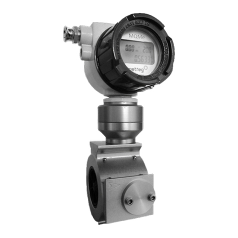
Metreg MQMe User manual

Instructions for Use
MQMe
Quantometer with
electronic meter index

Content
1
Area of application for the manual..................................................................................... 4
2
Basic safety instructions ....................................................................................................... 4
3
Manufacturer’s declaration.................................................................................................. 5
4
Applications for the MQMe Quantometer ........................................................................ 5
5
Design of the MQMe Quantometer.................................................................................... 6
6
Technical Data ........................................................................................................................ 7
7
Installation............................................................................................................................... 9
7.1 Requirements and recommendations .................................................................................................... 9
7.2 Installation location/direction of flow of the gas...............................................................................10
7.3 Equipment required for the installation...............................................................................................11
7.4 Implementation............................................................................................................................................12
8
Commissioning.....................................................................................................................15
9
Maintenance/lubrication....................................................................................................15
9.1 Maintenance..................................................................................................................................................15
9.2 Replacing the battery .................................................................................................................................16
9.3 Lubrication .....................................................................................................................................................18
10
Decommissioning ................................................................................................................19
11
Electronic meter index........................................................................................................20
11.1 Display .............................................................................................................................................................20
11.2 Buttons ............................................................................................................................................................21
11.3 Power supply.................................................................................................................................................21
11.4 Memory ...........................................................................................................................................................21
11.5 Integrated volume corrector (option) ...................................................................................................22
11.6 Pressure and temperature sensor...........................................................................................................22
11.7 Communication............................................................................................................................................22
12
Setting the parameters .......................................................................................................29
12.1 Preparation.....................................................................................................................................................29
12.2 Changing the primary address ................................................................................................................29
12.3 Changing the measuring range – 4 to 20 mA signal ........................................................................30
12.4 Changing the standard conditions (p and T) ......................................................................................30
12.5 Resetting the volume counter.................................................................................................................31
13
Measuring points..................................................................................................................32
13.1 Pressure measuring point .........................................................................................................................32
www.metreg-technologies.de

13.2 Temperature measuring point.................................................................................................................32
14
Cleaning .................................................................................................................................33
15
Transport and storage.........................................................................................................33
16
Disposal..................................................................................................................................33
17
Annex A ..................................................................................................................................34
18
Annex B ..................................................................................................................................35

1Area of application for the manual
This technical manual is intended for service personnel in the gas supply and gas
distribution industry who have received corresponding training and who possess technical
knowledge of the applicable technical rules and regulations as well as any higher level or
operational requirements. Some examples are specialists or employees who have been
trained in accordance with DVGW regulations G 492 and G 495 and are designated as
qualified experts.
2Basic safety instructions
Requirements for personnel
Work on the gas lines may only be carried out by suitable, reliable and trained personnel.
Operating personnel must be trained and authorized for their assigned tasks by the system
operator. Protective measures must be defined based on a risk assessment carried out in
accordance with Article 5 of the German Occupational Safety Act (ArbSchG).
Intended use
MQMe Quantometers are designed for the measurement of the volume of combustible
gases in the 1st, 2nd and 3rd families of gases (natural gas, town gas, propane, butane,
other combustible gases), processed and purified biogas and air, as well as other inert,
non-aggressive and non-explosive gases, that are used during operation. Depending on
the design of the meter, the permissible operating pressure range is up to 20 bar at a gas
temperature of between -20°C and +55°C.
The manufacturer is not liable for damages resulting from improper or inappropriate use.
Occupational safety
Wear the personal protective equipment stipulated by the applicable national regulations
when working on the meter.
Operational safety
The meter may only be operated in a technically flawless and operationally safe condition.
The operator is responsible for ensuring the operational safety of the device.
Product safety
The meter was manufactured and tested according to the latest technological standards. It
fulfills all legal requirements and complies with the relevant EC Directives. The
manufacturer declares this conformity by attaching the CE mark to the meter.
The meter left the factory in perfect condition. A manufacturer’s warranty is only provided
if the meter is installed and operated in accordance with the operating instructions.
4

3Manufacturer’s declaration
Declaration of Conformity (see Annex A, page 34)
4Applications for the MQMe Quantometer
The MQMe Quantometer is designed for metering the volume of natural gas used within a
company and is approved in accordance with European Regulation 2014/68/EU.
The MQMe Quantometer can be installed in potentially explosive atmospheres in category
1G (ATEX / IECEx Ex Zone 0) Ex ia II C T4 Ga (Annex B).
The MQMe Quantometer is suitable for measuring the volume of the following gases:
•Natural gas, town gas, propane, butane, ethylene, air, nitrogen and noble gases
•Other gases can be metered on request
Note: The MQMe Quantometer is not suitable for oxygen and highly corrosive gases,
acetylene and other aggressive gases or explosive gases and gas mixtures.
Note: The MQMe Quantometer
should not be used in the presence of strong
pulsations. These conditions will increase the number of measurement errors and
could significantly reduce the service life of the MQMe Quantometer.
5

5Design of the MQMe Quantometer
Meter structure
1
Meter housing
2
Turbine wheel
3
Electronic meter index
4
Magnetoresistive sensor
5
Flow straightener
6
Measuring unit housing
7
Measuring unit
Note: In the case of failure or damage:
Repairs may only be carried out by
qualified and authorized service
centers.
Fig. 1: Sectional drawing of the MQMe Quantometer
6

6Technical Data
Meter type
MQMe Quantometer
Approval
ATEX / IECEx Ex-Zone 1; Ex ia II C T4 Ga; PED 2014/68/EU
Size
G 10 to G 1000
Nominal diameter
DN 25 (1“) to DN 150 (6“)
Pressure rating
PN 16 and ANSI CLASS 150, PN4 with screw connection
Measuring range
1:20 (an exception is the DN 25 with a range of 1:10)
Temperature range
Gas temperature
Ambient temperature
Storage temperature
-
20°C to +55°C
-
25°C to +55°C
-
25°C to +55°C
Housing material
Aluminum
Max. operating temperature
20 bar overpressure
Accuracy
Q
min
≤ Q < Q
max
: ±1.0% von Q
max
Electronic meter index
Counter
Electronic index with 9 digits
Meter index head
Aluminum alloy
Protection class
IP 65
Battery
Lithium battery (calculated service life under standard
conditions of 5 years)
Display
LCD display for flow rate and volume under operating and
standard conditions, pressure and temperature, as well as
the status of the battery
Buttons
4 buttons
Memory
Non-volatile 512 k EEPROM memory for the parameters
and saving 1500 data records
Integrated volume corrector
(option)
AGA NX-19 or fixed factors
Standard conditions
selectable, standard configuration is 273.15
°K (0°C);
1013.25
mbar
Parameterization
Set in factory
Communication
Pulse outputs
1 HF pulser
Alternatively: 1 LF pulser
Opt
ional: additional 1 HF pulser (at the turbine wheel,
only with external power supply)
LF pulser (alternative)
Contact type
Normally open
Max. voltage
24 V
Max. current
110 mA
Max. resistance
5.1 Ω
Max. switching frequency f
max
10 Hz
7

HF pulser (standard)
Max. voltage
24 V
Max. current
110 mA
Max. resistance
5.1 Ω
Max. switching frequency f
max
1000 Hz
HF pulser
Additional inductive sensor according to NAMUR
(at the turbine wheel, only with external power supply)
Supply voltage
8.2 VCC (internal resistance 1 kΩ)
Power consumption
(sensor covered) <1 mA
Power consumption
(sensor free) >2.1 mA
Max. switching frequency f
max
1500 Hz
Analog output (option)
4–20 mA output (only with external power supply)
Serial communication (option)
M-Bus or Modbus/RS485 (Modbus/RS485 only with
external power supply)
Protocol
M-Bus, Modbus RTU
Working range and pulse weighting data
DN
[mm]
G-type
Qmin
[m3/h]
Qmax
[m3/h]
HF* [pulses/m3]
ext. pulser
HF* [pulses/m3]
int. pulser
L
[pulses/m3]
25
10
1.6
16
185,000–195,000
15,080–16,250
10
25
16
2.5
25
185,000–195,000
15,080–16,250
10
25
25
4
40
185,000–195,000
15,080–16,250
10
25
40
6.5
65
185,000–195,000
15,080–16,250
10
50
40
3.25
65
101,000–107,000
8,416–8,916
10
50
65
5
100
101,000–107,000
8,416–8,916
10
80
100
8
160
26,400–27,200
1,885–2,266
1
80
160
12.5
250
26,400–27,200
1,885–2,266
1
80
250
20
400
26,400–27,200
1,885–2,266
1
100
160
12.5
250
13,100–13,900
935–992
1
100
250
20
400
13,100–13,900
935–992
1
100
400
32
650
13,100–13,900
935–992
1
150
400
32
650
5,100–5,400
318–386
1
150
650
50
1000
5,100–5,400
318–386
1
150
1000
80
1600
5,100–5,400
318–386
1
*
The precise number of pulses is dependent on the meter size and the calibrated
meter itself. The stated values are typical numbers. The exact values determined for
each meter during the calibration are stated on the type plate for the HF sensor.
At the request of the customer, the LF output can be programmed with 100 pulses/m3, 10
pulses/m3, 1 pulse/m3or 0.1 pulses/m3.
8

7Installation
7.1 Requirements and recommendations
Before installing the Quantometer
1. Remove the protective film from the inlet and outlet of the meter.
2. Check the completeness of the meter (e.g. cover plugs, volume of oil supplied) and for
any possible transport damage.
3. Check that the turbine wheel rotates easily and stops smoothly, e.g. by blowing into the
MQMe Quantometer.
4. Ensure that there are no impurities, condensation, deposits or welding and drilling
residues in the pipeline. It is especially important to clean any elbow pipes in vertical
installations to prevent any damage if this dirt passes through the meter. A cone-
shaped startup filter can be installed to protect the meter during its initial operation.
This filter and the collected dirt should then be removed after 4–6 weeks at the latest to
prevent any disruption to the flow profile and thus a reduction in the measuring
accuracy.
5. In order to achieve a high level of accuracy, it is recommended that a straight inlet pipe
with a nominal size of ≥ 3 DN and an outlet pipe with a nominal size of ≥ 2 DN are used.
6. Vibrations and pulsations should be avoided at the measurement location. The
installation of a suitable compensator can effectively dampen this kind of interference.
7. Abrupt changes in the flow rate and strong pulsating flows of gas will increase
measurement errors. These issues can arise due to e.g. solenoid valves frequently
switching on and off. Pressure surges – especially due to the quick opening of valves –
can damage the ball bearing in the turbine wheel and cause the meter to fail during
prolonged operation.
8. Filters (with a small mesh size) should be installed upstream of the meter to protect it,
in particular, against dirt particles >50 µm both during startup and in continuous
operation.
9. The gas must be dry. If condensation occurs, it is recommended that a condensate
separator is installed upstream of the meter (a separator is already integrated into some
types of filter).
In this case, it is recommended that the meter
●is installed with a flow direction from the top to the bottom and
●not at the lowest point of the pipeline.
9

7.2 Installation location/direction of flow of the gas
The MQMe Quantometer can either be installed horizontally or vertically.
Horizontal installation
Fig. 2 Typical horizontal installation of the MQMe Quantometer (recommended)
Vertical installation
Fig. 3 Typical vertical installation of the MQMe Quantometer
Note:
The gas must flow in the direction of the arrow, see figure.
10

7.3 Equipment required for the installation
•Suitable and certified gaskets according to DIN EN 1514-1
•Screws according to DIN 976 DIN ISO 4014 and ASME B 1.1
•Nuts according to DIN 934 DIN EN ISO 4032 and ASME B 1.1
•Washers according to DIN EN ISO 7085 (DIN 125)
•Equipotential bonding with a minimum cross-section of 4 mm²
•For Quantometers with an oil pump: Oil according to the specifications Shell Morlina S2
BL 5 or Shell Morlina S2 BL 10
DN
[mm]
Pressure
ANSI
class
Flanges according to ANSI B 16.5
Threaded bolts with continuous thread and nuts
Min. operating
temperature of
the screws and
nuts
Number of
screws
Strength
class of the
screws
Strength class
of the nuts
Length of the
threaded rods
PN16
ANSI B16.5
Class150
25*
150
-25°C
4 x M12
ASTM A193
Grade B7
Grade 2H
50
150
-25°C
4 x M16
ASTM A193
ASTM A194
165
170
Grade B7
Grade 2H
165
170
80
150
-25°C
8 x M16
ASTM A193
ASTM A194
210
225
Grade B7
Grade 2H
210
225
100
150
-25°C
8 x M16
ASTM A193
ASTM A194
240
255
Grade B7
Grade 2H
240
255
150
150
-25°C
8 x M20
ASTM A193
ASTM A194
285
312
Grade B7
Grade 2H
285
312
*
Flange with threaded holes
DN
[mm]
Pressure
class PN
Flanges according to DIN EN 1092-1
Hexagon screws and nuts
Min. operating
temperature of
the screws and
nuts
Number of
screws
Strength
class of the
screws
Strength
class of the
nuts
Length of the
threaded rods
PN16
ANSI B16.5
Class150
25*
16
-10°C
4 x M12
5.6 / 8.8
50
16
-10°C
4 x M16
5.6 / 8.8
5 / 8
165
170
80
16
-10°C
8 x M16
5.6 / 8.8
5 / 8
210
225
100
16
-10°C
8 x M16
5.6 / 8.8
5 / 8
240
255
150
16
-10°C
8 x M20
5.6 / 8.8
5 / 8
285
312
*
Flange with threaded holes
11

DN
[mm]
Pressure
class PN
Flanges according to DIN EN 1092-1
Hexagon screws and nuts
Min. operating
temp. of the
screws and
nuts
Number of
screws
Screw
material
Nut
material
Length of the
threaded rods
PN16
ANSI B16.5
Class150
25*
16
-40°C
4 x M12
25CrMo4
50
16
-40°C
4 x M16
25CrMo4
25CrMo4
165
170
80
16
-40°C
8 x M16
25CrMo4
25CrMo4
210
225
100
16
-40°C
8 x M16
25CrMo4
25CrMo4
240
255
150
16
-40°C
8 x M20
25CrMo4
25CrMo4
285
312
*
Flange with threaded holes
7.4 Implementation
Installation of the MQMe Quantometer
1. Clean the flange surfaces (e.g. with petroleum).
2. The meter should preferably be installed horizontally with the meter index at the top.
3. The gas must flow in the direction of the arrow indicated on the meter.
4. During the installation, check that the gaskets are fitted concentrically so that no
sealing elements protrude into the pipeline.
5. In addition to the length of the meter itself, it is necessary to leave enough room for the
two gaskets between the inlet and outlet flanges for the installation.
6. The meter must be installed without any tension. For this purpose, ensure that the
meter axis is properly aligned with the pipeline axis.
7. Carry out a proper leak test of the flange connections.
8. If necessary, turn the general direction of the meter display by 180°, see “Changing the
turning range”, page 14.
1
Screw connection on the meter index head
9. Connect the equipotential bonding with a
minimum cross-section of 4 mm² to the
screw connection provided for this
purpose on the meter index head (1).
Fig. 4 Connection for the equipotential bonding
12

Check the following when installing the meter
1. The meter has been installed in the correct flow direction.
2. The meter has been installed without any leaks.
3. The meter has been installed without any tension.
●In a horizontal pipeline, the meter is installed with the meter index head in an
upright position. In the case of vertical installations, the oil pump (if present) must
be installed in an upright position.
●Connection screws and nuts must be tightened crosswise.
●See section 13, page 32, for instructions on connecting to the pressure measuring
points.
●See section 13.2, page 32, for instructions on connecting to the temperature
measuring points.
4. The angle of rotation of the meter display corresponds to the operator’s requirements,
see “Changing the turning range”, page 14.
It is recommended that a protective cover is fitted in the case of external installations.
After installing the meter: Welding work on the pipeline or on the flanges near to the
meter is not permitted.
13

Changing the turning range
The meter has a rotatable display with a turning range of 180° (A). The angle of rotation
can be changed to the other 180° (B) by turning the base by 180°.
1.
Loosen the 3 radial stud screws (1) on
the base of the meter index head.
2. Slightly lift up the meter index head
until the positioning pin (3) has been
completely pulled out of the drilled
hole (2).
3. Turn the meter index head by 180° in a
clockwise direction and lower it again
so that the pin is now seated in the
drilled hole on the opposite side (2).
4. Tighten the stud screws (1) again by
hand.
5. Make a note of the turning direction
so that if the meter index head is
adjusted again you can avoid turning
it in the same direction and possibly
damaging the cable connections.
1
Stud screws
2
Positioning pin
3
Drilled hole
14

8Commissioning
The MQMe Quantometers is commissioned after installation.
Commissioning of the MQMe Quantometer
1. For MQMe Quantometers with an oil pump: Lubricate the meter in accordance with
section 9.3, page 18:
2. Slowly open the valve upstream of the meter (Fig. 2 and Fig. 3) to pressurize the
pipeline up to the operating pressure.
3. The rate of increase in pressure should not exceed 350 mbar/s.
Attention:
Risk of damage due to pressure surges
4. When the operating pressure has been reached, the valve upstream of the meter can be
fully opened.
5. Slowly open the valve downstream of the meter (Fig. 2 and Fig. 3).
6. When the operating pressure has been reached, the valve downstream of the meter can
be fully opened.
7. Remove the startup filter after 4–6 weeks (if installed).
Attention:
Risk of damage due to foreign bodies in the line
Note: For MQMe Quantometers with an oil pump, the meter must be lubricated
before commissioning, see section 9, page 15.
9Maintenance/lubrication
9.1 Maintenance
1. MQMe Quantometers without oil pumps do not require any special maintenance. They
are maintenance-free.
2. MQMe Quantometers with oil pumps require regular maintenance, see section 9.3,
page 18:
3. The MQMe Quantometer may only be repaired by trained and authorized personnel,
e.g. service engineers from Metreg Technologies.
4. Replace the battery after a maximum of 5 years.
15

9.2 Replacing the battery
Note:
•
Only special lithium batteries from Metreg Technologies GmbH may be used.
•
Lithium batteries are subject to special safety rules with respect to their handling,
transport and storage. These rules must be observed. Especially due to their high
energy density, there is risk of fire if the batteries are handled incorrectly.
•
The cable connections (red & black) must NOT touch each other or be short
circuited. There is an acute risk of fire.
Attention: This also applies to replaced batteries!
•
The battery may only be replaced by a person trained in explosion protection.
•
The explosion protection regulations in the relevant country must be observed.
•
It is not permitted to replace the battery in a potentially explosive atmosphere.
•
No data transmission is possible while the battery is being replaced.
Order text
Order no.
Replacement set
Consisting of:
1x meter seal
1x lithium battery
1x instructions for
replacing the battery
88000255
Warning: Ensure that there are no short circuits
when replacing the battery.
Warning:
The battery may only be replaced in
an Ex zone if it has been guaranteed that the
area is Ex-free.
Fig. 5 Rear of the electronic meter index head
16

1
Seal
2
Screw
3
Cover
1. Remove the seal (1) on the rear of the
electronic meter index head.
2. Remove the screws (2) on the rear of
the electronic meter index head and
unscrew the cover (3).
Fig. 6 Safeguards on the rear cover
4
GND terminal
5
3.6 V terminal
6
Battery
Fig. 7 Terminals for connecting the battery
3. Remove the red and black wires from the GND terminal (4) and the 3.6 V terminal (5) on
the far right of the lower terminal block by pressing the clamping buttons.
4. Remove the battery (6) and insert the new battery in the same orientation.
5. Insert the red wire from the new battery into the 3.6 V terminal (5) and the black wire
into the GND terminal (4).
6. Check whether the battery symbol appears on the display.
Note: If the battery symbol flashes, the new battery is also nearly empty and must
be replaced, see section 11.3, page 21.
17

1
Seal
2
Screw
3
Cover
7
Sealing wire
8
Crosspiece
Fig. 8 Safety seal on the cover of the meter index head
1. Carefully close the rear cover (3) on the electronic meter index head and make sure that
none of the internal wires are jammed during this process. Fix the cover in place by
tightening the screw (2) by hand.
2. Seal the meter against unauthorized access again using the supplied safety seal (1).
3. To do this, insert the ends of the sealing wire (7) into the holes in the seal (1) from both
sides.
4. Then turn the crosspiece (8) in a clockwise direction until the wire has been inserted so
far that the crosspiece breaks.
9.3 Lubrication
Note: MQMe Quantometers with permanently lubricated ball bearings (no oil pump)
are maintenance-free. MQMe Quantometers with oil pumps require regular
lubrication, see section 9, page 15.
Process for the first lubrication
1. It is recommended that you only use oil sold by Metreg Technologies. A pack of oil for
the initial commissioning is supplied with the meter.
2. Approved oils are: Shell Morlina S2 BL 5 or Shell Morlina S2 BL 10.
3. Fill with oil before commissioning the meter and after correct installation as described
in section 7, page 9.
4. Add the correct volume of oil to the oil reservoir and then pull the pump lever in a
horizontal direction.
5. Depending on the size of the meter, the following strokes are required:
DN 50: 3 strokes
DN 80: 5 strokes
DN 100: 5 strokes
DN 150: 9 strokes
6. After completing the lubrication process, the oil reservoir should be closed tightly again
to prevent any contamination of the lubrication system.
18

Regular lubrication
1. Lubricate every 2–3 months if the gas is clean and a filter has been installed upstream of
the meter:
DN 50: 2 strokes
DN 80: 4 strokes
DN 100: 4 strokes
DN 150: 7 strokes.
2. If the gas is dirty or contains moisture, the meter should be lubricated at least every
month.
1
Pump lever
2
Oil reservoir cover
3
Oil reservoir
4
One-way valve
Fig. 9 Sectional drawing of the oil pump
10 Decommissioning
1. Ensure that there is sufficient ventilation in the installation room.
2. The gas may only be released into the free air and in locations where there are no active
ignition sources.
3. Reduce the operating pressure slowly (e.g. <350 mbar/s).
4. The screws and nuts on the flanges may only be removed when the pipeline has been
completely depressurized.
5. Carefully remove the meter from the pipeline.
19

11 Electronic meter index
11.1 Display
The display is a segment LCD display. The display is used to visualize the flow rate and
volume under operating and standard conditions, the pressure and temperature, as well as
the status of the battery. The display for the total volume of gas has 4 decimal places. The
meter index has 9 digits. 2 decimal places are displayed for the volumetric flow rate. The
maximum value is 9999 m3/h. If this value is exceeded, the display will flash.
Display 1
Display 2
The flow rate in the operating condition
(Qm, m3/h), the temperature (T,°C) –
determined as a fixed value or using a
temperature sensor – and the volume in
the operating state (Vm, m3) are shown on
the display.
The flow rate in the standard condition
(Qm, m3/h), the pressure (p, kPa) –
determined as a fixed value or using a
pressure sensor – and the volume in the
standard condition (Vb, N m3) are shown on
the display.
Note:
The
p
is shown quite close to the
h
but belongs to the pressure display.
20
Other manuals for MQMe
1
Table of contents
Other Metreg Measuring Instrument manuals
