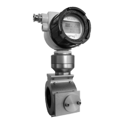
Metreg MQMe User manual

User Instructions
MQMe
Quantometer with electronic
meter index

Content
1
General information....................................................................................................................................................4
1.1 Manual.................................................................................................................................................................................................... 4
2
Safety..............................................................................................................................................................................4
2.1 Symbols.................................................................................................................................................................................................. 4
2.2 Personnel............................................................................................................................................................................................... 4
2.3 Intended use ........................................................................................................................................................................................ 5
2.4 Warranty ................................................................................................................................................................................................ 5
3
Applications for the MQMe Quantometer..............................................................................................................5
4
Design of the MQMe Quantometer..........................................................................................................................6
5
Technical Data..............................................................................................................................................................7
5.1 Working range and pulse weighting data................................................................................................................................. 8
6
Installation ....................................................................................................................................................................9
6.1 Requirements and recommendations........................................................................................................................................ 9
6.2 Installation location/direction of flow of the gas..................................................................................................................10
6.3 Required material.............................................................................................................................................................................11
6.4 Installation process..........................................................................................................................................................................12
6.4.1 Installation of the MQMe Quantometer ........................................................................................................................................................12
6.4.2 Checkpoints during and after installation of the MQMe Quantometer............................................................................................12
6.4.3 Changing the turning range ..............................................................................................................................................................................13
7
Commissioning.......................................................................................................................................................... 14
8
Maintenance/Lubrication........................................................................................................................................ 15
8.1 Maintenance.......................................................................................................................................................................................15
8.2 Lubrication of MQMe with oil pumps .......................................................................................................................................15
8.2.1 Lubrication during commissioning .................................................................................................................................................................15
8.2.2 Layout of the oil pump.........................................................................................................................................................................................15
8.2.3 Regular Lubrication................................................................................................................................................................................................15
9
Electronic Meter Index............................................................................................................................................. 16
9.1 Display..................................................................................................................................................................................................16
9.1.1 Pressure and temperature display...................................................................................................................................................................16
9.1.2 Display symbols.......................................................................................................................................................................................................17
9.1.3 Power Supply ...........................................................................................................................................................................................................17
9.1.4 Replacing the Battery............................................................................................................................................................................................18
9.2 Integrated volume corrector with compressibility factor calculation...........................................................................20
9.3 Communications data interface..................................................................................................................................................21
10
Connections............................................................................................................................................................... 23
10.1 MQMe without 4 – 20 mA, with external supply for the MQMe......................................................................................23
10.2 MQMe with external power supply for 4–20 mA and MQMe...........................................................................................23
10.3 MQMe with battery without external power supply for 4–20 mA .................................................................................24
10.4 MQMe operation in the Ex zone..................................................................................................................................................24
10.5 Switching example for the MQMe LF and HF output..........................................................................................................25
www.metreg-technologies.de

11
Parameter Setting..................................................................................................................................................... 26
11.1 Buttons.................................................................................................................................................................................................26
11.2 Preparation .........................................................................................................................................................................................26
11.3 Changing the Primary Address....................................................................................................................................................26
11.4Changing the maximum value for the 20 mA current output.........................................................................................27
11.5 Changing the Standard Conditions for Pressure and Temperature ..............................................................................27
11.6 Resetting the Volume Counter....................................................................................................................................................28
12
Measuring Points Pressure und Temperature..................................................................................................... 29
13
Cleaning...................................................................................................................................................................... 30
14
Transport and Storage............................................................................................................................................. 30
15
Außerbetriebnahme................................................................................................................................................. 30
16
Disposal....................................................................................................................................................................... 30
17
Annex A....................................................................................................................................................................... 31
18
Annex B....................................................................................................................................................................... 33
19
MQMe specification.................................................................................................................................................. 34

1 General information
1.1 Manual
This technical manual is intended for service personnel in the gas supply and gas distribution industry who have received
appropriate training and possess technical knowledge of the applicable technical standards as well as any higher-level or
operational requirements. Only specialists, trained and qualified personnel (e.g. DVGW G 492 and G 495), may carry out work
on the MQMe. The manual contains all information required to ensure safe and proper use of the device.
2 Safety
2.1 Symbols
The following symbols are used in this manual to indicate hazards or to provide information to assist the operators.
The manufacturer assumes no liability for damage resulting from improper or inappropriate use, nor for failure to follow the
instructions.
Risk of serious injury or even death!
There is a risk of serious injuries. Injuries can occur due to unprofessional handling or incorrect operation if the safety
instructions are not observed.
There is a possibility of damage to the device or the surrounding area if the instructions are not followed.
The measurement or the behavior of the device may also be affected!
2.2 Personnel
There is a significant risk of injuries. Injuries can occur due to unprofessional handling or incorrect operation and result in
serious injuries and, in the worst case, death if safety instructions are ignored.
•
Work on the gas lines
may only be carried out by suitable, reliable and trained personnel. Operating personnel must be trained and authorized
for their assigned tasks by the system operator. Protective measures must be defined based on a risk assessment carried
out in accordance with Article 5 of the German Occupational Safety Act (ArbSchG).
•
Occupational safety
Wear the personal protective equipment stipulated by the applicable national regulations and operator regulations
when working on the meter.
•
Operational safety
The meter may be used in technically flawless and operationally safe condition only. Responsibility rests with the
operator.
•
Product safety
The meter was manufactured and tested according to the latest state of the art. It fulfills all legal requirements and
complies with the applicable EC Directives. The manufacturer declares this conformity by attaching the CE mark to the
meter.
The meter left the factory in perfect condition. A manufacturer’s warranty is only provided if the meter is installed and
operated in accordance with the operating instructions. For manufacturer’s declaration and declaration of conformity
see Annex A, page 31.
4

2.3 Intended use
MQMe Quantometers are designed for the measurement of the volume of combustible gases in the 1st, 2nd and 3rd
families of gases (see also section 3 “Applications for the MQMe Quantometer”, page 5), processed and purified biogas and
air, as well as other inert, non-aggressive and non-explosive gases that are used during operation.
Depending on the variant, the permissible operating pressure range extends up to 16 bar absolute (ANSI 150 optional), the
gas temperature range from -20°C to +55°C.
No other use is authorized.
The manufacturer is not liable for damages resulting from improper or inappropriate use.
2.4 Warranty
Our General Terms and Conditions of Sale as most recently amended apply. Any deviating agreements do not restrict the
statutory rights of the consumer.
Any guarantee beyond this requires a contract and excludes software updates, consumables and vandalism to components.
3 Applications for the MQMe Quantometer
The MQMe Quantometer is designed for metering the volume of natural gas used within a company and is approved in
accordance with European Regulation 2014/68/EU.
The MQMe Quantometer can be installed in potentially explosive atmospheres in category 1G (ATEX/IECEx Ex Zone 0)
Ex ia II C T4 Ga (see Annex B, page 33).
•The MQMe Quantometer is suitable for measuring the volume of the following gases:
•Natural gas, town gas, propane, butane, ethylene, air, nitrogen, noble gases, liquid gas
•Biogas*
•Natural gas with a maximum H2content of 20%
•Other gases can be metered on request
The MQMe Quantometer is not suitable for oxygen and highly corrosive gases, acetylene and other aggressive gases
The MQMe Quantometer should not be used in the presence of strong pulsations. These conditions will increase the
number of measurement errors and could reduce the service life of the MQMe Quantometer.
Possible damage to the MQMe caused by aggressive gases
*Biogas – Please observe our special installation conditions, only in connection with installing an oil pump.
5

4 Design of the MQMe Quantometer
Meter structure
1
Meter housing
2
Turbine wheel
3
Electronic meter index
4
Magnetoresistive sensor
5
Flow straightener
6
Measuring cartridge
7
Measuring unit
Fig. 1: Sectional drawing of the MQMe Quantometer
In the case of failure or damage: Repairs may be carried out solely by qualified and authorized service centers and after prior
consultation with Metreg Technologies GmbH.
6

5 Technical Data
Meter data
Approval
ATEX 2014/34/EU/IECEx Ex-Zone (*in preparation);
Ex ia II C T4 Ga; PED 2014/68/EU
Size
G 10 to G 1.000
Nominal diameter
DN25 (1“) to DN150 (6“)
Pressure rating
PN 16 and ANSI CLASS 150, PN4 with screw connection
Measuring range
1:20, exception DN25 (1“ and 1,5“) with a range of 1:10
Temperature range
Gas temperature
Ambient temperature
Storage temperature
-20°C to +55°C
-25°C to +55°C
-25°C to +55°C
Housing material
Aluminum
Max. operating temperature
16 bar absolute (ANSI 150 optional)
Accuracy
Q
min
≤ Q <Q
max
: ±1.0% of Q
max
Electronic meter index
Counter
Electronic index with 9 digits
Meter index head
Aluminum alloy
Protection class
IP65
Battery
Lithium ion battery (calculated service life: 5 years under standard conditions, i.e. ambient
temperature 15–20°C/59–68°F)
Display
LCD display for flow rate and volume under operating and standard conditions for pressure,
temperature as well as battery status
Buttons
4 buttons
Memory
Non-volatile 512-k EEPROM memory for storage of parameters
Integrated volume corrector
(option)
Compressibility factor calculation according to AGA NX-19 or K = constant.
For version with pressure and temperature sensor (AGA NX-19) only with external power supply
Standard conditions
Standard pressure 1,013.25 mbar, standard temperature 273.15
K (0°C); standard pressure and
standard temperature are adjustable
Parameterization
Set in factory
Digital and analog outputs
LF pulser (standard)
Contact type
Max. voltage
Max. current
Max. resistance
Max. switching frequency f
max
Floating reed contact (open collector)
Normally open
24 V
110 mA
5.1 Ω
10 Hz
HF pulser (alternative)
Max. voltage
Max. current
Max. resistance
Max. switching frequency fmax
Floating reed contact (open collector)
24 V
110 mA
5.1 Ω
1,000 Hz
External HF pulser (option)
Supply voltage
Power consumption
Power consumption
Max. switching frequency f
max
Additional inductive sensor on the outside of the meter housing according to NAMUR (scanning at
the turbine wheel, only with external power supply)
8.2 VCC (internal resistance 1 kΩ)
(sensor covered) <1 mA
(sensor free) >2,1 mA
2,500 Hz
Analog output (option)
4–20 mA output (only with external power supply)
Data communication
RS485 interface (option)
Modbus RTU (only with external power supply)
M-Bus interface (option)
M-Bus
Frequent data retrievals on an MQMe in battery mode will affect battery life.
7

5.1 Working range and pulse weighting data
Type
G
-Type
DN/Rp Connection type
Measuring range
operating volume flow
Qb [m3/h]
Measurin
g range
ratio
pe
max. gas
HF* [pulses/m3]
ext. pulse
HF* [pulses/m3]
int. pulse
NF* [pulses/m3]
int. pulse
Pressure
drop
[mbar]
Qmin Qmax
MQMe
10
Rp 1“
Rp female thread
1,6
16
Rp 1“
4 bar
185.000–195.000
15.080–16.250
10
5
MQMe
16 Rp 1“ Rp female thread 2,5 25 Rp 1“ 4 bar 185.000–195.000 15.080–16.250 10 5
MQMe
25
Rp 1“
Rp female thread
4
40
Rp 1“
4 bar
185.000–195.000
15.080–16.250
10
5
MQMe
40 Rp 1“ Rp female thread 6,5 65 Rp 1“ 4 bar 185.000–195.000 15.080–16.250 10 5
MQMe
40
Rp 1½“
Rp female thread
6,5
65
Rp 1½“
4 bar
185.000–195.000
15.080–16.250
10
5
MQMe
10 DN25 Flange 1,6 16 DN25 16 bar 185.000–195.000 15.080–16.250 10 5
MQMe
16
DN25
Flange
2,5
25
DN25
16 bar
185.000–195.000
15.080–16.250
10
5
MQMe
25 DN25 Flange 4 40 DN25 16 bar 185.000–195.000 15.080–16.250 10 5
MQMe
40
DN25
Flange
6,5
65
DN25
16 bar
185.000–195.000
15.080–16.250
10
5
MQMe
40
DN50
Flange
6,5
65
DN50
16 bar
101.000–107.000
8.416–8.916
10
3
MQMe
65
DN50
Flange
5
100
DN50
16 bar
101.000–107.000
8.416–8.916
10
4
MQMe
100 DN80 Flange 8 160 DN80 16 bar 26.400–27.200 1.885–2.266 1 2
MQMe
160
DN80
Flange
12,5
250
DN80
16 bar
26.400–27.200
1.885–2.266
1
2
MQMe
250 DN80 Flange 20 400 DN80 16 bar 26.400–27.200 1.885–2.266 1 4
MQMe
160
DN100
Flange
12,5
250
DN100
16 bar
13.100–13.900
935–992
1
3
MQMe
250
DN100
Flange
20
400
DN100
16 bar
13.100–13.900
935–992
1
3
MQMe
400
DN100
Flange
32
650
DN100
16 bar
13.100–13.900
935–992
1
6
MQMe
400 DN150 Flange 32 650 DN150 16 bar 5.100–5.400 318–386 1 10
MQMe
650
DN150
Flange
50
1.000
DN150
16 bar
5.100–5.400
318–386
1
10
MQMe
1.000 DN150 Flange 80 1.600 DN150 16 bar 5.100–5.400 318–386 1 10
*
The precise number of HF pulses is dependent on the meter size and the calibrated meter itself. The stated values are
typical numbers. The exact values determined for each meter during the calibration are stated on the type plate for the
HF sensor.
8

6 Installation
6.1 Requirements and recommendations
Risk of injury from explosion!
Unprofessional planning and mounting can lead to explosion hazards:
•Escaping flammable gas in case of system leaks
•Bursting of the system due to the applied gas pressure in case of insufficient strength of components or incorrect
assembly
Therefore, please note:
•All work on the gas supply system must be carried out by trained personnel only, see also section 2.2 “Personnel”,
page 4
•Observe DVGW rules and regulations. Observe national regulations.
•Carefully observe these operating instructions.
The following instructions are intended to support smooth installation of the MQMe Quantometer in the measuring system
in order to prevent damage.
1. Remove the protective film from the inlet and outlet of the meter.
2. Check the completeness of the meter (e.g. cover plugs, volume of oil supplied) and for any possible transport damage.
3. Check that the turbine wheel rotates easily and stops smoothly, e.g. by blowing into the measuring cartridge of the
MQMe Quantometer.
4. Ensure that there are no impurities, condensation, deposits or welding and drilling residues in the pipeline. It is
especially important to clean any elbow pipes in vertical installations to prevent any damage if this dirt passes through
the meter. A cone-shaped startup filter can be installed to protect the meter during its initial operation. This filter and the
collected dirt should then be removed after 4–6 weeks at the latest to prevent any disruption to the flow profile and thus
a reduction in the measuring accuracy
5. In order to achieve a high level of accuracy, it is recommended that a straight inlet pipe with a nominal size of ≥ 3 DN
and an outlet pipe with a nominal size of ≥ 2 DN are used.
6. Vibrations and pulsations should be avoided at the measurement location. The installation of a suitable compensator
can effectively dampen this kind of interference.
7. Abrupt changes in the flow rate and strong pulsating flows of gas will increase measurement errors. These issues can
arise due to e.g. frequently switching on and off the gas flow with solenoid valves. Pressure surges due to the quick
opening of valves can damage the ball bearings in the turbine wheel and cause the meter to fail.
8. Filters (with a small mesh size) should be installed upstream of the meter to protect it, in particular, against dirt particles
>50 µm both during startup and in continuous operation.
9. The gas must be dry. If condensation can occur, it is recommended that a condensate separator is installed upstream of
the meter (a separator is already integrated into some types of filter). In this case, it is recommended that the meter be
installed:
‒with a flow direction from the top to the bottom, and
‒not at the lowest point of the pipeline.
9

6.2 Installation location/direction of flow of the gas
1
The arrow on the housing indicates the
correct gas flow direction through the
MQMe.
The MQMe Quantometer can either be installed horizontally or vertically.
Horizontal installation
FQ
MQMe
Filter
Bypass
Fig. 2: Recommended horizontal installation of the MQMe, orange arrows indicate gas flow direction
Vertical installation
FQ
MQMe
Filter
Bypass
Fig. 3: Typical vertical installation of the MQMe
The specified gas flow direction must be observed.
Possible damage to the MQMe caused by excessive temperatures
When the MQMe is installed, welding work on the pipe system in the vicinity of the MQMe is not permitted.
10

6.3 Required material
•Suitable and certified gaskets according to DIN EN 1514-1
•Screws according to DIN 976 DIN ISO 4014 and ASME B 1.1
•Nuts according to DIN 934 DIN EN ISO 4032 and ASME B 1.1
•Washers according to DIN EN ISO 7085 (DIN 125)
•Equipotential bonding with a minimum cross-section of 4 mm²
•For Quantometers with an oil pump: Oil according to the specifications Shell Morlina S2 BL 5 or Shell Morlina S2 BL 10
Flanges according to DIN EN 1092-1: Hexagon screws and nuts
DN
[mm]
Pressure
class PN
Screws and nuts
Operating temperature
Screws DIN 125
Quantity/size/washer
Strength class/material Length of the
threaded rods
Screws Nuts
25*
16 -10°C
8 x M12x35**/B13-140HV
5.6/8.8/25CrMo4 5/8/25CrMo4
35
50
4 x M16x165***/B17-140HV
165
80
8 x M16x210***/B17-140HV
210
100
8 x M16x240***/B17-140HV
240
150
8 x M20x285***/B21-140HV
285
*
Flange on both sides with blind hole thread
**
Hexagon head screws ISO 4017, EN 1515-4
***
Screw bolt DIN 976-1 Form-B, EN 1515-4
Flanges according to ANSI B 16.5 – Threaded bolts with continuous thread and nuts
DN
[mm]
Pressure
class ANSI Screws and nuts
Min. operating temperature
No. of screws Strength class
Length of threaded rods
ANSI B16.5 Class150
Screws Nuts
25*
150
-25°C
8 x M12x35
ASTM A193 Grade B7
Grade 2H
50
150
-25°C
4 x M16
ASTM A193 Grade B7
ASTM A194
170
80
150
-25°C
8 x M16
ASTM A193 Grade B7
ASTM A194 Grade 2H
225
100
150
-25°C
8 x M16
ASTM A193 Grade B7
ASTM A194 Grade 2H
255
150
150
-25°C
8 x M20
ASTM A193 Grade B7
ASTM A194 Grade 2H
312
*
Flange on both sides with blind hole thread
11

6.4 Installation process
6.4.1 Installation of the MQMe Quantometer
1. Clean the flange surfaces (e.g. with petroleum).
2. It is recommended to install the MQMe horizontally, with the meter index pointing upwards.
3. Ensure that the gas flow is in the direction of the arrow on the MQMe.
4. Ensure that the seals are mounted concentrically so that no seal parts protrude into the pipeline.
5. In addition to the length of the MQMe, provide enough room for the two gaskets between the inlet and outlet flanges
for the installation.
6. Install the MQMe without any tension. For this purpose, ensure that the meter axis is properly aligned with the pipeline
axis.
7. Carry out a proper leak test of the flange connections.
8. If necessary, turn the general direction of the meter display by 180°, see section 6.4.3“Changing the turning range”,
page 13.
1
Screw connection on the meter index head for connecting an
equipotential bonding cable with a minimum cross-section of
4 mm².
Fig. 4: Connection for the equipotential bonding
6.4.2 Checkpoints during and after installation of the MQMe Quantometer
1. The MQMe is installed in the correct flow direction, see also section 6.2 “Installation location/direction of flow of the gas”,
page 10.
2. The MQMe has been installed without any leaks.
3. The MQMe has been installed without any tension.
‒In a horizontal pipeline, the MQMe is installed with the meter index head in an upright position. In the case of vertical
installations, the oil pump (if present) must be installed in an upright position.
‒Connection screws and nuts must be tightened crosswise.
‒See section 12 “Measuring Points Pressure and Temperature”, page 29 for instructions on connecting to the pressure
measuring points.
‒See section 12 “Measuring Points Pressure and Temperature”, page 29 for instructions on connecting to the
temperature measuring points.
4. The angle of rotation of the meter display corresponds to the operator’s requirements, see section 6.4.3“Changing the
turning range”, page 13.
We recommend a protective cover in the case of external installations.
12

6.4.3 Changing the turning range
The MQMe has a rotatable display with a turning range of 180°(A). The angle of rotation can be changed to the other 180°(B)
by turning the base by 180°.
Fig. 5: Rotation of the meter head
1.
Loosen the 3 radial stud screws (1) on the base of the meter index head.
2. Slightly lift up the meter index head until the positioning pin (3) has been
completely pulled out of the drilled hole (2).
3. Turn the meter index head by 180° in a clockwise direction and lower it again so
that the pin is now seated in the drilled hole on the opposite side (2).
4. Tighten the stud screws (1) again by hand.
5. Make a note of the turning direction so that if the meter index head is adjusted
again you can avoid turning it in the same direction and possibly damaging the
cable connections.
1
Stud screws
2
Positioning pin
3
Drilled hole
13

7 Commissioning
The MQMe is commissioned after completed installation.
Commissioning may be carried out only by authorized specialist personnel. The system may be cleared for unsupervised
operation only after commissioning has been carried out correctly.
The following instructions must be observed carefully to avoid damage to the MQMe.
1. MQMe with oil pump: Lubricate the meter in accordance with section 8.2 “Lubrication of MQMe with oil pumps”,
page 15.
2. For filling of the gas line, carefully open the shut-off valve directly upstream of the MQMe (Fig. 2 and Fig. 3) until the
operating pressure is reached. The rate of increase in pressure should not exceed 350 mbar/s.
The MQMe may be damaged by pressure surges, see also “Pressure surges”, page 9.
3. After reaching the operating pressure, the shut-off valve can be opened completely.
4. Carefully open the shut-off valve directly downstream of the MQMe (Fig. 2 and Fig. 3) until the operating pressure is
reached.
5. After reaching the operating pressure, the shut-off valve can be opened completely.
6. If startup filters are installed, they can be removed after 4–6 weeks.
Possible damage to the MQMe due to foreign bodies in the pipeline if startup filters are missing!
14

8 Maintenance/Lubrication
8.1 Maintenance
The MQMe may be maintained and repaired only by trained and authorized personnel, e.g. service engineers of Metreg
Technologies GmbH.
Replace the battery after a maximum of 5 years.
MQMe without oil pumps do not require any special care. They are maintenance-free.
MQMe with oil pumps require regular lubrication.
8.2 Lubrication of MQMe with oil pumps
8.2.1 Lubrication during commissioning
It is recommended that you use only oil sold by Metreg Technologies GmbH. A bottle of oil for the initial commissioning is
supplied with the MQMe.
Approved oils are: Shell Morlina S2 BL 5 or Shell Morlina S2 BL 10.
1. Fill in the oil after completing the correct installation according to section 6 “Installation”, page 9, and before starting up
the MQMe. For this purpose, open the oil reservoir cover (2, Fig. 6) and fill in the appropriate amount of oil.
2. Depending on the size of the MQMe, operate the pump lever:
DN50: 3 strokes
DN80: 5 strokes
DN100: 5 strokes
DN150: 9 strokes
3. Once lubrication is complete, ensure that sufficient oil remains in the oil reservoir for re-lubrication, then close the oil
reservoir cover tightly to prevent any contamination in the lubrication system.
8.2.2 Layout of the oil pump
Fig. 6: Sectional drawing of the oil pump
1
Pump lever
2
Oil reservoir cover
3
Oil reservoir
4
One-way valve
8.2.3 Regular Lubrication
Lubricate every 2–3 months if the gas is clean and a filter has been
installed upstream of the meter.
Lubricate at least every month, if the gas is dirty or contains moisture.
DN50: 2 strokes
DN80: 4 strokes
DN100: 4 strokes
DN150: 7 strokes
15

9 Electronic Meter Index
9.1 Display
The meter indexes for operating and standard volume, the flow rates for operating and standard volume flow as well as
pressure and temperature are shown on a segment LCD display. In addition, status information and faults are displayed.
Operating values and
temperature
Standard values and pressure
1
Flow rate Q
b
in m³/h, 2 decimal places
5
Flow rate Q
n
in m³/h, 2 decimal places
2
Temperature T in °C, 1 decimal place
6
Pressure p in kPa, 1 decimal place (the symbol p is located directly next to the
unit Nm³/h)
3
Meter index V
b
in m³, 4 decimal places
7
Meter index V
n
in Nm³, 4 decimal places
4
Battery symbol
9.1.1 Pressure and temperature display
Pressure and temperature displays can be used only when the volume corrector is activated (AGA or compressibility factor
constant).
If no pressure and temperature sensor was selected in the configuration of the MQMe, the substitute values are displayed.
These must be known when ordering the MQMe. If the MQMe is equipped with pressure and temperature sensor, the last
valid measured value is displayed in case of failure of a sensor.
16

9.1.2 Display symbols
A battery symbol (4) is also shown at the bottom right of the display behind the meter index readings.
Power supply display
If the battery voltage is insufficient, the battery symbol flashes, see also section 9.1.4 “Replacing the Battery”, page 18.
If the MQMe is additionally connected to the mains supply, a plug symbol is displayed above the battery symbol. If the plug
symbol is not displayed, the power supply must be checked.
If the battery symbol flashes while the mains supply is connected, no battery is inserted in the MQMe, or the battery plug is
not connected to the MQMe.
Indication of pressure sensor failure
If the pressure sensor fails, the
p
and
kPa
symbols of the pressure display start flashing. For further internal processing, the
last valid measured value before the failure of the pressure sensor is used.
Indication of temperature sensor failure
If the temperature sensor fails, the
T
and
°C
symbols of the temperature display start flashing. For further internal
processing, the last valid measured value before the failure of the temperature sensor is used.
Flow rate limit violation at the 4–20 mA output
When the meter displays 0 (no flow), a current of 4 mA is output. If the flow exceeds the maximum flow value Qmax, a current
of 20 mA is output.
Failure of pressure and temperature sensors plus power supply
If the pressure and temperature sensors and the power supply fail, and if the pressure and temperature sensors continue to
malfunction after the power supply has been restored, the fixed substitute values for pressure and temperature are used
until the pressure and temperature sensors start working properly again.
Flow sensors failure
The meter indexes stop, and no flow is displayed. The current output decreases to 4 mA and outputs 4 mA permanently.
9.1.3 Power Supply
The MQMe is powered by an internal 3.6 V lithium battery with a power consumption of <0.7 mW or by a direct 24 VDC
mains supply.
The calculated service life of the lithium battery under standard conditions (temperature 5–25°C/41–77°F) is 5 years. The
charging status of the battery is shown on the LCD display. When the battery voltage drops below 3.0 V, the battery symbol
starts flashing. The battery must be replaced within 30 days. The voltage of the internal lithium battery is monitored
continuously.
Alternatively, the MQMe Quantometer can also be operated with line voltage only. The internal battery is not active in this
case, and additionally a power plug symbol is displayed above the battery symbol. When it is connected to the mains
supply, the MQMe can be operated without a battery as well. The battery symbol flashes continuously in this case.
17

9.1.4 Replacing the Battery
Ensure the following before changing the battery:
•Use only special lithium batteries by Metreg Technologies GmbH. The batteries are equipped with a plug that prevents
mix-up of the connections.
•For systems in hazardous areas, only a person trained in explosion protection may replace the battery.
•Ensure that no gas is present before carrying out the work!
•Observe the locally applicable explosion protection requirements.
Risk of fire!
•Observe the general safety instructions for handling lithium batteries (new or replaced)!
•Ensure that the cable connections (red and black) on the connecting plug do not touch or are short-circuited.
•There must be no explosive atmosphere during the replacement of the battery.
It must be guaranteed that the area is not hazardous!
The manufacturer assumes no liability for damages resulting from improper battery replacement.
No data transmission is possible while the battery is being replaced.
Reordering of replacement batteries
Order no.
Order text
88000255
Replacement set consisting of:
1 x meter seal
1 x lithium battery
1 x replacement instructions
Fig. 7: Battery connection
1
Seal
2
Screw
3
Cover
1. Remove the seal (1) on the rear of the
electronic meter index head.
2. Loosen the screws (2) on the rear of the
electronic meter index head and unscrew
the cover (3).
Fig. 8: Seal and safety screw
18

Fig. 9: Battery position
4
Battery
Fig. 10: Connection of the battery
4
Battery
5
Plug
3. Pull off the plug (5) with the black and red
cable.
4. Plug the plug (5) of the new battery in the
connector.
5. Position the new battery in the battery
holder.
6. The connection is OK when the battery
symbol is shown on the display.
Fig. 11: Closing the housing
1
Seal
2
Screw
3
Cover
7
Sealing wire
8
Crosspiece
1. Carefully screw down the rear cover (3) on the electronic meter index head and make sure that none of the internal wires
are jammed.
2. Secure the cover against unscrewing using the screw (2).
3. Seal the meter against unauthorized access again using the supplied safety seal (1).
4. To do this, insert the ends of the sealing wire (7) into the holes in the seal (1) from both sides.
5. Turn the crosspiece (8) in a clockwise direction until the wire has been inserted so far that the crosspiece breaks.
19

9.2 Integrated volume corrector with compressibility factor calculation
With external pressure and temperature sensor
If the MQMe features the option of compressibility factor calculation (compressibility calculation), the values for the density
ratio dv and the CO2and N2content of the gas must be known. If a pressure and temperature sensor is also integrated, the
compressibility of the gas is continuously determined using the AGA NX-19 equation.
Pressure and temperature sensor are connected to the MQMe via a bus interface. The temperature sensor operates in the
range from –25°C to +100°C. There are three absolute pressure sensors available for pressure measurement:
0.1–5 bar, 2–10 bar and 6–20 bar.
Without pressure and temperature sensor
If no pressure and temperature sensor is integrated in the MQMe, the compressibility factor of the gas can be determined
using a fixed pressure and temperature. In this case, the compressibility factor can be calculated once if required and stored
as a constant value in the MQMe.
Conversion (state number)
Conversion of the operating volume to the standard volume:
ZU
State number (C *)
pn
Standard pressure (101.325 kPa)
t
Gas temperature (°C)
Tn
Standard temperature (273.15 K = Kelvin)
K
Compressibility factor
p
Pressure (kPa)
*
International designation
The calculation of compressibility and state number is based on standard pressure and standard temperature.
The standard temperature is not identical in all countries.
Any deviations from the local standard values (101.325 kPa and 0°C = 273.15 K) for the country in which the MQMe is to be
used must be known.
Conversion (standard volume and standard volume flow)
V
n
= V
b
* ZU
Q
n
= Q
b
* ZU
V
n
Standard volume Nm³ (V
b
*)
V
b
Operating volume m³ (V
m
*)
ZU
State number (C *)
Q
n
Standard volume flow Nm³/h (Q
b
*)
Q
b
Operating volume flow m³/h (Q
m
*)
*
International designation
Pressure and temperature sensor
If an external pressure and temperature sensor is connected to the MQMe Quantometer, the necessary wiring is described in
section 10 “Connections”, page 23.
Communication with the external sensors is via a bus system.
Pressure sensors with measuring ranges of 5, 10, and 20 bar absolute pressure are supported.
20
Other manuals for MQMe
1
Table of contents
Other Metreg Measuring Instrument manuals
