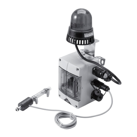
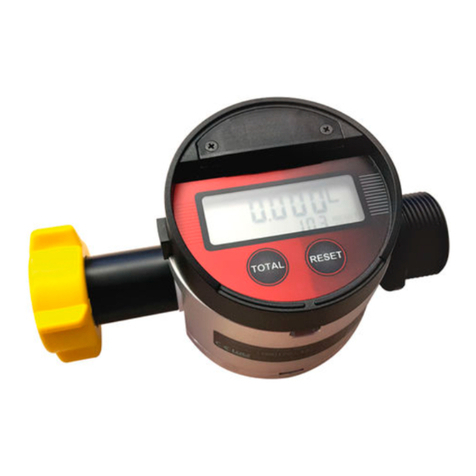
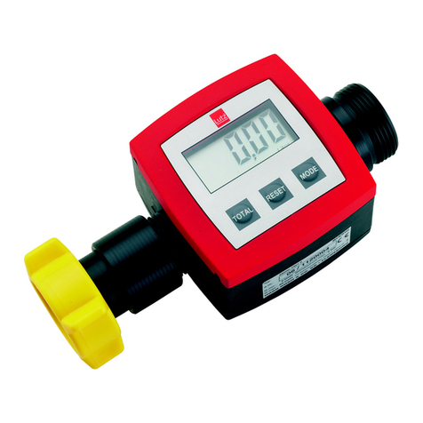
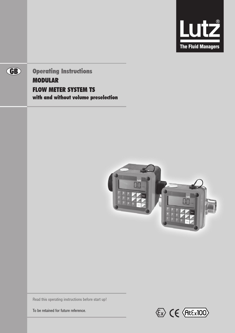
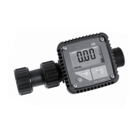
Lutz ST10 User manual

Translation of the
original instructions
BASIC FLOW METER
Type
ST10
SL10
LM10
UN10
VA10
HC10
HDO080
HDO120
HDO200
HDO250P
HDO250
HDO400
HDO500
Read this operating instructions before start up!
To be retained for future reference.
en

2
0698-601 Basic ow meter - 04/19
en
Table of Contents
A. General ............................................................................................................................................ 4
1. Concerning this manual.............................................................................................................. 4
1.1 Terms .................................................................................................................................. 4
1.2 Target groups...................................................................................................................... 4
1.3 Associated applicable documents....................................................................................... 4
1.4 Warnings and symbols ....................................................................................................... 5
1.5 Latest state.......................................................................................................................... 5
1.6 Copyright ............................................................................................................................ 5
2. Safety .................................................................................................................................. 6
2.1 General safety information................................................................................................. 6
3. Transport and storage................................................................................................................. 7
3.1 Transport............................................................................................................................. 7
3.2 Storage................................................................................................................................ 7
4. Year of construction .................................................................................................................... 7
5. Modular Flow Meter System TS................................................................................................... 8
6. Modular Flow Meter System HDO............................................................................................... 9
B. BasicowmeterTS......................................................................................................................... 10
1. Proper use ................................................................................................................................ 10
1.1 Application in explosion hazard areas .............................................................................. 10
1.2 Technical data ................................................................................................................... 11
1.3 Maximum pressure depending on temperature of the medium...................................... 12
1.4 Complete hose system...................................................................................................... 12
1.5 Pressure surges (water hammer) ..................................................................................... 12
1.6 Pressure drop.................................................................................................................... 13
1.7 Accuracyofmeasurementandowrate .......................................................................... 14
1.8 Liability.............................................................................................................................. 15
2. Prevention of obvious misapplication....................................................................................... 15
3. Installation ................................................................................................................................ 16
3.1 Connection for drum pump operation ............................................................................. 16
3.2 Connection to the piping system – Flange connection..................................................... 17
3.3 Valve connection............................................................................................................... 18
4. Maintenance and servicing....................................................................................................... 18
4.1 Cleaningthelterandcheckvalve................................................................................... 18
4.2 Dismantlingthebasicowmeter..................................................................................... 19

3
0698-601 Basic ow meter - 04/19
en
C. BasicowmeterHDO..................................................................................................................... 20
1. Proper use ................................................................................................................................ 20
1.1 Application in explosion hazard areas .............................................................................. 21
1.2 Technical data ................................................................................................................... 22
1.3 Liability.............................................................................................................................. 28
2. Installation ................................................................................................................................ 29
2.1 Electrical connection HDO080........................................................................................... 30
2.2 Drum pump connection.................................................................................................... 30
3. Operation ................................................................................................................................ 31
4. Disassembly and reassembly .................................................................................................... 31
4.1 BasicowmeterHDO250P............................................................................................... 31
4.1.1 Disassembly ............................................................................................................ 31
4.1.2 Reassembly ............................................................................................................. 32
4.2 BasicowmeterHDO120,HDO200,HDO250,HDO400andHDO500.............................. 33
4.2.1 Disassembly of wet ends ........................................................................................ 33
4.2.2 Assembly of wet ends.............................................................................................. 33
4.2.3 Reed switch board................................................................................................... 34
4.3 BasicowmeterHDO080 ................................................................................................. 35
4.3.1 Disassembly ............................................................................................................ 35
4.3.2 Reassembly ............................................................................................................. 35
D. Repairs .......................................................................................................................................... 36
E. Traceability...................................................................................................................................... 36
F. Waste disposal................................................................................................................................ 36
G. Annex .......................................................................................................................................... 37
1. Terminal assignment of cables and connectors........................................................................ 37
2. Trouble shooting ....................................................................................................................... 38
2.1 Fault report ....................................................................................................................... 38
2.2 Other faults....................................................................................................................... 40
SparepartslistbasicowmeterTS................................................................................................. 42-47
SparepartslistbasicowmeterHDO080............................................................................................ 48
SparepartslistbasicowmeterHDO250P..................................................................................... 49-50
SparepartslistbasicowmeterHDO120,200,250,400,500........................................................ 51-54
Declaration of Conformity .................................................................................................................... 55

4
0698-601 Basic ow meter - 04/19
en
A. General
1. Concerning this manual
This manual
• is part of this product
• is valid for all mentioned series
• describes the safe and proper use in all operating stages
1.1 Terms
User: Singlepersonororganisationwhoisusingtheproductse.g.customer,user,assistant
1.2 Target groups
Target group Task
User ►Retain these operating instructions at the product’s place of use for
future reference.
►Demandthestatoreadandobservetheseinstructionsandthe
additionalvaliddocuments,inparticularthesafetyinformationand
warnings.
►Observe additional regulations and instructions concerning the plant.
Qualiedpersonnel,installer ►Read,observeandfollowtheseinstructionsandtheadditionalvalid
documents,inparticularthesafetyinformationandwarnings.
Tab.1:Targetgroupsandtheirtasks
1.3 Associated applicable documents
Document Purpose
Operating instructions opera-
ting unit
Safeandproperuseoftheoperatingunit.Setupandcheckthefunctions
of the communication module.
Operating instructions relay
module
Safe and proper use of the relay module.
Operating instructions
communication module
Safe and proper use of the communication module.
Supplementary operating
instructions
for additional delivered components
Tab. 2: Associated applicable documents and purpose

5
0698-601 Basic ow meter - 04/19
en
1.4 Warnings and symbols
Warning Level of risk Consequences in case of
non-compliance
DANGER direct danger death or serious injury
WARNING possible direct danger death or serious injury
CAUTION possible dangerous situation light injury
NOTICE possible dangerous situation damage of property
Tab. 3: Warnings and consequences in case of non-compliance
Symbol Meaning
Safety information
► Complywithallmeasuresthataremarkedwithasafetysigntopreventinjuriesor
death.
iInformation / Recommendation
►What to do
→cross reference
3Requirement
Tab. 4: Symbols and meaning
1.5 Latest state
Pleasendthelateststateofthisoperatinginstructionunderwww.lutz-pumpen.de.
1.6 Copyright
The contents of these operating instructions and the images contained in them are subject to the copyright
protection of Lutz Pumpen GmbH.

6
0698-601 Basic ow meter - 04/19
en
2. Safety
The manufacturer will not be held responsible for any damages resulting from non-compliance of the
overalldocumentation,inparticularfordamagesincaseofnon-complianceoftheoperatinginstructions.
2.1 General safety information
Observe following regulations before accomplishing all activities.
Product safety
Thebasicowmeterisconstructedinconformitywiththestateoftheartandapprovedsafety-related
standards. Danger however can occur during use for life and health of the user or third parties or dama-
geofthebasicowmeterandothermaterialassets.Therefore:
• Operatethebasicowmeteronlyinatechnicallysoundstate,foritsproperuse,andconsciousof
safetyandhazardstakingintoaccounttheseinstructions.
• Ensurethattheseinstructionsandallassociatedapplicabledocumentsarecomplete,legible,and
stored in a place that personnel can access at all times.
• Refrainfromanymannerofworkingthatendangerspersonneloruninvolvedthirdparties.
• Inthecaseofasafety-relevantmalfunction,stoptheowmetersystemimmediatelyandenlista
responsible person to rectify the malfunction.
• Inadditiontotheoveralldocumentation,observethestatutoryorothersafetyandaccidentpreventi-
onregulations,aswellasthevalidstandardsandguidelinesoftherespectiveoperatingcountry.
Modications
Unlessthemanufacturerhasprovideditsconsentinwriting,themanufacturerisnotliableforinterven-
tionsperformedbytheuser(modications)ontheproduct,suchasconversion,alteration,newdesign,
etc.Modicationsnotagreedwiththemanufacturermayhavethefollowingeects,amongothers:
• Functional impairments on the appliance or plant
• Damage to the appliance and other property damage
• Environmental damage
• Personal injuries right through to death
Duties of the operator
Safety-conscious working
• Operatethebasicowmeteronlyinatechnicallysoundstate,foritsproperuse,andconsciousofsafety
andhazardstakingintoaccounttheseinstructions.
• Ensure observance and monitoring of:
- Proper use
- Statutory or other safety and accident prevention regulations
- Safety provisions in handling hazardous substances
- Valid standards and guidelines in the respective country of operation
• Provide protective equipment.

7
0698-601 Basic ow meter - 04/19
en
Personnel qualication
• Ensurethatpersonneltaskedwithworkonthebasicowmeterhavereadandunderstoodthese
instructionsandallassociatedapplicabledocuments,particularlysafety,maintenanceandservicing
information,beforetheystartwork.
• Clarifyresponsibilities,competenciesandmonitoringofthepersonnel.
• Ensurethatallworkiscarriedoutbytechnicalqualiedpersonnelonly:
- Assembly,servicing,maintenancework
- Workontheelectrics
Statutory warranty
• Duringtheguaranteeperiod,obtainthemanufacturer'spermissionformodications,maintenance
workoralteration.
• Use only original parts.
Duties of the personnel
• Observethenoticesonthebasicowmeterandmaintaintheminalegiblestate.
• Use protective equipment where necessary.
• Ensurethatthebasicowmeterisdisconnectedbeforeyoucarryoutassemblyandmaintenancework.
3. Transport and storage
3.1 Transport
Unpackingandcheckofconditionondelivery
►Unpackthebasicowmeteronreceiptandcheckfortransportdamages.
►Report transport damage to the manufacturer immediately.
►Checkthattheconsignmentiscompleteasordered.
3.2 Storage
NOTICE
Damage of property as a result of incorrect storage!
►Storebasicowmetercorrectly.
►StorebasicowmeterprotectedagainstweathereectsandUV-rays.
4. Year of construction
Theyearofconstructionoftheappliancecanbeseenontheeldfortheserialnumber.Hereareattached
totheserialnumberthebothlastdigitsoftheyearofconstruction,e.g.(-10fortheyear2010).

8
0698-601 Basic ow meter - 04/19
en
5. Modular Flow Meter System TS
Theowmeteroperatesaccordingtothepositivedisplacementprinciple.Inahousingttedwithinletand
outletisameasuringchamberthroughwhichtheuidisforcedtoowonitswaythroughthehousing.
Inthemeasuringchamber,anutatingdiscblockstheuid`sclearpath.Asitowsthroughthemeasuring
chamber,theuidpushesthenutatingdisctooneside.Itistheactionofdisplacingtheimpedimentwhich
produces the wobble movement of the disc and circular motion of the nutating disc shaft. By means of a
driver,amagnetwithseveralpolesissetintorotation,whichisabletoactivateamagneticallyswitched
contact through the lid of the housing. Every revolution of the nutating disc is assigned to a constant volume
andaxednumberofpulses,sopermittingtheelectonicevaluatingsystemtodeterminethevolumetric
owthroughthenumberofreceivedpulses.
For practically-orientated application, the ow meter system is made up of various modules:
ÀOperating unit
Electronicevaluatingunitwithtouchscreenforoperationoftheow
meter.
ÁProtection cap
Protectsthemodulesbasicowmeter,relaymoduleormainsunit
when the operating unit is decentrally installed.
Pulse converter
Ampliesthesignalsfromthebasicowmeter.Isrequiredifthe
signals need to be transmitted further than 5 m.
ÂRelay module
Switches the external electrical appliances such as pump motor and
solenoid valve and is controlled by the evaluating electronics of the
operating unit.
Mains unit
Supplies power to the operating unit when battery-powered operation
is not desired and when no relay module is needed.
Communication module
Istheinterfacetoothermanagement,controlorprocesscontrol
systemswithdierentinputsandoutputs.
à Basic ow meter
Housing and measuring chamber with all components for volumetric
measurement which come into contact with the transported medium.
The ow meter can be used in two dierent operating modes:
Manual mode: Forllingusingamanuallyoperatednozzle.The
part volume meter is reset to zero and the requi-
red volume is metered while the nozzle is being
operated.
Volume preset: Thepreselectedvolumeislledbypressingakey.
Volume preset is possible only when relay module
is connected.
Fig.1-Operatingunitandowmeter
Fig. 2 - Relay module and protection cap

9
0698-601 Basic ow meter - 04/19
en
Fig.3-Operatingunitandowmeter
Fig. 4 - Relay module and protection
cap
6. Modular Flow Meter System HDO
TheHDOseriesowmeterhasincorporatedtheovalgearprincipleintoitsdesign.Thishasprovento
beareliableandhighlyaccuratemethodofmeasuringow.Exceptionalrepeatabilityandhighaccuracy
overawiderangeofuidviscositiesandowratesarefeaturesoftheHDOseriesowmeterdesign.The
lowpressuredropandhighpressureratingmeanstheHDOseriesowmeterissuitableforbothgravity
and pump (in line) applications.
For practically-orientated application, the ow meter system is made up of various modules:
ÀOperating unit
Electronicevaluatingunitwithtouchscreenforoperationoftheow
meter.
ÁProtection cap
Protectsthemodulesbasicowmeter,relaymoduleormainsunit
when the operating unit is decentrally installed.
Pulse converter
Ampliesthesignalsfromthebasicowmeter.Isrequiredifthe
signals need to be transmitted further than 5 m.
ÂRelay module
Switches the external electrical appliances such as pump motor and
solenoid valve and is controlled by the evaluating electronics of the
operating unit.
Mains unit
Supplies power to the operating unit when battery-powered operation
is not desired and when no relay module is needed.
Communication module
Istheinterfacetoothermanagement,controlorprocesscontrol
systemswithdierentinputsandoutputs.
à Basic ow meter
Housing and measuring chamber with all components for volumetric
measurement which come into contact with the transported medium.
The ow meter can be used in two dierent operating modes:
Manual mode: Forllingusingamanuallyoperatednozzle.The
part volume meter is reset to zero and the requi-
red volume is metered while the nozzle is being
operated.
Volume preset: Thepreselectedvolumeislledbypressingakey.
Volume preset is possible only when relay module
is connected.

10
0698-601 Basic ow meter - 04/19
en
B. Basic ow meter TS
1. Proper use
Thebasicowmeterisusedformeasuringliquidvolumeswheregaugingmeteringisnotrequired.The
basicowmeterisprecalibratedfortheuseofwater.Themeasurementofotherpuremediaisalsopossible.
Todothis,adierentuser-speciccalibrationfactorisenteredattheoperatingunit.
NOTICE
These causes may impair the measurement result, damage the ow meter, or reduce its service life:
►stronglypulsatingow
►airbubblesintheow
►excessivelyloworhighowrate
►excessiveviscosityofthemeasureduid
►blowing through of compressed air.
1.1 Application in explosion hazard areas
!WARNING
Application in explosion hazard areas or the metering of ammable liquids can cause explosion
resulting in severe injury or death.
►Basicowmetersarenon-electricaloperatingappliancesnotrequiringocialapprovalwhenusedin
zone 1.
►ThebasicowmetersVA10,HC10,LM10andUN10correspondtothedirective2014/34/EU(groupII,
category2,forgasesandtemperatureclassT4).
►Thebasicowmetermayonlybeusedatatmosphericalconditionsof0.8barupto1.1baranda
temperaturerangeof-20°Cupto+40°C.Anapplicationisnotallowedinatmosphereswithammable
dust.
►ThetemperatureoftheliquidbeingpumpedislimitedfortypesLM10andUN10tomax.60°Candfor
types VA10 and HC10 to max. 80°C.
►Anequipotentialbondingmustbeestablishedbetweenbasicowmeter,pumptubeandhose-orpipe
line.
►Use only conductive pressure hoses or conductive pipes.
►Forapplicationswithadrumpumpthebasicowmetermustbemountedoutsideofthecontainer.
►Theadmissibleoperatingpressure(typesLM10andUN10-4bar,VA10andHC10-10bar)mustnot
be exceeded.
►In case another electronical device for analyzing is used than that provided by the manufacturer the
explosion protection regulations must be observed.
►Inordertoavoidresparkling,assemblyworksmustbecarriedoutbyqualiedpersonnelonly.
►Topreventcorrosionitmustbeensuredthatthebasicowmeterisresistanttotheliquidsbeing
transferred.
►Topreventanexplosivegasatmosphereinthebasicowmeteruseasolidhosesystem.

11
0698-601 Basic ow meter - 04/19
en
1.2 Technical data
Type ST10 SL10 LM10 UN10 VA10 HC10
Flow rate min. 10 l/min
max. 100 l/min*
min. 10 l/min
max. 100 l/min*
min. 10 l/min
max. 100 l/min*
min. 10 l/min
max. 100 l/min*
min. 10 l/min
max. 100 l/min
min. 10 l/min
max. 100 l/min
Temperature 60 °C 60 °C 60 °C 60 °C 80°C (60°C**) 80°C (60°C**)
Viscosity 2.000 mPas 2.000 mPas 2.000 mPas 2.000 mPas 5.000 mPas*** 5.000
mPas***
Operating
pressure
4 bar 4 bar 4 bar 4 bar 10 bar 10 bar
Accuracy ± 1% standard
≤1% with
adjustment
to application
conditions
± 1% standard
≤1% with
adjustment
to application
conditions
± 1% standard
≤1% with
adjustment
to application
conditions
± 1% standard
≤1% with
adjustment
to application
conditions
± 1% ± 1%
Inlet port G 2 male
threadtot
connector with
union nut
G 2 male
threadtot
connector with
union nut
G 2 male
threadtot
connector with
union nut
G 2 male
threadtot
connector with
union nut
G 1 1/4 G 1 1/4
Outlet port G 1 1/4 male
thread
G 1 1/4 male
thread
G 1 1/4 male
thread
G 1 1/4 male
thread
G 1 1/4 male
thread
G 1 1/4 male
thread
Weight 780 g 780 g 900 g 930 g 3300 g 3600 g
Materials:
Housing PPO PPO PPS PPS Stainless steel
(1.4581/1.4571)
Hastelloy C
(2.4610)
Measuring
chamber
PPO/PPS PPO/PPS LCP LCP Stainless steel
(1.4581/1.4571)
ETFE/PTFE****
Hastelloy C
(2.4610),
ETFE/PTFE
Seals FPM FPM FEP FEP FEP FEP
Magnet BaFe,PA,
Stainless steel
(1.4401)
PPS
encapsulated
BaFe,brass,
Stainless steel
PPS
encapsulated
PTFE
encapsulated
PTFE
encapsulated
Suitable for
Ex-applica-
tions
no no yes
conductive
yes
conductive
yes
conductive*****
yes
conductive
Order No. 0230-500 0230-510 0230-520 0230-530 0230-540 0230-550
* short-time 120 l/min.
** in explosion proof version
*** depending on the application
**** PVDFforVA10PURE,OrderNo.0230-330
PVDF/PEforVA10Ex-PURE,OrderNo.0230-331
*****not suitable for VA10 PURE
Description of material
PPO = Polyphenylene Oxide
FPM = Fluoro Elastomer
PA = Polyamide
PPS =PolyphenyleneSulde
BaFe = Barium-Ferrite
FEP =TetrauoroEthylene/HexauoroPropylene
LCP = Liquid Cristalline Polymere

12
0698-601 Basic ow meter - 04/19
en
1.3 Maximum pressure depending on temperature of the medium
Diagram 1 - Maximum pressure depending on temperature of the medium
1.4 Complete hose system
Beforeinitialstartingoftheowmeter,theentirepipingsystemmustbeslowlyventedfromthepump
throughtotheshutoelement(nozzle,solenoidvalveorsimilar).Duringoperation,caremustbetaken
toensurethatthecompletesystemislledwithliquid.
1.5 Pressure surges (water hammer)
Considerablepressureuctuationswithso-calledwaterhammercanbuildupinthesystemasaresultof
delays(disconnection/shuto)oraccelerationoftheowingliquidcolumnwhenusinglongdeliverylines
or when using solenoid valves with short opening and closing times.
!WARNING
The brief pressure peaks or surges due to water hammer can cause serious damage and destroy
the ow meter, pump or other components in the system! Danger by uncontrolled splashing liquid.
Dependingonthemediumconcerned,thiscanleadtocausticburns,explosionhazards,toxicvapours,
electricshocks,dangerofslippingandotherdangers!
Example:
A valve closing time of 20 ms can cause a pressure surge of up to 10 bar in a 10 metres long 1" pipe at a
owrateof50l/min.
Pressure surges can be prevented as follows:
• Usealargernominaldiameter(DN)toreducetheowspeedinthedeliveryline.
• Filling with step-by-step interruption (→OperatinginstructionsOperatingunit-Opoint).
• Usereliefvalvesandpressurelimitingvalvestoeliminateimpermissiblepressurepeaks.
TypeST10,SL10,LM10,UN10
TypeVA10,HC10

13
0698-601 Basic ow meter - 04/19
en
1.6 Pressure drop
Diagram2indicatesthepressuredroprelativetoow.Thesolidlineisapplicableforaqueousliquids
(ρ≈1kg/dm³,η≈1 mPas).
Incaseofmediawithdierentdensity(ρ≠1kg/dm³)thepressuredropvalueshavetobetakenfromthe
solid line in diagram 2 and multiplied by the density value of the liquid.
Media with a high dynamic viscosity (η>>1mPas)likehigh-densitymedia,causeahigherpressuredrop.
The limiting curve for permissible viscosity at ρ =1kg/dm³isdepictedindiagram2asadottedline.Ifthe
density ρ isgreaterthan1kg/dm³,thepressuredropsinthediagrammustbemultipliedbytheactual
density.
Diagram2-Pressuredropdependingonowvolume
TypeVA10,
HC10
TypeST10,
SL10,LM10,
UN10
specicdensityρ =1kg/dm³
Δp / (m wc)

14
0698-601 Basic ow meter - 04/19
en
1.7 Accuracy of measurement and ow rate
Inthefactorythemeteriscalibratedforaowrateof40l/min.Otherowratesaectthemeasurement
accuracyoftheowmeter(→diagram 3a and 3b).
Themeasurementaccuracywithregardtotheowcanbeimprovedintwoways:
1. Theowmeterispreciselycalibratedtotheowratewithregardtotheoperation(→operating inst-
ructions-operatingunit).Thisisthemostaccurate.However,itonlyworksataconstantowrate.
2. Themeasurementaccuracyovertheowraterangereactsdierentlydependingonthebasicow
meter type (→diagrams3aand3b).Ifthebasicowmetertypeisselectedontheoperatingunit(→
operatinginstructions-operatingunit),thentheaccuracyisautomaticallyimprovedforcertainow
rate ranges.
Q : Flow rate
Krel:Relative correction factor
out of diagram 3a or 3b
K1: Recent correction factor out
of main memory
K2: Newcorrectionfactor
Example for type ST10, SL10,
LM10, UN10:
Q= 20 l/min Krel=0,01
K1=1,028
K2= K1+ Krel
K2=1,028+0,01
K2=1,038
Example for type VA10:
Q= 20 l/min Krel=0,03
K1=3,37
K2= K1+ Krel
K2=3,37+0,03
K2=3,4
Diagram3b-Correctionfactordependingonowrate
Diagram3a-Correctionfactordependingonowrate
Relative correction factor
Relative fault in percent
Type VA10,
HC10
Relative correction factor
Relative fault in percent
Type ST10, SL10,
LM10, UN10

15
0698-601 Basic ow meter - 04/19
en
1.8 Liability
Iftheproductandsuppliedaccessoriesareusedforotherpurposesthantheintendedpurpose,itisthe
responsibilityoftheusertocheckthesuitabilityandadmissibility.Productusenotconrmedinwriting
by the manufacturer absolves the manufacturer of any liability.
Themanufacturerisnotliableforconsequencesofincorrecttreatment,use,maintenance,servicingand
operationoftheappliance,aswellasnormalwearandtear.Thesameappliesiffaultsarisefrominter-
ventionorcongurationsonthepartoftheusernotconrmedbythemanufacturer.
2. Prevention of obvious misapplication
!WARNING
The metering of non-compatible liquids damages the ow meter.
Splashing liquid or ying parts can cause injury.
►Checkbymeansofthematerialsindicatedinthetechnicaldataandaresistancetable(e.g.Lutzresis-
tancetable)whetherthebasicowmeterissuitableforthedeliveredliquid.
!WARNING
Exceeding the temperature range and the operating pressure causes damage to the basic ow
meter.
Splashing liquid or ying parts can cause injury.
►The ranges indicated in the technical data for temperature of liquid and operating pressure have to be
observed.

16
0698-601 Basic ow meter - 04/19
en
3. Installation
3.1 Connection for drum pump operation
Fig. 5 -
ConnectionfordrumpumpoperationtypeST10,SL10,LM10andUN10
Fig. 6 - Connection for drum pump operation type VA10
Mounting steps ow meter
type ST10, SL10, LM10 and
UN10:
1. Mountthecheckvalve
(option)andlterscreen
into the inlet (arrow). The
non-return valve may be
only installed together with
a strainer.
2. Insert the o-rings into the
collar bush. Wet the sealing
surfaces and o-rings with a
suitable lubricant.
3. Place the wing nut onto the
collar bush.
4. Screw the collar bush onto
the outlet of the pump tube.
5. Screw the wing nut with the
owmeter.
6. Screwthehosettingonto
theowmeteroutlet
G 1 1/4.
Mounting steps ow meter
type VA10:
1. Insert the seal into the wing
nut.
2. Screw the drum pump
connection onto the outlet of
the pump tube.
3. Insert the seal into the wing
nut and screw it with the
owmeter.
4. Screwthehosettingonto
theowmeteroutlet
G 1 1/4.

17
0698-601 Basic ow meter - 04/19
en
3.2 Connection to the piping system – Flange connection
NOTICE
For connecting the ow meter to the piping system, the following must be observed:
►Pipes,ttings,etc.mustbesuitablysupportedsothatadditionalweightandvibrationsarenottrans-
mittedtotheowmeter!
►Suction and discharge lines must always be connected without tension. The piping must be rerouted if
anosetcannotbecompensatedbyappropriatemeans!
Mounting steps ow meter
type ST10, SL10, LM10 and
UN10:
1. Mountthecheckvalve(opti-
on)andlterscreenintothe
inlet (arrow).
The non-return valve may be
only installed together with
a strainer.
2. Push the o-ring onto the
collar bush. Wet the sealing
surface and o-ring with a
suitable lubricant.
3. Place the wing nut onto the
collar bush and screw it with
theowmeter.
4. Insert the o-rings into the
screwsockets.
5. Screwthescrewsocketsonto
theowmeterandcollar
bush.
6. Insert the o-rings into the
screwsockets.
7. Mounttheange.
8. Screwontheangedbush.
Mounting steps ow meter
type VA10:
1. Placetheangeplateonto
the collar bush.
2. Insert the seal into the collar
bush.
3. Screw on the collar bush to
theowmeter.
Fig.7-FlangeconnectiontypeST10,SL10,LM10andUN10
Fig. 8 - Flange connection type VA10

18
0698-601 Basic ow meter - 04/19
en
3.3 Valve connection
Mounting steps:
1. Screw the double nipple
G 3/4 – G 1 1/4 into the
inlet and outlet side of the
solenoid valve.
2. Mount the hose connection
G 1 1/4 on both sides of the
hose.
3. Connect the hose with the
owmeteroutletandthe
solenoid valve inlet.
Noteowdirectionofthe
solenoid valve!
4. Screw the discharge bend
onto the outlet side of the
solenoid valve.
Fig. 9 - Valve connection
4. Maintenance and servicing
4.1 Cleaning the lter and check valve
Itisadvisabletoushandcleanthebasicowmeterafterhandlingaggressive,tacky,crystallizingorvery
contaminating liquids.
ProceduretypeST10,SL10,LM10andUN10:
1. Emptytheowmeter
2. Release the wing nut
3. Removethelterandcleanwithapaintbrushorblowthroughwithcompressedair
4. Pressinthecheckvalvemanuallyandblowthroughwithcompressedair

19
0698-601 Basic ow meter - 04/19
en
4.2 Dismantling the basic ow meter
Thebasicowmetercanbedismantledforcleaningthemeasuring
chamber or for troubleshooting.
!WARNING
The basic ow meter can still contain liquid during dismantling!
Incaseofaggressiveliquids,thiscanleadtoburns,poisoning,irri-
tationoftheskinetc.
Wear appropriate protective clothing when handling aggressive
liquids.Basicowmetermustbeemptiedbeforedismantling.Despite
ofpreviousemptying,residualliquidcanstillbeintheowmeter
housing during dismantling process. Therefore always remove the
cover Àupwards.
iWhendismantlingthebasicowmetersoftypeLM10,UN10,
VA10 and HC10 it is recommended to replace the o-ring Á. Wet
the sealing surface and o-ring with a suitable lubricant.
Basic ow meter ST10, SL10, LM10 and UN10 (→Fig. 10a):
1. Release the screws Åonthebottomsideoftheowmeter.
2. Remove the cover Àupwards.
3. Lift the measuring chamber Ãout of the basic body Ä.
4. Remove the o-ring Âof the measuring chamber.
5. Carefully open the measuring chamber.
Theassemblyiseectedinreverseorder.
When mounting the cover Àtakecareoftherightpositiontothe
basic body Ä.
Basic ow meter VA10 and HC10 (→Fig. 10b):
1. Release the screws Åonthebottomsideoftheowmeter.
2. Remove the cover Àupwards.
3. Remove the clamp Ã.
4. Lift the measuring chamber Âout of the basic body.
5. Carefully open the measuring chamber.
Theassemblyiseectedinreverseorder.
When mounting the cover Àtakecareoftherightpositiontothe
basic body Ä.
Fig. 10b -
Dismantlingthebasicowmeter
Fig. 10a -
Dismantlingthebasicowmeter

20
0698-601 Basic ow meter - 04/19
en
C. Basic ow meter HDO
1. Proper use
TheHDOseriesowmetersareusedformeasuringliquidvolumes.TheyareavailableinmaterialsPPS,
stainless steel or aluminium. Rotors are made of PPS or stainless steel.
!WARNING
Splashing liquid or ying parts can cause injury.
The metering of non-compatible liquids damages the ow meter.
►Checkbymeansofthematerialsindicatedinthetechnicaldataandaresistancetable(e.g.Lutzresistance
table)whetherthebasicowmeterissuitableforthedeliveredliquid.
Exceeding the temperature range and the operating pressure causes damage to the basic ow
meter.
►The ranges indicated in the technical data for temperature of liquid and operating pressure have to
be observed.
►Use only extensions and nozzles that are designed for use with this equipment.
►Seal all connections before you commission the machine.
!DANGER
Fire and explosion hazard due to delivered liquid!
Combustion hazard. Blast wave: Flying parts can kill.
→chapter 1.1 - Application in explosion hazard areas
NOTICE
Dirt or foreign matter exceeding a particle size of 0.25 mm will damage the ow meter.
Topreventdamagefromdirtorforeignmatter,werecommendaYorbaskettype60meshstrainerbe
installed as close as possible to the inlet side of the meter.
Note:Checkandcleanthestrainerregularly.Failuretokeepthestrainercleanwilldramaticallyeect
owmeterperformance.
NOTICE
Air purges can damage the ow meter.
►Whenstartingupslowlyllthesystemwithuid.
iThe reed switch can be used as a pulse transmitter for counters or PLC counter inputs provided by
customer. Bounce can cause inaccurate results. It is advised that a debounce circuit be used with high
speed counters.
This manual suits for next models
12
Table of contents
Other Lutz Measuring Instrument manuals
Popular Measuring Instrument manuals by other brands

Engineering Solutions
Engineering Solutions OMNIGUARD 5 owner's manual

Nikon
Nikon Forestry Pro user manual

Barnstead International
Barnstead International RD-1101 Operation manual and parts list

Photon Systems Instruments
Photon Systems Instruments FMT150 instruction manual

Tanita
Tanita DC-240 instruction manual

Extech Instruments
Extech Instruments LT510 user manual