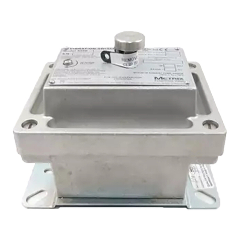
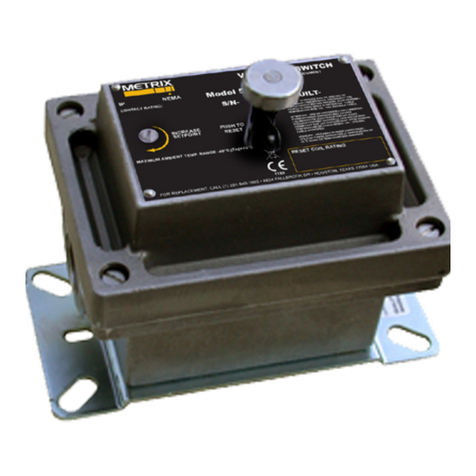
Metrix 440 User manual

440 & 450 ELECTRONIC VIBRATION SWITCHES
Installaon Manual
1. OVERVIEW
1.1 Introducon
The single setpoint models (SR) contain one
trip limit for shutdown. The oponal dual
setpoint models (DR) contain two indepen-
dent trip limits; one for alarm and one for
shutdown. Shutdown and alarm limits are
in engineering units of velocity. In addion,
a 4-20 mA output proporonal to vibraon
velocity is provided.
Models 440 and 450 use idencal design
and dier only in the enclosure. The model
440 is designed to be used in non-hazardous
or non-incendive hazardous locaon (Class
I, Division 2, Groups B, C, D, and NEMA
4X). The model 450 is designed to meet
explosion-proof requirements for Class
I, Division 1, Groups B, C, D installaons.
Unless otherwise noted, all discussions and
diagrams herein assume the model 440, but
apply equally to the model 450.
1.2 KeyCapabilies
• Shutdown and alarm sengs are based
on vibraon severity. The internal sen-
sor (unless the external sensor opon
has been specied (Ordering Opon
I=5 – see note in Secon 5.4) is a piezo-
electric crystal with built in microelec-
tronics to reduce noise sensivity. The
output signal is electronically integrat-
ed to measure and trip on velocity.
• Calibrated setpoint controls permit set-
point adjustment of vibraon velocity
levels up to full scale range. DR model
Doc# 90018-031 • REV L (April 2016)

Doc# 90018-031 • REV L (April 2016) Page 2 of 16
NOTE: Discrete outputs should be manually bypassed during
this procedure, parcularly if used to trip the machine. They will
change state aer the me delay, and should be externally jump-
ered or otherwise disabled to prevent nuisance trips.
Calibrated setpoint controls
enable operator to set specic
velocity alarm/shutdown levels.
Adjustable me delay of 2-15 seconds.
LED illuminates immediately when vibraon ex-
ceeds setpoint (but alarm or shutdown discrete
outputs will change state only aer me delay).
1.3UserInterface
KeyCapabilies(connued)
switches have dual setpoints – one for alarm and one for shutdown – that are indepen-
dently adjustable.
• 4-20 mA output provides a convenient interface for trending and displaying vibraon
amplitude in a programmable logic controller (PLC), SCADA system, data logger, or oth-
er instrumentaon. 4mA corresponds to no vibraon, and allows the user to disnguish
between no power to the switch (0mA) and a funconal switch but with no vibraon
present (4mA). 20mA corresponds to full scale vibraon amplitude.
• Discrete outputs used for alarming and shutdown can be selected from triac, solid-
state analog switch (FET), or electromechanical relays, but must be specied at me of
ordering. These outputs are independently congurable for open on alarm/shutdown
or close on alarm/shutdown .
• An adjustable (2-15 seconds) me delay is standard. This prevents false alarms/shut-
downs on high startup vibraons and also from non repeve transient events.
• Self-test and vericaon: An LED adjacent to each setpoint control illuminates the
instant the measured vibraon level exceeds the setpoint. The unit can be periodically
veried on line by turning the setpoint control down unl the LED comes on. This set-
ng is then compared with the vibraon amplitude measured via a portable vibraon
meter at the same locaon as the switch’s sensing element, providing a vericaon
check of the unit.

Doc# 90018-031 • REV L (April 2016) Page 3 of 16
NOTE: Turning either adjustment knob to the TEST posion reduces
the corresponding setpoint to its minimum allowable value, eec-
vely meaning that any vibraon will exceed the setpoint. Although
the LED will come on immediately, the discrete output will change
state only aer the duraon of the adjustable me delay has elapsed.
If the TEST posion is maintained for less than the duraon of the me delay,
the discrete output will not change state.
VDE approved terminal strip
accepts #12 AWG wire. All
hardware is capve.
Each discrete output is inde-
pendently eld congurable to
open on alarm (N.C.) or close
on alarm (N.O.)
3. SAFETY WARNINGS
CAUTION - SHOCK HAZARD 230/110 VOLTS
The terminal block inside the 440 is connected to AC power
(110 VAC or 230 VAC depending on model) except DC input
power models.
If adjustments to the device are being made with power applied, exer-
cise cauon to avoid contact with the terminal block screws by any part
of the body or electrically conducve tool.
EQUIPMENT OPERATION
Model 440 and 450 vibraon switches must be installed and operated
as described in this manual and in accordance with published datasheet
specicaons. Operaon outside these limits may adversely aect the
switch’s alarming and shutdown capabilies, resulng in damage to
machinery and property as well as jeopardizing personnel safety.
2. SPECIFICATIONS
Refer to product datasheet 1004730, available online at www.metrixvibraon.com.

Doc# 90018-031 • REV L (April 2016) Page 4 of 16
4. MECHANICAL INSTALLATION
4.1 Where to Mount the Switch
It is desirable to mount the electronic switch (or transducers for switches with external
transducer opon) on a bearing housing, since the forces generated by the rotang parts
through unbalance, misalignment, bearing wear, etc., are transmied to the machine’s cas-
ing through the bearings.
Most bearing housings are curved so it is necessary to aach a bracket with a at surface for
mounng the switch. If the machine has bolted end plates on the bearings or horizontally
split bearing housings, these bolts can be used to aach the bracket.
When bolt holes are not available or are not suitable, an alternave way is to weld an angle
iron bracket similar to that in the sketch, but oriented so as to straddle the bearing housing.
The best approach will typically be to mount a gusseted bracket, as shown below.
The guiding principle is to ensure that the bracket is suitably s such that machinery
vibraon is completely transmied through the bracket to the vibraon switch or sensor.
Problems can occur when the bracket is too compliant, and may allow bracket resonance
to amplify the actual machinery vibraon, resulng in false shutdowns or alarms. For many
applicaons, 3/8 Inch material (preferably steel) will be suitable.
4.2 SwitchSensiveAxis
The sensive vibraon “measuring” axis is perpendicular to the mounng base of the unit
(vibraon switch or transducer). Always mount the unit such that the desired vibraon of
the equipment being monitored will occur along this axis.
NOTE: Models using an external sensor will be sen-
sive along the sensor’s axis, not the switch’s axis.

Doc# 90018-031 • REV L (April 2016) Page 5 of 16
4.3 ChoosingMounngOrientaon
The vibraon switch can be mounted in the vercal or horizontal orientaon (or anything in
between) without a change in its sensivity. Ideally, the mounng orientaon will be chosen
by measuring the vibraon levels in both direcons with a vibraon meter and then select-
ing the direcon in which the highest vibraon occurs. This will typically be horizontal, since
most machine structures are less rigid horizontally than vercally.
4.4 NumberofPointsperMachine
Anywhere from one to four switches are used per machine (depending on how crical the
machine is to the process or how expensive it is), one on each end of the motor and one on
each end of the compressor, fan, pump or whatever is being driven. If there is a gear box in
between, one may be used here also.
It is quite common to use only one switch. In this case, it is best to mount on or near the
driven bearing. For example, if you have a motor and large fan with a bearing on each end
of the fan, the fan bearing on the motor side would be the driven bearing. It will usually see
the highest forces and have the highest vibraon level.
4.5 MounngatotherLocaons
When it is not possible to mount the switch directly on the bearing housing, the switch can
be located elsewhere, keeping in mind that it is usually machinery vibraon that is being
measured (not bracket, piping, or other vibraon). Do not mount the switch in locaons
where very lile machinery vibraon is transmied, as the switch will be less sensive to
damaging changes in machinery vibraon levels. Again, it is desirable to survey the machine
with a vibraon meter. If the level at the intended locaon is not aenuated by more than
about 50% relave to the levels directly on the bearing housing, it will probably be sasfac-
tory. However, alarm and shutdown sengs should then be reduced proporonately as well.
4.6 MounngSurface
Choose or fabricate a solid (rigid) surface (on the equipment being monitored) to mount
the vibraon switch or transducer. This will ensure transfer of the vibraon to the vibraon
transducer, while not introducing erroneous vibraons. In addion, the surface presented to
the base of the unit should be at. Fasten using sturdy hardware at all places provided.
4.7 TemperatureConsideraons
The switch is designed to dissipate internal heat by conducon through its base. Hence, it is
important to keep the mounng surface below the switch max temperature limit of 140°F. If
the equipment being monitored is going to exceed this limit, consideraon should be given
to either using one of the remote transducers, or thermally isolang the switch. To ensure
accurate switch performance, a warm up me of 5 minutes is recommended.
4.8 ElevaonConsideraons
The reduced atmospheric pressure at elevaons more than 2,000 meters (~6600 feet) above

Doc# 90018-031 • REV L (April 2016) Page 6 of 16
sea level does not allow heat to dissipate as readily as at lower elevaons, and the maximum
operang temperature must be de-rated by 2% per 300 meters. Thus, a switch installed at
an elevaon of 2,600 meters will have a maximum operang temperature 4% lower than
a switch installed between seal level and 2,000 meters. Refer to datasheet 1004730 for
complete specicaons.
4.9 Cable/Wiring
The method chosen to electrically connect to the switch or transducer should be mechani-
cally exible, to eliminate the measurement of vibraon of material not of interest (piping,
etc.), and provide a moisture barrier as well.
Although seal ght and other exible conduit have been used successfully, in areas of
extreme humidity or moisture it is recommended that a “SO” type cable together with a
suitable rain-ght CGB ng be used.
No stress should be possible on the wiring to the terminal block. If such protecon is not
provided by the conduit system, some form of stress relief must be installed where the wir-
ing exits the 440.
To reduce suscepbility to EMI/RFI, any signal-level wiring such as transducer, reset, lockout,
or 4-20 mA loop should ulize shielded cable in EMI-proof conduit, separate from any power
wiring. The signal-wiring conduit and power-wiring conduits can be connected at the switch
entry via a “T” ng.
4.10 Sealing
In installaons where temperature and humidity condions vary around the dew point, it is
important that the cover be evenly and rmly fastened down with the four screws provided
(model 440) or via the threaded cover (model 450).
Although the switch enclosures meet NEMA standards for water ghtness, this assumes the
cover is properly seated and wiring/conduit entrances use proper seals.
5. ELECTRICAL INSTALLATION
5.1 WiringtotheVibraonSwitch
See terminal numbering legends below. Refer also to the wiring diagrams of secon 8.
NOTE: Unless proper drains and/or poured seals are used,
conduit can allow moisture entry into the switch. Use good
installaon pracces that slope conduit away from the
switch, use drains (non-XP installaons only), and make
certain that cable jackets are not nicked or scued which might
allow moisture to wick into the switch via the conductors.

Doc# 90018-031 • REV L (April 2016) Page 7 of 16
5.1.1 Input Power
Connect a grounding wire to the grounding screw provided in the switch. This is impor-
tant for safety as well as noise. For AC powered units, power only with the voltage level
indicated on the inner cover label. Orientaon of AC power to terminals 1 and 2 is not
important. For DC powered units, connect +24V to Pin 1 and Ground to Pin 2.
5.1.2 Shutdown Circuit
The internal shutdown switch circuit is designed to be wired in series with the external
shutdown circuit i.e.; motor starter, relay, contactor, etc.
5.1.3 RemoteReset
Shielded wire is required. To avoid creang ground loops, the N.C. remote switch contacts
should be electrically isolated from other circuits or grounds. NOTE: Remote reset is dis-
abled if pushbuon reset opon is selected.
Lockout(Oponal)
Terminal 7 will be labeled “Lockout”. Shielded wire is recommended. To avoid the possibility
of ground loops, the remote N.O. lockout switch contacts should be electrically isolated from
other external circuitry or grounds.
5.1.4 4-20mAAnalogOutput
To avoid the possibility of ground loops, the 4-20 mA remote meter terminals should be
electrically isolated from external grounds. Shielded wire is recommended to protect
against damage due to long wire runs and the possibility of high induced voltage spikes
from storms, etc. The 4-20 mA output is self powered and therefore requires no external
power source.
5.1.5 AlarmCircuits
The internal single pole solid state switch between terminals 13 and 14 is designed to be
wired in series with the external alarm circuit i.e.; annunciator, lamp, relay, etc.
5.2 FunconalDescriponandInstallaonConsideraons
5.2.1 Alarm or Shutdown
5.2.2 UnitswithTriacOutputs(orderingoponsDand/orE=1)
The triacs used in model 440/450 vibraon switches carry medium power rangs and are
useful in controlling relays, contactors, and most motor starters directly. Maximum noise
immunity is obtained when used in the open on alarm (N.C.) mode. Consult Metrix prod-
uct datasheet 1004730 for comprehensive specicaons pertaining to triac outputs.
5.2.3 UnitswithAnalogSwitch(FET)Outputs(orderingoponsDand/orE=2)
For light loads such as computers or PLCs, the analog switch output is easier to interface
since it has virtually no leakage current. The analog switch does not require the 50 mA
holding current of a triac and operates equally well with AC or DC. Consult Metrix product
datasheet 1004730 for comprehensive specicaons pertaining to FET outputs.
NOTE: DR models have both Shutdown and Alarm
circuit present; SR models have only Shutdown circuit.

Doc# 90018-031 • REV L (April 2016) Page 8 of 16
5.2.4 UnitswithElectromechanicalRelayOutputs(orderingoponsDand/orE=4)
Electromechanical relays are also available and represent the most exible type of output.
They are a good choice for a variety of applicaons. Consult Metrix product datasheet
1004730 for comprehensive specicaons pertaining to relay outputs.
5.2.5 Open/CloseonAlarm
The alarm and shutdown triacs (or analog switches) are independently eld seable
for N.O. (close on alarm) or N.C. (open on alarm). The switches are accessible with a
non-conducve screwdriver via the inner side panels. Open on alarm is recommended in
installaons where triac lines are likely to be noisy, i.e.: large transient voltage spikes due to
unsuppressed relay, solenoid or other inducve loads.
5.2.6 AutoResetMode
In this mode, alarm and shutdown switches are automacally reset to the non-alarm/non-
shutdown condion when the vibraon level falls below the set point.
5.2.7 Latch Mode
In this mode, alarm and shutdown switches remain “latched” in alarm (shutdown) condi-
on when the vibraon level exceeds the set point for the duraon of the me delay. The
unit is in this condion when the reset terminal is connected to common.
RemoteResetMode
When wired in this mode, the alarm and shutdown switches latch in “trip”, but can be reset
to the “non-alarm/non-shutdown” mode by momentarily interrupng the connecon from
terminal Reset to Common. This can be accomplished with a normally closed momentary
switch. The switch contacts should be isolated from other circuits, potenals or grounds.
5.2.8 20-SecondLockout(oponal)
With this opon, the shutdown and/or alarm triacs will not be permied to actuate for 20
seconds aer Lock out is connected to Common.
5.2.9 4-20 mA Output
This loop supplies its own 24Vdc power and provides a 4-20 mA output current propor-
onal to vibraon.
Most switches are supplied with ordering opon B=2 (absolute 4-20mA output reference)
where 4mA = no vibraon and 20mA = full scale vibraon (refer to product datasheet
1004730 for full scale range opons). A small number of older switches may use a B op-
on other than 2, designang an analog output that is proporonal to the setpoint rather
than the full-scale range. Consult the factory for addional informaon.
5.3 SpecialConsideraons
NOTE: Remote reset is disabled if
pushbuon reset opon is selected.
NOTE: Do NOT connect the 4-20mA output to an exter-
nal source of loop power as this may damage the switch.

Doc# 90018-031 • REV L (April 2016) Page 9 of 16
5.3.1 LightLoads
The solid state triacs used in the standard 440 series are a special high transient immunity,
medium power type. O state leakage is 1 mA max and should not create any problems,
even when interfaced with a load as light as a programmable controller.
Minimum load required to keep the triac on is 20 mA typical and 50 mA max due to the
“holding current” specicaons. If the load is less than this, a resistor may have to be
placed in parallel with the load, i.e.; for 115 VAC light load (50 mA or less) a 2K-ohm 10
wa power resistor is recommended.
5.3.2 D.C.Loadswithtriacs
Although most applicaons use AC input power and AC on the triac outputs (alarm and
shutdown), these triacs may be used in DC applicaons providing minimum loading re-
quirements are met. When DC is used, a triac will automacally latch in the “on” condion
aer trip, thus only “close on alarm” (N.O.) can be used. To reset an external reset switch,
the rest switch must be wired in series with the load. To avoid large voltage drops during
DC operaon, the triac should be connected as follows:
Shutdown: Term 4 POS Alarm: Term 14 POS
Term 3 NEG Term 13 NEG
5.3.3 170mAAnalogSwitchOpon
The special condions of secons 5.3.1 and 5.3.2 do not apply. However, maximum cur-
rent is limited to 170 mA.
5.4 FunconalCircuitBlockDescripon
An internal transducer module consisng of a crystal assembly and integral charge amplier
senses vibraon. Thus, the electrical output of the transducer is a well-buered (low imped-
ance) signal directly proporonal to vibratory acceleraon levels (g) at the switch.
The raw acceleraon signal goes to a custom hybrid circuit that integrates the signal and pro-
vides an AC signal proporonal to vibratory velocity instead of acceleraon. This signal is then
routed through an amplier, the gain of which is controlled by the shutdown setpoint.
Next, the signal is processed through a true RMS-to-DC stage and compared against a preset
internal voltage reference. If the signal level is higher than reference, the shutdown LED is
illuminated.
If the voltage level stays above the reference for the duraon of the me delay, an output
trip occurs and the shutdown solid-state relay will trip.
Alarm trip is derived in much the same manner, branching from the output of the RMS-to-
DC stage. Likewise, the DC output is directed to the voltage-to-current hybrid.
NOTE: Models using an external (Ordering Opon I=5)
sensor do not have an internal accelerometer and will
measure vibraon at the sensor locaon, not the switch
locaon. Refer to Metrix product datasheet 1004730 for a list
of ordering opons characterizing external transducers.

Doc# 90018-031 • REV L (April 2016) Page 10 of 16
6. CONTROL SETTINGS
6.1 SengTripPoints
The Model 440DR provides two setpoints: one for alarm and one for shutdown.
The rst alarm is normally set at a vibraon alarm level to provide early warning that the
condion of the machine is deteriorang. If the machine condion connues to deteriorate,
the shutdown setpoint provides protecon against catastrophic failure. The shutdown and
alarm setpoints are set directly in inches/seconds or mm/sec.
The Warning Level Guide below indicates recommended starng points for vibraon warning
levels, dened as levels at which abnormal wear is occurring. Vibraon analysis by compe-
tent machinery diagnosc personnel is recommended when a warning alarm level has been
reached. Dierent warning levels are given for dierent types of machinery.
NOTE: SR models provide only
one setpoint (shutdown).
NOTE: The ranges below are typical. Each machine
will have its own acceptable levels of vibraon,
depending on how it is loaded, the parcular instal-
laon, and the tolerances of the machine itself. The chart
below is a guideline and does relieve the user of respon-
sibility for determining their own acceptable alarm and
shutdown levels for the equipment at hand.
WarningLevelGuide
6.2 SengofTimeDelay
An important feature of Model 440/450 switches is the built-in me delay. This prevents
triggering of the alarm or shutdown funcons from transient increases in vibraon levels. It
also avoids shutdown due to transitory vibraons occurring during start-up.
The me delay is adjustable. The factory default seng is three (3) seconds unless specied
otherwise.

Doc# 90018-031 • REV L (April 2016) Page 11 of 16
The me that the vibraon amplitude must persist above a setpoint before the discrete out-
put changes state is individually adjustable for shutdown and alarm from 2 to 15 seconds.
To readjust the me delay, turn the shutdown setpoint (or alarm setpoint for alarm me
delay) knob CCW unl the LED illuminates. The me from this point to relay actuaon is
the me delay. Change the me delay via a nylon non-conducve screwdriver. Set CW to
increase me delay (one complete turn is approximately 0.5 seconds). Then, recheck and
readjust unl the desired me delay is achieved.
6.3 TestMode
The TEST posion of both shutdown and alarm setpoint adjustment knobs is used to test
the switch funcons without the need for vibraon. When the shutdown knob is turned to
TEST, the shutdown LED should illuminate and the discrete output should change state aer
the delay me (see secon 6.2) has elapsed. The alarm TEST posion (available only on DR
model switches) funcons in similar fashion, but has no eect on the 4-20 mA output.
6.4 AscertainingCurrentVibraonLevels
When the 4-20mA output is not being used with a strip chart recorder, PLC, or other log-
ging device, you can place an ammeter across this output and the current measured. 4mA
corresponds to zero vibraon and 20mA corresponds to full scale vibraon. Readings in
between these two extremes can be ascertained by scaling proporonately from 0% (4mA)
to 100% (20mA). Alternavely, the LED indicators for alarm (DR model only) or shutdown
(both SR and DR models) can be used. Since these LEDs acvate instantaneously (i.e., before
the adjustable me delay of secon 6.2), they can be used in a momentary fashion to check
the machine’s actual vibraon level. Slowly decrease the setpoint by turning the setpoint
adjustment knob counter-clockwise unl the corresponding LED illuminates. Note this set-
ng and quickly return the knob to its original seng (before me delay runs out). The level
at which the LED illuminates corresponds to the actual vibraon level.
NOTE: If the shutdown or alarm knob is moved
to the TEST posion but then returned to a nor-
mal seng before the duraon of the me delay
has elapsed, the LED will come on but the discrete
output (triac, FET, or relay) will not change state.
NOTE: For DR model switches where both shut-
down and alarm setpoints will be available, it is
recommended that the alarm setpoint adjustment
be used for this procedure instead of the shutdown
setpoint, to prevent an inadvertent machine trip.

Doc# 90018-031 • REV L (April 2016) Page 12 of 16
7. OUTLINE & DIMENSIONS
440 Model
Units: mm [in]

Doc# 90018-031 • REV L (April 2016) Page 13 of 16
450 Model
Units: mm [in]

Doc# 90018-031 • REV L (April 2016) Page 14 of 16
8. WIRING DIAGRAMS
These diagrams depict connecons for models with all opons present. Not all connecons
may be available on your specic switch(es), depending on whether oponal features were
specied at me of ordering.

Doc# 90018-031 • REV L (April 2016) Page 15 of 16

Doc# 90018-031 • REV L (April 2016) Page 16 of 16
info@metrixvibraon.com
www.metrixvibraon.com
8824 Fallbrook Dr. Houston, TX 77064, USA
Tel: 1.281.940.1802 • Fax: 1.713.559.9421
Aer Hours (CST) Technical Assistance: 1.713.452.9703
This electronic equipment was manufactured according to high quality stan-
dards to ensure safe and reliable operaon when used as intended. Due to its
nature, this equipment may contain small quanes of substances known to be
hazardous to the environment or to human health if released into the environ-
ment. For this reason, Waste Electrical and Electronic Equipment (commonly
known as WEEE) should never be disposed of in the public waste stream. The
“Crossed-Out Waste Bin” label axed to this product is a reminder to dispose of this product
in accordance with local WEEE regulaons. If you have quesons about the disposal pro-
cess, please contact Metrix Customer Services.
ENVIRONMENTAL INFORMATION
This manual suits for next models
1
Table of contents
Other Metrix Switch manuals
