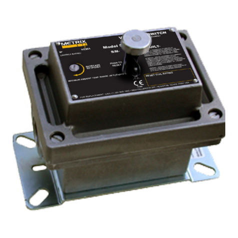
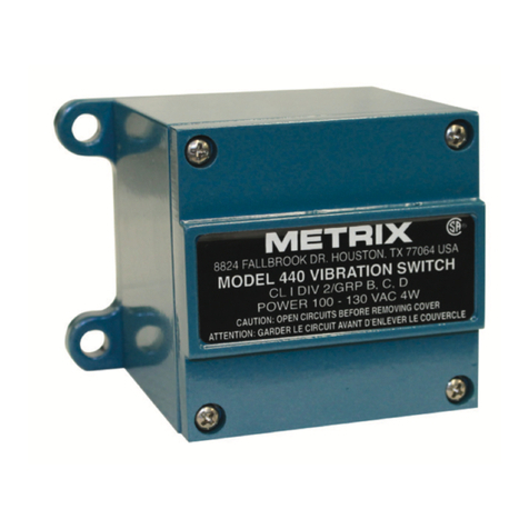
Metrix 5550 User manual

5.130
4.230
5.563
4.250
SET POINT
ADJUSTMENT
SCREW
RESET PUSH
BUTTON
1x M20
3.688
2.313
4X 10-32 UNF
REV.
ECO NO
DESCRIPTION
BY
DATE
A
Initial Release
RAP
6/11/2020
VENDOR
MODEL NUMBER
Metrix Instrument Co.
5550-411-04
Metrix Instrument Co.
5550-311-04
Vibration Switch
SHEET 1 OF 1
REV
DRAWING NUMBER:
DESCRIPTION:
MAT'L #:
MAT'L:
DESCRIPTION:
CHECKED BY:
MODELED BY:
PURCHASED
3003 Alloy
3/22/2011
KLB
1:4
Metrix 5550-411-04 Single Pole, Double Throw
Switch Vibration ATEX SPDT
A
028-000-481
THIS DRAWING IS THE SOLE PROPERTY OF
GREAT WESTERN MFG. CO. INC.
AND IS PROTECTED UNDER ALL APPLICABLE
COPYRIGHT LAWS. THIS DRAWING MAY NOT BE
REPRODUCED WITHOUT PRIOR WRITTEN PERMISSION.
WE RESERVE THE RIGHT TO MAKE IMPROVMENTS OR
CHANGES. THIS DRAWING IS LOANED SUBJECT
TO RETURN ON DEMAND.
UNLESS OTHERWISE NOTED DIMS. ARE IN INCHES
AND TOLERANCES ARE AS FOLLOWS:
MACHINING
.003 WELDING
.060 ANGLES
1
FORMING
.015 ASSEMBLY
.060
DATE:
DATE:
A
SIZE
SCALE:
6.197

4
Switches
Tel: 713-461-2131 • 800-638-7494 (US) • Fax: 713-461-8223
Vibralert®Mechanical Switch
Model 5550
The Model 5550 vibration switch is designed to meet all requirements for me-
chanical switches in a single, affordable package. This unit provides economical vibra-
tion protection for low to medium speed machinery. An inertia sensitive mechanism
activates an snap-action switch with SPDT output contacts if the vibration exceeds
an adjustable setpoint. The Model 5550 contacts can be used to activate an
alarm or initiate equipment shutdown. The housing is weatherproof with an op-
tional hazardous area rating. Electrical (remote) reset with start-up time delay
and a second set of SPDT output contacts to accomodate DPDT needs (e.g.
separate trip and trip light circuits) are available.
Features
•Meets all requirements
for mechanical switches
in one package
•Weatherproof and optional
hazard area rating
•Local and optional remote
reset with startup delay
•SPDT or (2)SPDT switch
output contacts
Applications
•Heat Exchanger Fans
•Cooling Tower Fans
•Recip Engines
•Recip Compressors
NOTE:
(2) SPDT
contacts
and
reset coil
optional
User Wiring Diagrams
(2) SPDT CONTACTSSPDT CONTACTS
Typical Installation Diagrams
COOLING
TOWER
FAN
GEARBOX
VIBRATION SWITCH
LOCATION
MOTOR
SWITCH
LOCATION
MOTOR
HEAT
EXCHANGER
FAN
Application Note:
For an upgrade to velocity (ips or mm/s)
monitoring or for dual limits (i.e. separate
alarm and trip setpoints), see SW Series
electronic switches.
BASIC MODEL
NUMBER
5550
APPLICATION TIPS
-Lowest cost vibration protection;
-Baseplates available to accomodate most previous
Metrix or competitor’s switch models for easy retrofit.
-Watertight & optional hazardous area rated enclosure
-Options for built-in start up trip delay and/or remote reset.
4.7

4
Switches
Tel: 713-461-2131 • 800-638-7494 (US) • Fax: 713-461-8223
Model 5550 Weight & Dimensions
Function: Armature mechanism trips
on high vibration and operates snap action
switch(es).
Vibration Range: See How to Select “C”
Frequency Range: 0 to 3600 RPM
Set Point Adjust: 0 to 100% of range.
External set point adjustment.
Reset: Local reset, plus optional remote
reset electrical coil. See How to Select.
Start Delay: Applying reset coil voltage at
start up holds mechanism from tripping for
20-30 seconds, after which the switch is
automatically activated. Requires electric
reset option (D¹0).
Temperature Limit: -40° to +70°C
(-40° to +158° F)
Enclosure: Cast Aluminum
Environmental Rating: NEMA 4, IP 65 & CE
mark
Switch Contact(s) Rating: 15 amps,
125, or 480 vac; 1/8 hp, 125 vac;
1/4 hp, 250 vac; 1/2 amp, 125 vdc;
1/4 amp, 250 vdc.
Hazard Rating: See How to Select “A”
Weight: 1.8 kg (4.0 lbs.)
Specifications
How To Select...
MODEL A B C D E F
5550 - -
AHazard Area Rating
0= None
1= UL, cUL Explosion Proof
Class I, Groups C & D, Div 1
Class II, Groups E,F & G, Div 1
2= UL, cUL Explosion Proof
Class I, Groups B, C & D, Div 1
Class II, Groups E,F & G, Div 1
3= CENELEC Flameproof
EEx d IIB T6
4= CENELEC Flameproof
EEx d IIB+H2T6
BContacts
1= SPDT
2= (2) SPDT (use for
DPDT too)
Standard
5550 - 0 1 1 - 0 1
CFull Scale Vibration Range
1= 5 g
2= 2 g
3= 10 g
DReset Coil & Start Up Delay
0= None
1= 115 VAC
2= 230 VAC
3= 24 VDC
4= 115 VDC
EWiring Entry/Mounting Plate
(See Chart below for E)
1 = 3/4” NPT/Metrix 5173 or 5175
2 = 3/4” NPT/Metrix 5097; VS-2-EX; 366
3 = 3/4” NPT/Metrix 5078; 365
4*= M20 x 1.5/Metrix 5097; VS-2-EX; 366
(L) (W) (A) (B)
E = 1
E = 2; 4
E = 3
165 mm [6.50]
152 mm [6.00]
165 mm [6.50]
38 mm [3.25]
121 mm [4.75]
121 mm [4.75]
141 mm [5.56]
118 mm [4.63]
136 mm [5.37]
*FOR E=4, A ≠1 OR 2
108 mm [4.25]
142 mm [5.60]
135 mm [5.33]
113 mm [4.43]
48 mm [1.88]
4X 19.0mm X 9.5 mm
(.750 x .375)
Vibralert®Mechanical Switch
Model 5550
4.8
Internal Mechanism
FEnvironmental Rating
1= NEMA 4X
59 mm [2.33]
79 mm [3.12]
92 mm [3.62]
CHART FOR HOW TO
SELECT “E”

!1711 Townhurst DR., Houston, TX 77043-2899
Tel: 713-461-2131 Fax: 713-461-8223
e-mail: [email protected]
M8905 05/02 ERO 8848
INSTALLATION OF METRIX MODEL 5550
MECHANICAL VIBRATION SWITCH
MW
SERIES
Thisbulletin should beused byexperienced personnel asa guide
to the installation of the Model 5550 vibration switch. Selection
or installation of equipment should always be accompanied by
competent technical assistance. We encourage you to contact
Metrix Instrument Co. or its local representative if further informa-
tion is required.
IMPORTANT: BEFORE PROCEEDING TO INSTALLAND WIRE
THE UNIT, READ AND THOROUGHLY UNDERSTAND THESE
INSTRUCTIONS.
THE SWITCH MODEL NUMBER SHOULD BE CHECKED TO
CONFIRM THAT YOU HAVE THE CORRECT HAZARDOUS
AREA RATING FOR YOURAPPLICATION. SEE HOW TO OR-
DER INFORMATION. "A"
INSTALLATION:
1) The sensitive axis of the vibration switch is perpendicular to
the mounting base. The preferred mounting is with the sensitive
axis in the horizontal plane, since most machines vibrate more in
that plane. Mount the switch solidly to the frame of the machine.
2) Remove the cover and wire the switch(es) into the alarm or
shutdown circuit. Do not exceed switch contact ratings listed in
the specifications. Keep field wiring away from the moving
part of the mechanism.
3) Observe all local electrical codes.
SETPOINT ADJUSTMENT:
1)Thevibrationsetpoint adjustment isaccessibleexternally. Turn-
ing the setpoint adjustment clockwise (CW) increases the vibra-
tion setpoint.
2) When the switch is shipped from the factory, the setpoint ad-
justment is set to 2g when installed in the vertical position and 1g
when installed in the horizontal position (with reference to the
setpoint adjustment shaft).
3)Tocheck factorycalibration, place unmounted unit in your hand
and rotate per diagram D. The switch(es) should activate at dead
bottom position. If necessary, adjust setpoint using the setpoint
adjustment screw.
4) To preset switch at other than factory setpoint, start with step
three (3) and then rotate adjustment screw 1/8 turn per g until
you reach the required set point.
5) To adjust setpoint when installed on the machine, mount and
wire the unit. Reset the switch by depressing the reset plunger
andstart the machine. Whenthe machinehas reached fullspeed,
slowly turn the vibration setpoint adjustment counter-clockwise
until the switch trips. Then turn the adjustment clockwise a small
amount (approx. 1/8 turn). Reset the switch and restart the ma-
chine to determine whether the machine starting roughness will
cause the switch to trip, in which case it may be necessary to
increase the setpoint.
ELECTRICAL RESET AND STARTUP LOCKOUT:
The optional electrical reset circuit consists of an electrical sole-
noid in series with a thermistor. If the rated voltage is continu-
ously applied to the reset circuit at machine startup, the reset
solenoid energizes for a fixed time interval (approx. 30 sec.), af-
ter which time the solenoid is automatically de-energized by the
thermistor. This action provides a trip lockout during machine
startup roughness. The voltage must be removed from the reset
circuit when the machine is stopped to allow the thermistor to
cool off. The switch mechanism can then be reset electrically by
a momentary application of the reset voltage or it can be reset
manually.
NOTE: If the machine is restarted immediately after a shutdown,
the lockout period will be shortened because the thermistor will
be hot. An increase in the ambient temperature will also shorten
the lockout period.
ENGINE COMPRESSOR
COOLING TOWER FAN
GEARBOX
VIBRATION SWITCH
LOCATION
SWITCH
LOCATIONS
MOTOR
SWITCH
LOCATION
MOTOR
TYPICALINSTALLATIONS
HEAT EXCHANGER FAN
COMPRESSOR
1 g
SETPOINT
SWITCH
ACTIVATED
2 g
SETPOINT DIAGRAM D
SHAFT

Page 2 M8905
SPECIFICATIONS
Function: Armature mechanism trips on high vi-
bration and operates snap action switch(es).
Amplitude Range: See How to Order. "C"
Frequency Range: 0 to 3600 RPM.
Setpoint Adjust: 0 to 100% of range.
External setpoint adjustment.
Reset: Local reset, plus optional remote reset
electrical coil. See How to Order. "D"
Start Delay: Applying reset coil voltage at start
up holds mechanism from tripping for 20-30 sec-
onds, after which the switch is active. Requires
electric reset option.
Temperature Range: -40°C to 70°C
Enclosure: High strength copper-free (4/10 of
1% max) Aluminum alloy.
Environmental Rating: NEMA 4, IP 65 & CE
Mark (NEMA 4X OPTIONAL)
Switch Contact(s) Rating:15amps,125, or 480
Vac; 1/8 hp, 125 Vac; 1/4 hp, 250 Vac; 1/2 amp,
125 Vdc; 1/4 amp, 250 Vdc.
Hazard Rating: See How to Order. "A"
Weight: 2.1 kg (4.5 lbs.)
WIRING DIAGRAM
DPDT CONTACTS AND RESET COIL OPTIONAL
SPDT DPDT
DIMENSIONS IN mm (inches)
*Note: When option A1 or A2 is specified,
options E4, E5, E6 and E8 are not allowed.
L(+) RESET COIL
N(-) RESET COIL
GRN CASE
L(+) RESET COIL
N(-) RESET COIL
GRN CASE
(L) (W) (A) (B)
165mm [6.50] 83mm [3.25] 141mm [5.56] 59mm [2.33]
121mm [4.75] 152mm [6.00] 79mm [3.12] 118mm [4.63]
165mm [6.50] 121mm [4.75] 136mm [5.37] 92mm [3.62]
114mm [4.50] 127mm [5.00] 71mm [2.80] 108mm [4.25]
E=1, 6
E=2, 4, 5
E=3, 8
E=7
MODEL A B C D E F
5550 - """ -"""
How To Order...
A" Hazard Area Rating
0= None
1= UL, cUL Explosion Proof, Class I, Groups C & D, Div 1
Class II, Groups E, F & G, Div 1
2= UL, cUL Explosion Proof, Class I, Groups B, C & D, Div 1
Class II, Groups E, F & G, Div 1
3= CENELEC Flameproof, EEx d IIB T6 DEMKO 02 ATEX 0212409
4= CENELEC Flameproof, EEx d IIB+H2T6 CE 0600 II 2 GD
B" Contacts
1= SPDT 2= DPDT
C" Full Scale Range
1= 5 g 2= 2 g 3= 10 g
D" Reset Coil & Start Up Delay
0= None 1= 115 VAC 2= 230 VAC 3= 24 VDC 4= 115 VDC
E" Wiring Entry/Mounting Plate (retrofit)
1= 3/4” NPT/Metrix 5173 or 5175
2= 3/4” NPT/Metrix 5097; VS-2-EX; 366
3= 3/4” NPT/Metrix 5078; 365
4= M20 x 1.5/Metrix 5097; VS-2-EX; 366
5= Same as option 4 above with epoxy coated mounting plate
6= M20 X 1.5 / METRIX 5173 or 5175
7= 3/4” NPT / PMC/BETA 440
8= M20 X 1.5 / METRIX 5078; 365
F" Environmental Rating
0 (or blank) = NEMA 4, IP 65, CE
1 = NEMA 4X, IP 65, CE
Example
5550 - 0 1 1 - 0 1 0
*
*
*
*
*
Tested for Compliance with the
applicable EC Electromagnetic
Compatibility Requirements
*
Mounting Plate for
E=1, 6 Shown

Other manuals for 5550
2
Table of contents
Other Metrix Switch manuals


