Metrodata LV2000 User manual

Metrodata Ltd
Fortune House
Crabtree Office Village
Eversley Way
Egham
Surrey TW20 8RY
United Kingdom
tel: +44 (0) 1784 744700
fax:+44 (0) 1784 744730
website: www.metrodata.co.uk
Metrodata LV2000
Ethernet LAN to EIA-644 LVDS
Converter Installation Guide
LV 2000
www.metrodata.co.uk

INTRODUCTION
1
1 INTRODUCTION
1. 1 About the LV2000
The Metrodata LV2000 is used to extend a LAN segment over an LVDS network connection,
such as a satellite modem across a satellite link to a remote site. LAN data is adapted to a
synchronous format using HDLC as a transport mechanism. Frame integrity is ensured by
appending a 16 bit FCS to the LAN packet before transmission. At the far end, incoming
packet integrity is checked using the 16 bit FCS, which is stripped for good packets before
forwarding to the LAN port. If the FCS is incorrect, the packet is discarded.
The LV2000 has an auto-negotiating 10/100BaseT Ethernet port and an EIA-644 LVDS DTE
port for LVDS connection mounted on the rear panel of the unit. The maximum speed of the
LVDS DTE port is 52 Mbps.
LV2000 units are used in pairs or in conjunction with other Metrodata Extension products,
such as the WAN-in-a CAN (WC1000) or the LH1000.
Figure 1. 1 LV2000 installation
The LAN interface performs address learning and filtering and will discard all errored
packets, including short (runt) packets and FCS errored packets.
L 2000V
LAN INTERFACE
SATELLITE MODEM
LVDS
LAN
LV2000
LV2000
LAN INTERFACE
SATELLITE MODEM
LAN
LV2000
SATELLITE LINK
LVDS
INTRODUCTION
2
The LAN interface supports VLAN tagged frames and will forward frames sized up to 1536
bytes. Frames longer than this are discarded.
There is usually an LV2000 at each end of the link, and maximum efficiency is achieved by
not transmitting the 4 byte FCS field of the MAC frame end to end, but recalculating it before
transmission at the far end.
The theoretical maximum performance of the LV2000 at standard network speeds is given
below. Note that a variable number of flags are set between frames, depending on the line
speed.
Figure 1. 2 Performance of LV2000
1. 2 Safety
The LV2000 should not be connected to cabling which would be required by BS6701 to be
equipped with over-voltage protection. The following ports are designated SELV (Safety
Extra Low Voltage) within the scope of EN41003:
10/100 BaseT Ethernet port
EIA-644 LVDS DTE port (maximum speed 52 Mbps)
These ports should only be connected to SELV ports on other equipment in accordance with
EN60950 clause 2.3.
1. 3 Electromagnetic Compatibility
In order to ensure EMC compliance all signal and data cables and connectors must use a
screened connector shell with a screened cable. The cable screen must be terminated to the
screened connector shell and not connected to any pins of the connector. Failure to use the
correct connector may compromise EMC compliance.
1. 4 EN55022 Declaration
The LV2000 is a Class A product. In a domestic environment it may cause radio interference
in which case the user may be required to take adequate measures.
1. 5 FCC Declaration
This equipment has been tested and found to comply with the limits for a Class A digital
device, pursuant to Part 15 of the FCC Rules. These limits are designed to provide
reasonable protection against harmful interference when the equipment is operated in a
commercial environment. This equipment generates, uses, and can radiate radio frequency
energy and, if not installed and used in accordance with the instruction manual, may cause
harmful interference to radio communications. Operation of this equipment in a residential
area is likely to cause harmful interference in which case the user will be required to correct
the interference at its own expense.
Data rate
Mbps
Flags between
frames
Performance
without FCS in
pkts/sec
51.840 7 93913

INTRODUCTION
3
1. 6 RoHS Compliance
The LV2000 is compliant with the EU RoHS directive 2002/95/EC. The RoHs directive bans
the use of six hazardous materials in products placed on the market after July 1st 2006. The
six banned materials are Lead, Mercury, Hexavalent Chromium, Polybrominated Biphenyls,
Polybrominated Diphenyl Ethers and Cadmium.
To ensure product reliability, the RoHS directive exempts Network Infrastructure Equipment
including the LVXX00 product range, allowing the use of standard leaded solder; as such the
LVXX00 range is manufactured using leaded solder.
1. 7 Power Supply
The LV2000 is powered by an internal mains-fed power supply. The input voltage is 100-
250VAC, 50/60Hz with an input current of 50 mA. An alternative unit fitted with a nominal
-48VDC power supply is available, the supply definition being minus 36 to minus 72VDC,
200-100mA.
The LV2000 must be connected to safety earth for correct operation. The LV2000 power
supply should be connected to a supply socket that is physically located close to the LV2000
and is easily accessible.
Safety Notes: Excessive voltages are present inside the unit. There are no user serviceable
parts inside the unit, and the cover should not be removed by unqualified personnel. The unit
must not be exposed to damp or condensing conditions.
LV2000 DESCRIPTION OF PARTS
4
2 LV2000 DESCRIPTION OF PARTS
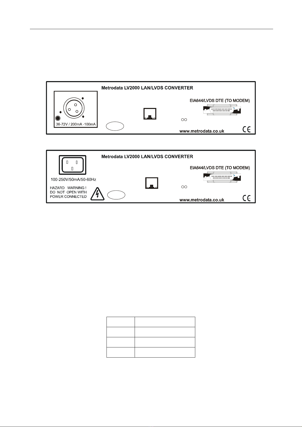
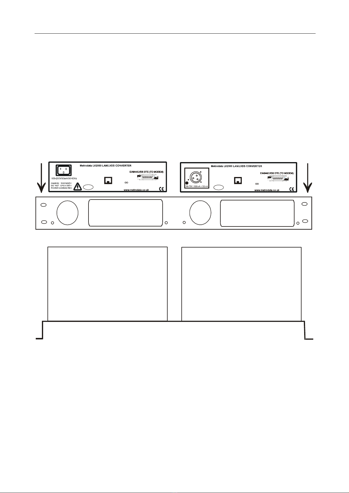
2. 1 Rear panel
All connections into and out of the LV2000 are made through the rear panel which is shown
in schematic form for both AC and DC models below.
Figure 2. 1 LV2000 AC and DC rear panels
2. 2 Power Supply
The LV2000 is powered by a mains supply with an input voltage of 100-250VAC 50-60Hz
and with an input current of 50 mA. The LV2000 is provided ex-factory with a 1A internal
fuse. Mains power is connected via the IEC socket on the rear of the unit.
An alternative -48VDC powered unit is available. The input voltage and current ranges are -
minus 36 to minus 72 volts DC, 200 - 100mA. A Buccaneer type socket is fitted to the rear
panel, and a plug is provided with the unit for the customer’s own wiring. The connections
are labelled on the rear panel of the LV2000.
On some units, an additional Ground stud may be located on the rear panel to permit a
separate Ground connection to be made.
Figure 2. 2 -48VDC connections
Note: The LV2000 must be connected to safety earth for correct operation.
Pin no Connection
1-48VDC
2 Ground
30VDC
SUBSCRIBER PORT
10/100 BASE T
LINK/ACT SPEED
Made in
UK
Tx Rx
DTE Activity
(CRYPTO RED)
SUBSCRIBER PORT
10/100 BASE T
LINK/ACT SPEED
Pin1
-48V
Pin3
0V
L
_
_
Made in
UK
Tx Rx
DTE Activity
(CRYPTO RED)

LV2000 DESCRIPTION OF PARTS
5
2. 3 LVDS EIA-644 DTE Port
The LVDS interface is presented on a 25-way male D-type connector. The rear panel
connector layout is shown below:
Figure 2. 3 LV2000 DTE port D-type connector layout
*optionally driven LVDS or LVTTL outputs
Pin Direction Signal name
1
2 SD(A) Send Data(A)
3 RD(A) Receive Data(A)
4 RS(A)*Request to Send (A)
5
6
7 Ground Signal Ground
8 RR(A) Receiver Ready(A)
9 RT(B) Receive Timing(B)
10 RR(B) Receiver Ready(B)
11 TT(B) Terminal Timing(B)
12 ST(B) Send Timing(B)
13
14 SD(B) Send Data(B)
15 ST(A) Send Timing(A)
16 RD(B) Receive Data(B)
17 RT(A) Receive Timing(A)
18
19 RS(B)*Request to Send (B)
20
21
22
23
24 TT(A) Terminal Timing(A)
25
LV2000 DESCRIPTION OF PARTS
6
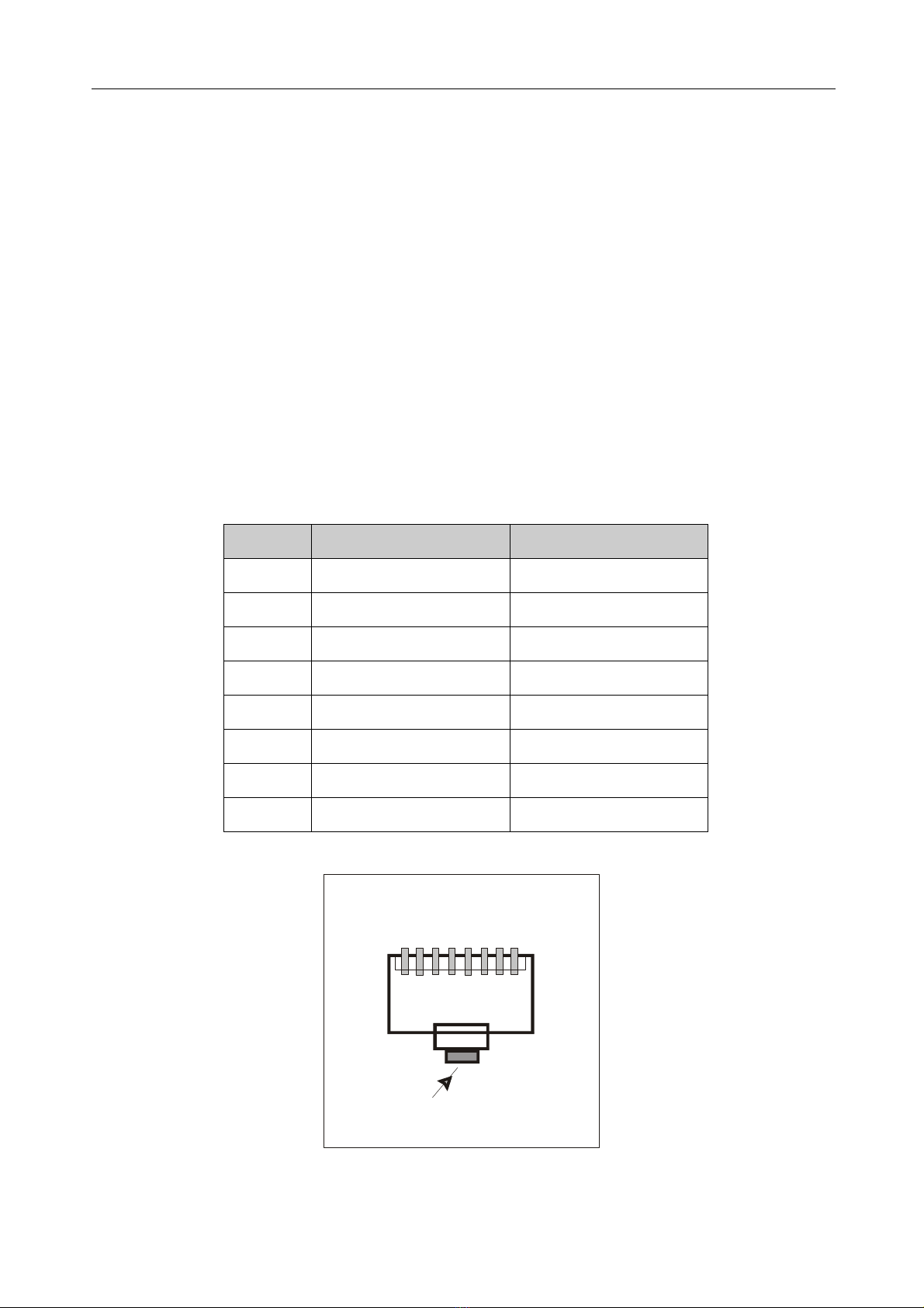
2. 4 LAN port
The LAN port is presented on an RJ45 female connector mounted on the rear panel of the
LV2000. The port automatically senses the LAN interface and switches between MDI and
MDI-X configurations. This removes the potential requirement for Crossover cables when
connecting LANs to the LV2000 whatever LAN equipment is being used. The port also
automatically negotiates the LAN speed and operates at either 10 Mbps or 100 Mbps, and
negotiates whether operation should be in full or half duplex mode, providing that it is
negotiating with another auto-negotiating port. If it negotiates with a fixed port, it can identify
the speed, but it cannot distinguish the full/half duplex mode status, and consequently
selects half duplex operation. Such operation is prone to errors and should be avoided by
setting AUTONEGOTIATION to DISABLED and manually selecting the correct SPEED and
DUPLEX mode of operation using bit-switches 6, 7 and 8. See section 3 of this guide.
There is a miniature LED on the lower right corner of each RJ45 socket on the rear panel
which is illuminated yellow when operation is at 100 Mbps. The miniature LED on the lower
left corner of each RJ45 socket is illuminated green when the link is up, and flashes when
there is activity on the link. The RJ45 connector layout for an auto-sensing MDI/MDI-X port
is shown below:
:
Figure 2. 4 LAN port connector layout
Figure 2. 5 RJ45 connector layout
Pin No MDI Signal MDI-X Signal
1Tx Data +ve Rx Data +ve
2Tx Data -ve Rx Data -ve
3Rx Data +ve Tx Data +ve
4Not used Not used
5Not used Not used
6Rx Data -ve Tx Data -ve
7Not used Not used
8Not used Not used
8 7 6 5 4 3 2 1
LOCKING TAB
INSTALLATION & SET-UP
7
3 INSTALLATION & SET-UP
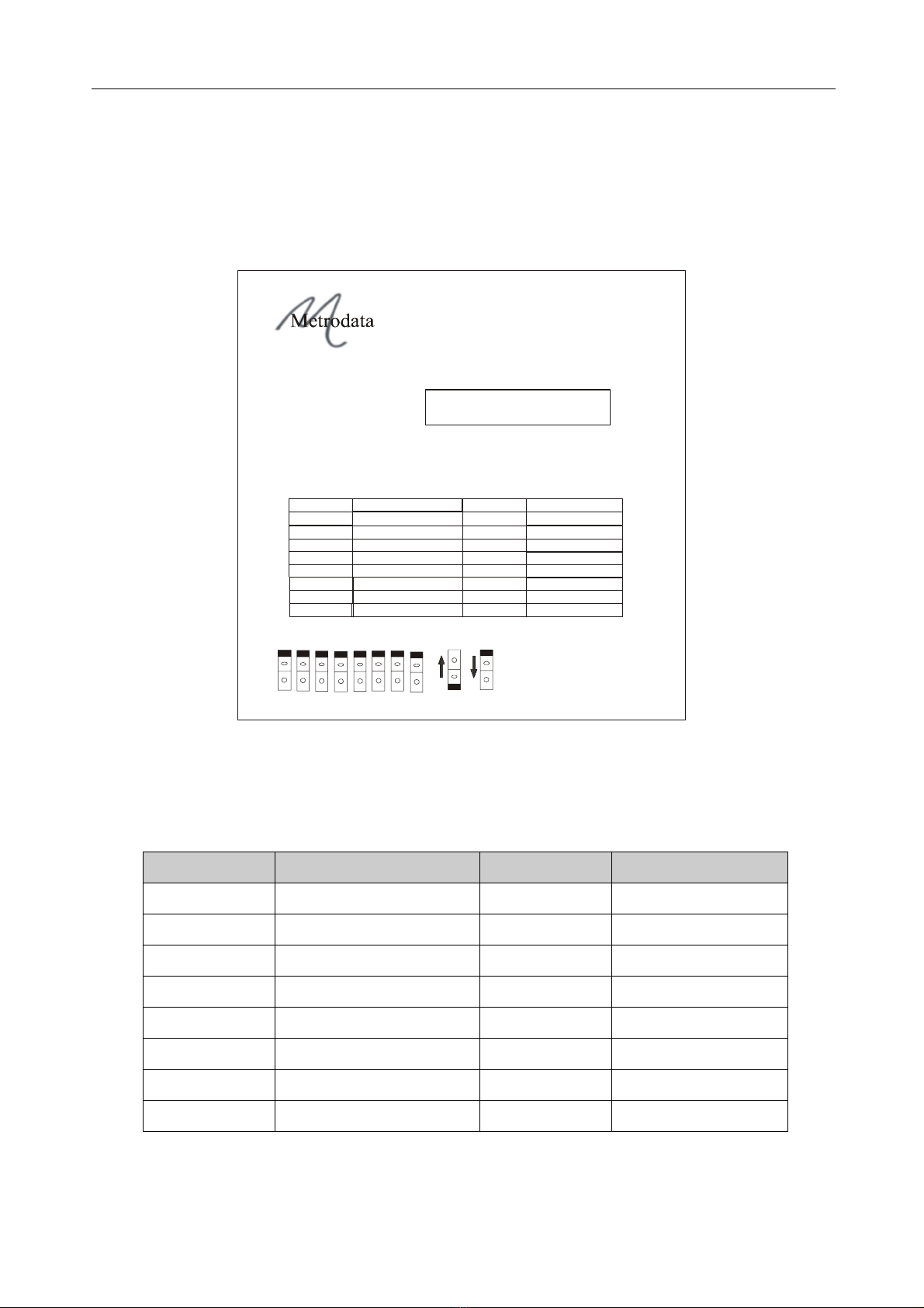
3. 1 Setting-up the Bit-switches
The Bit-switches on the base of the unit must be set-up before making any connections to
the unit. There is an explanatory label on the unit’s base which defines the bit-switch set-up
options.
Figure 3. 1 LV2000 Base Panel label
3 . 1. 1 Bit-switch definitions
The default settings of the bit-switch are shown in bold:
Figure 3. 2 Bit-switch definitions
Bit-switch Control On Off
1Unused Normal
2Crypto Resynch Disabled Enabled
3Resynch Mode Active Low Active High
4Resynch Control LVDS LVTTL
5Data Invert Normal Inverted
6Duplex Half Full
7Speed 10M 100M
8Auto Negotiation Enabled Disabled
LVDS LAN CONVERTER (AC)
LV2000
For product manual
and other information:-
Metrodata Ltd
TW20 8RY UK
Tel +44 (0) 1784 744700
Fax +44 (0) 1784 744730
17-08-637A
Part No.80-05-558
OFF
ON
www.metrodata.co.uk
Manufactured in the UK
Serial No:
48708
12
345678
This device complies with part 15 of the FCC rules
Operation is subject to the following two conditions:
(1) This device may not cause harmful Interference, and
(2) This device must accept any interference received,
including interference that may cause undesired operation.
Bold character
s = Factory Default
Bitswitch Control ON OFF
1
2
3
5
Resync Control
Normal
Half
Data Invert
Duplex
7
8
Speed 10M
Enabled
Disabled
100M
LVTTL
Inverted
Full
4
6
Normal
Disabled
A
ctive Low
LVDS
Auto Negotiation
Resync Mode
Active High
Crypto Resync
Enabled
Unused
LED Status:
GREEN ON - Unit OK
GREEN FLASH - Link Down
RED FLASH - LVDS Link Down
RED ON - Both Links Down

INSTALLATION & SET-UP
8
3 . 1. 2 Crypto Resynch
Bit-switch ON: The Crypto Resynch function is DISABLED
Bit-switch OFF: The Crypto Resynch function is ENABLED. when the LV2000 detects a loss
of synch on the receive data, it will pulse the RS control signal for half a second and then
wait for 5 seconds before checking for synchronisation again.
3 . 1. 3 Resynch Mode
Bit-switch ON: Normal Sate of Resynch control is High (Bit-switch in ON position). Resynch
pulse will be Low (OFF) when ENABLED.
Bit-switch OFF: Normal Sate of Resynch control is Low (Bit-switch in OFF post ion). Resynch
pulse will be High (ON) when ENABLED.
Note: The above High/Low states refer to the A signal of a differential pair.
3 . 1. 4 Resynch Control
Bit-switch ON: The Resynch control will be differential LVDS.
Bit-switch OFF: The Resynch control will be single ended LVTTL
3 . 1. 5 Data Invert
Bit-switch ON: Normal operation.
Bit-switch OFF: The data is inverted.
3 . 1. 6 Duplex
Bit-switch ON: LAN port operates Half Duplex in manual mode, ignored in Auto-Negotiate
mode.
Bit-switch OFF: LAN port operates Full Duplex in manual mode, ignored in Auto-Negotiate
mode.
3 . 1. 7 Speed
Bit-switch ON: LAN port operates at 10Mbps in manual mode, ignored in Auto-Negotiate
mode.
Bit-switch OFF: LAN port operates 100Mbps in manual mode, ignored in Auto-Negotiate
mode.
3 . 1. 8 Auto Negotiation
Bit-switch ON: LAN port Auto Negotiates for Speed and Duplex.
Bit-switch OFF: LAN port uses manual settings for Speed and Duplex.
Note: The IEEE802.3 Auto-Negotiation standard allows for operation with ports that support
either Auto-Negotiation or a fixed configuration. Note that when operating with a fixed
configuration port, the Auto negotiation function can ONLY detect the speed of the link. The
fixed link will always be assumed to be half duplex.

INSTALLATION & SET-UP
9
3. 2 LV2000 Crypto Resynch Operation
When operating with a serial encryption unit, it is possible that the decryption function will
lose synchronisation, with the result that the data being received by the LV2000 unit is
invalid. When synchronisation is lost, it is useful for the LV2000 to be able to detect this and
automatically take action to resynchronise and restore the data link.
The LV2000 uses HDLC encapsulation for the serial data link and uses this protocol to detect
synchronisation loss. HDLC uses a checksum to validate all frames and the LV2000 will
declare loss of synch if 10 consecutive frames are received containing errors.
Providing that Crypto resynch function is ENABLED, when the LV2000 finds that it has lost
synch it will pulse the RS output signal for half a second before then restoring it to its normal
state. It will then wait for 5 seconds to allow the crypto to perform its initialisation and
synchronisation functions before checking for synch again. If the link is still out of synch, the
process will repeat with another RS pulse.
To ensure maximum flexibility, the state of the RS pulse can be set to either High or Low to
initiate Resynch action. When Crypto resynch is DIASABLED, the RS output will assume the
normal High (ON) state.
In addition, in order to support the widest range of Crypto equipment, the RS signal may be
set to be driven as either Differential LVDS, or as a single ended LVTTL signal.
3. 3 Connecting up
Safety Notice: Ports that are identified as SELV in this manual should only be connected to
SELV ports on other equipment in accordance with EN 60950 clause 2.3.
Step 1: Mounting.
The LV2000 is housed in a convenient 1U table top enclosure. 19 inch rack nests for two
or 18 units are available as options.
Step 2: Set up Bit-switches
These switches are located on the base of the unit and are used to configure the unit.
Step 3: Power Supply
Finally, connect the main power lead and re-check all connections for security. Then turn on
the power supply.
Warning: Do not connect the LV2000 to excessive voltage. Read the safety information
before continuing.
Step 4: LAN ports
Connect the LV2000 to the RJ45 LAN port on the rear panel. The indicator lights on the lower
corners of the RJ45 socket indicate the LAN speed and activity status.
Step 5: LVDS port
Connect the satellite modem to the EIA-644 LVDS port using an appropriate cable type for
the satellite modem interface. The DTE activity LED on the rear panel will indicate the link
status.
INSTALLATION & SET-UP
10
3. 4 Optional rackmounting
Rackmounting kits may be used to mount two LV2000 units side by side in a 19” rack.
The kit, Part no 80-05-256, has a recessed plate to permit cable or fibre bends to be made
within the envelope of a 19” rack. It also has a single cut-out for all connections to the rear
of the LV2000. The installation method is the same in all cases.
First remove the two rear panel screws securing each unit’s lid. Fasten the two LV2000 units
to the rackmount adaptor plate using the screws that you have removed, as shown in the
illustrations below.
Then secure the rack mounting plate complete with the two LV2000 units to the 19” rack
using the locating holes at the ends of the adaptor plate. If you have set the bit-switches on
the base plate of the units before fixing them to the adaptor plate, check that the settings are
still correct.
Figure 3. 3 2-unit recessed rackmounting plan & elevation
Recessed space to accommodate cable bends
LV2000 LV2000
SUBSCRIBER PORT
10/100 BASE T
LINK/ACT SPEED
Made in
UK
Tx Rx
DTE Activity
(C RY PTO RE D)
SUBSCRIBER PORT
10/100 BASE T
LINK/ACT SPEED
Pin1
-48V
Pin3
0V
L
_
_
Made in
UK
Tx Rx
DTE Activity
(CRYPTO RED)

LV2000 TROUBLESHOOTING & TESTING
11
4 LV2000 TROUBLESHOOTING & TESTING
4. 1 Establish and verify the LAN link
Connect the LAN cable to the LAN port. If the LED on the bottom left hand corner of the RJ45
socket goes green, or flashes green, then there is a LAN connection. If the LED remains
unlit, there is no LAN connection, and investigatory action should be taken on the LAN and/
or its cables.
Note that for 100M Full Duplex operation between the LV2000 and a fixed (i.e. non-
negotiating) LAN port, bit-switch 6 must be set to FULL (OFF state) and Bit-switch 7 must
be set to 100M (OFF state). Bit-switch 8 must also be set to DISABLED (OFF state) in order
to prevent Auto-negotiation.

LV2000 SPECIFICATIONS
12
5 LV2000 SPECIFICATIONS
Disclaimer
Metrodata Ltd makes no representations or warranties with respect to the contents hereof and specifically dis-
claims any implied warranties or merchantability or fitness for any particular purpose. Further, Metrodata Ltd
reserves the right to revise this publication and to make changes from time to time in the content hereof without
obligation of Metrodata Ltd to notify any person of such revision or changes.
Trademarks
The Trademarks of other Corporations which may be used in this manual are hereby acknowledged.
Copyright © 2007 by Metrodata Ltd
All Rights Reserved
DTE Interfaces Definition
DTE Interfaces EIA-644 LVDS port
Framing Unframed
Encapsulation HDLC
Clocking options LVDS port: DCE supplied clock
Line Rate LVDS: 52Mbps
Max packet rate 93913 64 byte packets per second, full duplex at 52 Mbps
LED Indicators DTE Tx and Rx Activity, LAN Speed & Activity
Alarms & Loopbacks None
LAN Port Definition
LAN Interface RJ45, Auto switched MDI or MDI-X, or fixed MDI selected by bit-switch
Operating mode Auto negotiated 10/100 Mbps Full / Half Duplex, or Manually selected by
bit-switches.
Port filtering rate 148810 packets per second, 64 byte packets
MAC address table 4096 entries
Min/Max Packet size 64 bytes / 1536 bytes (larger packets are discarded)
General Definition
Power supply 100-250 VAC, 50-60 Hz, 25 mA or
-36 to -72 VDC, 100-200mA
Dimensions 202 x 132 x 44 mm (w x d x h) Enclosure only
202 x 132 x 47 mm (w x d x h) Overall including feet
Environmental Range
Ambient Temperature 0 degC to +50 degC
Storage Temperature -20 degC to +70 degC
Relative Humidity 0% - 95% non condensing
Barometric Pressure 86 KPa - 106 KPa
This manual suits for next models
1
Table of contents
Other Metrodata Media Converter manuals


Popular Media Converter manuals by other brands

KVMSwitchTech
KVMSwitchTech HDMI-CATSPB-8 instruction manual

AUDIOBYTE
AUDIOBYTE Hydra Z owner's manual

Sollae Systems
Sollae Systems CSW-H85N user manual

Samson
Samson 6000 Series Mounting and operating instructions

Converters.TV
Converters.TV 998 Scan converter Operation manual

MyTek
MyTek 8X192 ADDA user manual


