Metrodata DC3 00 Series User manual
DC3X00
www.metrodata.co.uk
Metrodata DC3X00 User Manual
Metrodata Ltd
Laxton House
Crabtree Office Village
Eversley Way
Egham
Surrey TW20 8RY
United Kingdom
tel: +44 (0) 1784 744700
fax:+44 (0) 1784 744701
website: www.metrodata.co.uk

1 INTRODUCTION 1
1. 1 About the DC3X00 1
1. 2 Safety 2
1. 3 Electromagnetic Compatibility 2
1. 4 EN50022 Declaration 2
1. 5 FCC Declaration 2
1. 6 Power supply 2
1. 7 FCC Declaration 2
1. 8 Technical Overview 3
1 . 8. 1 G.703 Signal Transmission 3
1 . 8. 2 G.704 Framing 3
1 . 8. 3 E1 Path Overhead 4
1. 9 DTE Nx64K Payload 4
2 DESCRIPTION OF PARTS 5
2. 1 Rear panel 5
2. 2 Status display - rear panel 5
2. 3 Power supply 6
2. 4 Unbalanced E1 Line port (BNC) 7
2. 5 Balanced RJ45 E1 Line (Network) Port 8
2 . 5. 1 Connecting to a terminal device 8
2 . 5. 2 Connecting to a network device 9
2 . 5. 3 RJ45 Connector layout 9
2 . 5. 4 Cable lengths and types 10
2. 6 Alarm Extension (RJ45) 10
2. 7 X.21 DTE Port 11
2. 8 V.35 DTE Port 12
3 INSTALLATION & SET-UP 13
3. 1 Setting-up the Bit-switches 13
3 . 1. 1 Select RJ45/BNC 14
3 . 1. 2 CRC4 and T/S 16 bypass 14
3 . 1. 3 Framing 14
3 . 1. 4 Timeslot 16 by-pass & bandwidth 14
3 . 1. 5 Setting Up Start T/S and Bandwidth 15
3 . 1. 6 Timing 15
3 . 1. 7 Line coding 16
3 . 1. 8 Test Loop 16
3. 2 Connecting up 17
4 ALARMS, TROUBLESHOOTING & TESTING 18
4. 1 Alarms 18
4. 2 Troubleshooting 19
4. 3 Test Loop 20
5 DC3X00 SPECIFICATIONS 21
5. 1 DC3X00 Product Specification 21
5. 2 DC3X00 Clocking Diagram 22
5. 3 Glossary 23

INTRODUCTION
1
1 INTRODUCTION
1. 1 About the DC3X00
The DC3X00 is used to interface between a fractional E1 (2.048Mbit/s) Nx64K service and
an X.21 or V.35 port which connects to a bridge or router. The model DC3000 has an X.21
interface, and the model DC3200 has a V.35 interface. Both models are described in this
manual. There is a choice of either BNC or RJ45 connectors for the E1 service on the rear
panel of the unit. DC3X00’s are used in pairs, one on either side of a WAN (Wide Area
Network) link.
LAN
LAN
Figure 1.1 DC3X00 installation

INTRODUCTION
2
1. 2 Safety
The DC3X00 should not be connected to cabling which would be required by BS6701 to be
equipped with over-voltage protection. The following ports are designated SELV (Safety
Extra Low Voltage) within the scope of EN41003:
X.21 port
V.35 port
Fractional E1 Line port (BNC or RJ45)
Alarm extension RJ45 port
These ports should only be connected to SELV ports on other equipment in accordance with
EN60950 clause 2.3.
1. 3 Electromagnetic Compatibility
In order to ensure EMC compliance all signal and data cables and connectors must use a
screened connector shell with a screened cable. The cable screen must be terminated to the
screened connector shell and not connected to any pins of the connector. Failure to use the
correct connector may compromise EMC compliance.
1. 4 EN50022 Declaration
The DC3X00 is a Class A product. In a domestic environment it may cause radio interference
in which case the user may be required to take adequate measures.
1. 5 FCC Declaration
This equipment has been tested and found to comply with the limits for a Class A digital
device, pursuant to Part 15 of the FCC Rules. These limits are designed to provide
reasonable protection against harmful interference when the equipment is operated in a
commercial environment. This equipment generates, uses, and can radiate radio frequency
energy and, if not installed and used in accordance with the instruction manual, may cause
harmful interference to radiocommunications. Operation of this equipment in a residential
area is likely to cause harmful interference in which case the user will be required to correct
the interference at its own expense.
1. 6 Power supply
The DC3X00 is powered by a mains power supply with an input voltage range 100-250 VAC/
50-60 Hz.
An alternative -48V DC power supply unit is available.
Further details are given in Section3.
Safety notes:
Excessive voltages are present inside the unit. There are no user serviceable parts inside
the unit, and the cover should not be removed by unqualified personnel. The unit must not
be exposed to damp or condensing conditions. The DC3X00 must be connected to safety
earth for correct operation.
1. 7 FCC Declaration
This equipment has been tested and found to comply with the limits for a Class A digital
device, pursuant to Part 15 of the FCC Rules. These limits are designed to provide

INTRODUCTION
3
reasonable protection against harmful interference when the equipment is operated in a
commercial environment. This equipment generates, uses, and can radiate radio frequency
energy and, if not installed and used in accordance with the instruction manual, may cause
harmful interference to radiocommunications. Operation of this equipment in a residential
area is likely to cause harmful interference in which case the user will be required to correct
the interference at its own expense.
1. 8 Technical Overview
The DC3X00 is used on unframed E1/G.703, framed E1/G.704 (CRC4) or
E1/G.704 (no CRC4)digital services. Technical overviews of G.703 and G.704 are provided.
1 . 8. 1 G.703 Signal Transmission
The signal is transmitted on 75 ohm unbalanced coax or 120 ohm balanced twisted pair. The
signal has alternate mark inversion (AMI) characteristics in accordance with G.703. A mark
is transmitted as a 0.5 unit interval (UI) wide pulse of amplitude 2.37V on 75 ohm coax, or
3.0V on 120 ohm twisted pair. Alternate marks have opposing polarity so that '111' is
transmitted as a positive pulse, a negative one and then another positive one. The pulses
have a duration of 50% so that strings of '1s' can be identified as a series of pulses. This is
because clocking information is derived from the transmitted signal. In addition, strings of
zeros are replaced with high-density binary 3 (HDB3) code words to ensure pulse density
(and therefore clocking information) and an average DC potential of 0V.
The transmission rate is 2.048 Mbps. The worst case delay through the DC3X00 is 2
milliseconds, and the worst case round trip delay is 8 milliseconds.
1 . 8. 2 G.704 Framing
Groups of 248 bits are grouped into frames together with an 8-bit overhead at the start of the
frame called TIME SLOT 0 (TS0). The frame length is therefore 256 bits, and the frame
repetition rate is 8KHz. The 248 bits of payload are divided into 31 timeslots of 8 bits each
(TS1 - TS31). With the data in each timeslot regarded as an individual channel, 31 channels
may be multiplexed together into one E1 trunk. As well as dividing the trunk between payload
and overhead, groups of frames are associated into multi-frames. A synchronisation pattern
is spread across the multiframe. Frames are alternately FAS (Frame Alignment Signal) and
NFAS (Non Frame Alignment Signal) frames.

INTRODUCTION
4
1 . 8. 3 E1 Path Overhead
8 bits are used for path overhead and provide framing, alarm information, error detection and
management. The bits of TS0 are used alternatively by the FAS and NFAS frames as
follows:
Figure 1.2 E1 Path overhead
1. 9 DTE Nx64K Payload
The DC3X00 permits the 2.048Mbits/s E1 LINE port to operate with multiple channels of
Nx64Kbit/s where N may vary between 1 and 31. There are restrictions placed upon the
utilisation of bandwidth:
Timeslots used must form a contiguous block
The total number of timeslots allocated must be less than or equal to 31 (or 30 if Timeslot 16
is by-passed).
If Timeslot 16 by-pass is ENABLED by setting the bit-switch labelled BYP16 to ON,
Timeslot 16 is by-passed in allocating channels sequentially to timeslots; i.e. you could then
select Timeslots ….14,15,17,18…….
Bit No Function
FAS Frame
1CRC bit
2 to 8 Frame alignment signal (FAS) 0011011
NFAS Frame
1International bit : contains CRC multi-
frame alignment signal and remote block
error (REBE) information
2NFAS bit
3Remote alarm indication (RAI)
4 to 8 National bits
DESCRIPTION OF PARTS
5
2 DESCRIPTION OF PARTS
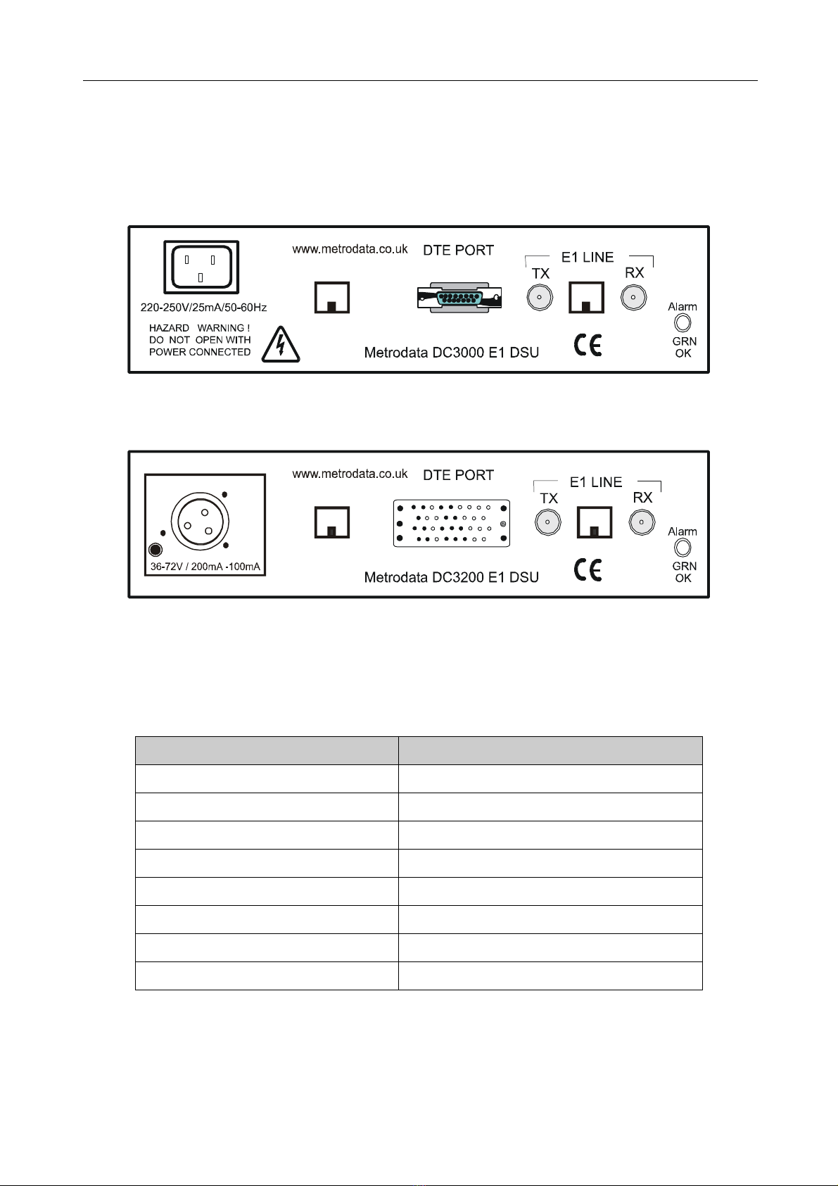
2. 1 Rear panel
All connections into and out of the DC3X00 are made through the rear panel. The rear panels
are shown in schematic form below.
ALARM
EXT
ALARM
EXT
Pin1
-48V
Pin3
0V
L
_
_
Figure 2.1 DC3000 rear panel (100-250 VAC supply)
Figure 2.2 DC3200 rear panel (-48VDC supply)
2. 2 Status display - rear panel
There is a status LED on the right hand side of the rear panel which indicates the status of
the unit as shown in the figure below.
Figure 2.3 Rear panel status LED
Status LED Meaning
Off No mains power present
Red steady LOS
Red/Off flashing LOS and DTE Alarm
Red/Green flashing LOF or AIS Alarm
Red/Green/Off flashing AIS and DTE Alarm
Green/Red/Off flashing LOF and DTE Alarm
Green/Off flashing DTE Alarm
Green steady DC3X00 is operating normally

DESCRIPTION OF PARTS
6
Notes:
If the LED flashes red/green, disconnect the DTE (X.21 or V.35) signal to the DC3X00 in
order to distinguish between LOF and AIS alarms. The loss of the DTE signal will then cause
either the red/green/off or the green/red/off sequence to occur, depending upon the
condition which has occurred.
2. 3 Power supply
The DSU is powered by a mains supply with an input voltage of 100-250VAC, 50-60Hz,
35-15 mA. The input power consumption is approximately 3.5 watts. The DC3X00 is
provided ex-factory with a 250mA internal fuse. Mains power is connected via the IEC inlet
on the rear of the unit.
An alternative -48VDC powered unit is available. The input voltage and current ranges are
minus 36 to minus 72 volts DC, 100-50mA. A Buccaneer type socket is fitted to the rear
panel, and a plug is provided with the unit for the customer’s own wiring. The connections
are labelled on the rear panel of the DC3X00.
On some units, an additional Ground stud may be located on the rear panel to permit a
separate Ground connection to be made.
Figure 2.4 -48VDC connections
Note: The DSU must be connected to mains safety earth for correct operation.
Pin no Connection
1-48VDC
2 Ground
30VDC

DESCRIPTION OF PARTS
7
2. 4 Unbalanced E1 Line port (BNC)
The network is connected to the BNC connectors at the rear of the unit as shown below :
Figure 2.5 BNC connection
Cable lengths should be restricted to those defined below:
Figure 2.6 Cable lengths
Note: The total maximum attenuation of each of the cables attached to the network port must
not exceed 6dB when measured at 1024 MHz. The frequency/attenuation characteristic of
the cables attached to the network port shall follow a root frequency law.
Pin Function
Tip Signal
Ring Shield
Cable Max Length (metres)
UR202 720
RG59U 600
BT2002 650
BT2003 680

DESCRIPTION OF PARTS
8
2. 5 Balanced RJ45 E1 Line (Network) Port
The layout of the female RJ45 network port mounted on the rear panel is shown below:
Figure 2.7 RJ45 network port layout
2 . 5. 1 Connecting to a terminal device
A connecting cable from the network port to a terminal port such as a router or a PABX is
straight through. Connections are defined in the table below.
Figure 2.8 Connection from DSU to terminal device
Pin Function
1Tx tip
2Tx ring
3Tx shield
4Rx tip
5Rx ring
6Rx shield
7Not connected
8 Not connected
DSU
port pin
DSU port
function
Terminal port
pin
Terminal port
function
1Tx tip 1Rx tip
2Tx ring 2Rx ring
3Tx shield 3Rx shield
4Rx tip 4Tx tip
5Rx ring 5Tx ring
6Rx shield 6Tx shield
7Not connected Not connected Not connected
8 Not connected Not connected Not connected

DESCRIPTION OF PARTS
9
2 . 5. 2 Connecting to a network device
A connection from the network port to a network device such as an E1 line or an NTU
requires a crossover cable. Connections are defined in the table below.
Figure 2.9 Connection from DSU to network device
2 . 5. 3 RJ45 Connector layout
Figure 2.4 shows both the plug and socket head on so that any connecting wires are behind
the connector. The connector numbering is shown.
1234567
8
8 7 6 5 4 3 2 1
LOCKING TAB
Figure 2.10 RJ45 layout
DSU
port pin
DSU port
function
Network port
pin
Network port
function
1Tx tip 4Rx tip
2Tx ring 5Rx ring
3Tx shield 6Rx shield
4Rx tip 1Tx tip
5Rx ring 2Tx ring
6Rx shield 3Tx shield
7Not connected Not connected Not connected
8 Not connected Not connected Not connected

DESCRIPTION OF PARTS
10
2 . 5. 4 Cable lengths and types
Cable lengths should be restricted to those defined below:
Figure 2.11 Cable lengths
Note: The total maximum attenuation of the cable attached to the network port must not
exceed 6dB when measured at 1024 MHz. The frequency/attenuation characteristic of the
cables attached to the network port shall follow a root frequency law. This port type is
approved to CTR12, CTR13.
2. 6 Alarm Extension (RJ45)
The alarm extension is an RJ45 female socket mounted on the rear panel of the unit. It allows
the connection of major and minor alarm relay contacts to a remote indicator such as a bell
or a lamp. The alarm relay port is regarded as a SELV port within the scope of EN41003.
Mains power failure is registered via Normally closed contacts as a major alarm.
Figure 2.12 RJ45 alarm extension layout
Cable Max Length
(metres)
Belden 8132 (28 AWG) 175
Belden 9841 (24 AWG) 300
Pin Function
1Major Normally Closed
2Major Normally Open
3Major common
4Not connected
5Minor Normally Open
6Minor Normally Closed
7Minor common
8Ground

DESCRIPTION OF PARTS
11
2. 7 X.21 DTE Port
The X.21 DTE port is equipped with a 15-way female D-type connector in accordance with
ISO 4903. The connections are shown below.
Note: The X.21 port is regarded as a SELV port within the scope of EN 41003.
Figure 2.13 X.21 DTE port connector layout
Pin No Function Definition CCT No.
1Chassis Shield 101
2Tx(A) Transmit (A) 103
3C(A) Control (A) 107
4Rx(A) Receive (A) 104
5I(A) Indication (A) 109
6S(A) Signal timing (A) 115
7X(A) DTE Signal timing (A) 113
8Ground Ground 102
9Tx(B) Transmit (B) 103
10 C(B) Control (B) 107
11 Rx(B) Receive (B) 104
12 I(B) Indication (B) 109
13 S(B) Signal timing (B) 115
14 X(B) DTE Signal timing (B) 113
15 Not connected

DESCRIPTION OF PARTS
12
2. 8 V.35 DTE Port
The V.35 DTE port is equipped with a 34-way M rack female connector in accordance with
ISO 4903. The connections are shown below.
Note: The V.35 port is a SELV port within the scope of EN 41003.
Figure 2.14 V.35 DTE port connector layout
Pin Function Definition CCT No.
AChassis Chassis ground 101
BGround Signal ground 102
CRTS Request to send 105
DCTS Clear to send 106
EDSR Data set ready 107
FDCD Data Carrier detect 109
HDTR Data terminal ready 108.2
PTx(A) Transmit data(A) 103
RRx(A) Receive data(A) 104
STx(B) Transmit data(B) 103
TRx(B) Receive data(B) 104
UXClk(A) Terminal timing(A) 113
VRxClk(A) Receive timing(A) 115
WXClk(B) Terminal timing(B) 113
XRxClk(B) Receive timing(B) 115
YTxClk(A) Transmit timing(A) 114
AA TxClk(B) Transmit timing(B) 114
INSTALLATION & SET-UP
13
3 INSTALLATION & SET-UP
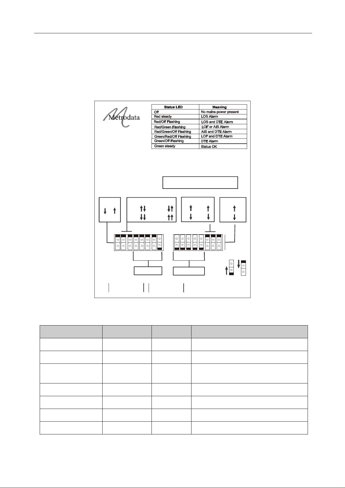
3. 1 Setting-up the Bit-switches
It is recommended that the two sets of 8-gang bit-switches labelled SW1 and SW2 on the
base of the unit are set-up before making any connections to the unit. There is an
explanatory label on the unit’s base which defines the bit-switch set-up options and alarms.
Serial No:
DC3X00 BNC/RJ45 E1 DSU
Build Rev: 72-01-380-3 X.21
Build Rev: 72-01-380-4 V.35
1
0
For product manual
and other information:-
www.metrodata.co.uk
Metrodata Ltd
TW20 8RY UK
Tel +44 (0) 1784 744700
Fax +44 (0) 1784 744730
SW1 SW216 8 4 2 1
START T/S
16
84 21
BANDWIDTH
SW1
SW2
17-08-115C
CLOCK SELECT
INT TERM
LOOP
BYP16 CRC4
ON
OFF
SELECT
RJ45
BNC
TEST
LOOP
OFF ON
DTE
MODE
Figure 3.1 DC3X00 Base Panel label
Figure 3.2 Bit-switch definitions
Parameter Label Unit Options
E1 Line connector Select Up Down RJ45 BNC
Framing CRC4 On Off CRC4 No CRC4
By-pass T/S16 BYP16 On
Off
By-Pass T/S16
T/S 16 Carries Payload
Bandwidth Bandwidth Binary Switch 2 Binary Switches 0-31
Start timeslot Start T/S Binary Switch 1 Binary Switches 0-31
Timing Clock select Position Internal, Terminal, Loop, DTE Mode
Test Test Loop On Off Run Test Loop No test

INSTALLATION & SET-UP
14
3 . 1. 1 Select RJ45/BNC
This single switch is used to select which type of connector is to be used to connect the E1
line.
3 . 1. 2 CRC4 and T/S 16 bypass
These two switches define whether CRC4 checking is to be done on the E1 line, and whether
T/Slot 16 is to be bypassed.
Figure 3.3 CRC4 & Timeslot options
3 . 1. 3 Framing
UNFRAMED mode can be selected by setting the BANDWIDTH bit-switches to 0 (zero).
When this is done, the START T/S switches have no effect, and the unit remains in
UNFRAMED mode.
In G.704(no CRC4) mode, TS0 is used to provide framing information. Bit 1 in TS0 is set to
1 and no data error checking occurs.
In G.704(CRC4) mode, TS0 is used to provide framing information and a Cyclic Redundancy
Check (CRC) is performed to test for data errors. Note that FALLBACK can occur from
G.704(CRC4) mode.
Fallback is a mechanism used in a CRC4 environment which allows G.704 framing to be
maintained in the presence of high levels of CRC errors. In effect the receiver falls back to
G.704 (no CRC4) mode. This allows traffic to pass from a CRC4 framed device to a non-
CRC4 device without generating a Loss of Frame alarm (LOF).
3 . 1. 4 Timeslot 16 by-pass & bandwidth
With Timeslot 16 by-pass OFF, TS16 may be used for payload. With by-pass ON, TS16 is
always left idle. Thus, if by-pass is ON and START TIMESLOT is set to 15 and Nis set to 2,
then TS15 and TS17 are used and TS16 is by-passed.
CRC4 Comment
On (Enabled) TS0 for framing info & CRC4 data integrity check on frame
Off (Disabled) TS0 for framing info, no data integrity check on frame
By-pass
T/S16
No of payload
T/Slots
Bandwidth
nx64K
Comment
On 30 max (n =1-30) x 64K TS16 by-passed for payload
Off 31 max (n =1-31) x 64K TS16 can carry payload

INSTALLATION & SET-UP
15
3 . 1. 5 Setting Up Start T/S and Bandwidth
The 5 binary switches for START TIMESLOT and BANDWIDTH permit numbers from 0-31
to be set-up. The decimal values of each switch are shown on the label.
Thus, a START T/S of 11 and a BANDWIDTH of 4 would be set up as below.
Figure 3.4 Binary set-up
Permitted BANDWIDTH values are 1-30 with Bypass ON and 1-31 with Bypass OFF.
3 . 1. 6 Timing
TIMING is set by two bit-switches and determines the source for the LINE E1 transmit clock,
the V.35/X.21 Transmit timing and the V.35/X.21 Receive timing.
The options are as follows:
INT (internal oscillator)
LOOP (E1 loop timing)
TERM (Terminal, i.e V.35/X.21 transmit is supplied by terminal device), or
DTE MODE (where the terminal device supplies timing for both directions of
transmission)
Note that when using TERM or DTE MODE, the terminal supplied clock must be accurate to
within 50 ppm of the Nx64K value. If the DTE clock is out of specification the E1 transmitter
will free-run at 2048 MHz.
The recommended timing mode for the DC3X00 pair at either side of an E1 circuit (which is
not supplying timing), is Internal at one end of the link and Loop at the other end.
However, there are many other potentially valid timing mode combinations for a pair of
DC3X00 units, and it is important to ensure that the terminal equipment timing modes also
form part of the overall network design.
Start T/S Bandwidth
01011 00100

INSTALLATION & SET-UP
16
The tables below provide detailed timing definitions
Figure 3.5 DC3200 timing signal definitions
Figure 3.6 DC3000 timing signal definitions
3 . 1. 7 Line coding
Line coding is HDB3 (High-Density Binary 3). This setting is built into the unit and cannot be
altered. Therefore there is no bit-switch for ths item.
3 . 1. 8 Test Loop
This switch is used to initiate loop testing. Further detail is available in the next section.
Care should be taken when using loops, especially with TERM (Terminal) timing mode, as
invalid network clocking scenarios can be created.
Clocking mode Bit switch
position
E1 Transmit clock
source
V.35 Transmit timing V.35 Receive timing
INT
(Internal) 10 Derived from Internal
oscillator
CCT114
Transmit timing A / B
derived from internal
oscillator
CCT115
Receive timing A / B
derived from E1 line
received clock
LOOP (E1 line
receive) 00 Derived from E1 line
received clock
CCT114
Transmit timing A / B
derived from E1 line
received clock
CCT115
Receive timing A / B
derived from E1 line
received clock
TERM
(Terminal) 01 Derived from CCT 113
Terminal timing A / B
CCT 113
Terminal timing A / B
CCT115
Receive timing A / B
derived from E1 line
received clock
DTE Mode 11 Derived from CCT 113
Terminal timing A / B
CCT 113
Terminal timing A / B
CCT 113
Terminal timing A / B
Clocking
mode
Bit switch
position
E1 Transmit clock
source
X.21 Transmit timing X.21 Receive timing
INT
(Internal) 10 Derived from Internal
oscillator
CCT115
Signal timing A / B
derived from E1 line
received clock
CCT115
Signal timing A / B
derived from E1 line
received clock
LOOP (E1
line received) 00 Derived from E1 line
received clock
CCT115
Signal timing A / B
derived from E1 line
received clock
CCT115
Signal timing A / B
derived from E1 line
received clock
TERM
(Terminal) 01 Derived from CCT 113
DTE signal timing A / B
CCT 113
DTE signal timing A / B
CCT115
Signal timing A / B
derived from E1 line
recieved clock
DTE Mode 11 Derived from CCT 113
DTE signal timing A / B
CCT 113
DTE signal timing A / B
CCT 113
DTE signal timing A / B

INSTALLATION & SET-UP
17
3. 2 Connecting up
Safety Notice: Ports that are identified as SELV in this manual should only be connected to
SELV ports on other equipment in accordance with EN 60950 clause 2.3.
Step 1: Mounting.
The DC3X00 is housed in a convenient 1U table top enclosure.
Step 2: Set up bit-switches SW1 & SW2
These switches are located on the base of the unit and are used to specify the functionality
required.
Step 2: DTE
Connect the DC3X00 to the DTE using either the 15-way X.21 connector (DC3000) or the
34 way M-rack connector (DC3200) labelled DTE PORT on the rear panel. The DSU should
ideally be placed close to the DTE, with no more than 2m of cable connecting the two.
Step 3: E1 LINE (WAN)
Connect the WAN by means of either the two BNC bayonet connectors labelled E1 LINE Rx
and E1 LINE Tx, or the single RJ45 connector located between the two BNC connectors.
remember to set the SELECT bit-switch to the correct connector type before connecting.
Step 4: Power Supply
Finally, connect the main power lead and re-check all connections for security. Then turn on
the power supply. Check the rear panel status LED to ensure that it is continuously lit
(green).
Warning: Do not connect the DC3X00 to excessive voltages. Read the safety information
before continuing.

ALARMS, TROUBLESHOOTING & TESTING
18
4 ALARMS, TROUBLESHOOTING & TESTING
4. 1 Alarms
The Status LED on the DC3X00 rear panel shows a variety of alarm conditions as shown in
the table below.
Figure 4.1 Rear panel LED alarms
The definitions of each alarm and the unit’s reponse to them is tabulated below.
Figure 4.2 Alarm responses & definitions
Status LED Meaning
Off No mains power present
Red steady LOS
Red/Off flashing LOS and DTE Alarm
Red/Green flashing LOF or AIS Alarm
Red/Green/Off flashing AIS and DTE Alarm
Green/Red/Off flashing LOF and DTE Alarm
Green/Off flashing DTE Alarm
Green steady Status OK
Alarm Alarm Definition Response
LOS Loss Of Signal:
No data and therefore no clocking
information.
E1 port transmits RAI if in framed
mode. Indication DE-ASSERTED.
LOF Loss Of Frame:
Clocking information is there but the
frame alignment pattern is faulty.
(Framed mode only)
E1 port transmits RAI if in framed
mode. Indication DE-ASSERTED.
AIS Alarm Indication Signal:
All 1’s being received.
E1 port transmits RAI if in framed
mode. Indication DE-ASSERTED.
RAI Remote Alarm Indication:
RAI signal being received
(Framed mode only)
No response.
DTE DTE Control signal absent No response
This manual suits for next models
2
Table of contents
Other Metrodata Media Converter manuals


Popular Media Converter manuals by other brands


StarTech.com
StarTech.com POESLT1G48V quick start guide

TDK-Lambda
TDK-Lambda CHVM1R5 Series instruction manual

Data Translation
Data Translation DT351 user manual

Lindy
Lindy 32858 Installation and use

Broadcast Tools
Broadcast Tools DTE-16 Plus Installation and operation manual

Rose electronics
Rose electronics VideoSplitter HDMI 4K60 VSP-2xHDMI-4K60 Installation and operation manual


