Digital Alert Systems 637 User manual
CATV Switching and Control
585-765-2254 fax 585-765-9330
100 Housel Ave. | Lyndonville | NY | 14098
www.digitalalertsystems.com
Model 637 Cue Tone Instruction Sheet
Description
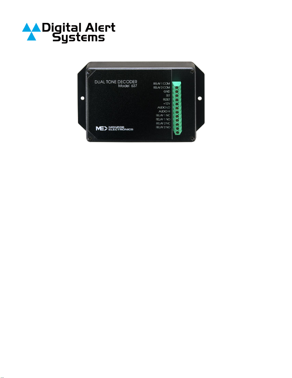
Digital Alert Systems Model 637
Tone Decoder allows switch
control via Cue Tones©.
Settings may be enabled for use
of 1 to 4 Cue Tones. The output
may be made to latch, toggle or
provide a momentary pulse.
Input levels may vary from
–24 to +6 dB of audio.
Please refer to the instruction
manual for the 3185E for specific
switch and control settings.
Installation
1. Remove the four screws on the
cover of the 637. Refer to the
model 3185E manual, and set
the jumpers for latching, toggling
or momentary, and the number
of digits to decode. Then set the
3 rotary switches to the code to
be decoded.
2. Connect the device(s) to be
controlled, to the common
(COMM) and the normal open
(NO) or the normally closed (NC)
–as desired –connections on
the terminal block.
3. The connections on the terminal
block for (RELAY 1) and (RELAY
2) are separate contacts, but are
part of the same relay.
4. The (SET) and (RESET)
connections are used as
described in the 3185E manual.
5. "AudioLo and AudioHi allow
connections of the audio
containing the DTMF tones to be
decoded. They may be
balanced or unbalanced, and
600 ohm impedance or high
impedance. Refer to the 3185E
manual for jumper settings":
6. Connect the power supply’s
white wire to the +12 V DC on
the 637, and the BLACK wire to
(GND).
7. Replace the board in the case,
and reinsert the screws to
secure the case top.
Specifications
Auto Input Impedance
Selectable 60010%
>10 Kbalanced/unbalanced
Audio Input Coupling
AC
Audio Input Level
45 mV p~p (-34 dBmV) to 13.8 V
p~p (+16 dBmV)
Audio Input Range
-24 dBmV to 6 dBmV: adjustable
10 dBmV
Digit Validation Time
40 mSec minimum
Inter-digit Time
40 mSec to 3 Sec
Set/Reset Inputs
>20 Sec to 3 Sec
Relay Output
DPDT; 2A @ 30 VDC
Power Requirement
100-240VAC, 50-60 HZ input/
12VDC output supplied.

CATV Switching and Control
585-765-2254 fax 585-765-9330
100 Housel Ave. | Lyndonville | NY | 14098
www.digitalalertsystems.com
WARRANTY
Digital Alert Systems, Inc. warrants to the owners, each instrument and sub-assembly manufactured by
them to be free from defects in material and workmanship for a period of two years after shipment from
factory. This warranty is applicable to the original purchaser only.
Liability under this warranty is limited to service, adjustment or replacement of defective parts (other than
fuses and batteries) on any instrument or sub-assembly returned to the factory for this purpose,
transportation charges prepaid.
This warranty does not apply to instruments or sub-assemblies subjected to abuse, abnormal operating
conditions, or unauthorized repair or modification.
Since Digital Alert Systems, Inc. has no control over conditions of use, no warranty is made, or implied as
to the suitability of our product for the customer's intended use.
THE WARRANTY SET FORTH IN THIS ARTICLE IS EXCLUSIVE AND IN LIEU OF ALL OTHER
WARRANTIES AND REPRESENTATIONS, EXPRESS, IMPLIED OR STATUTORY INCLUDING, BUT
NOT LIMITED TO THE IMPLIED WARRANTIES OF MERCHANTABILITY AND FITNESS. Except for
obligations expressly undertaken by Digital Alert Systems, in this warranty, Owner hereby waives and
releases all rights, claims and remedies with respect to any and all warranties, express, implied or
statutory (including without limitation, the implied warranties of merchantability and fitness), and including
but without being limited to any obligation of Digital Alert Systems with respect to incidental or
consequential damages, or damages for loss of use. No agreement or understanding varying or extending
the warranty will be binding upon Digital Alert Systems unless in writing signed by a duly authorized
representative of Digital Alert Systems.
In the event of a breach of the foregoing warranty, the liability of Digital Alert Systems shall be limited to
repairing or replacing the non-conforming goods and/or defective work, and in accordance with the
foregoing, Digital Alert Systems shall not be liable for any other damages, either direct or consequential.
RETURN POLICY TO FACTORY
Materials returned to Digital Alert Systems must have a Return Material Authorization number. To obtain a
RMA number, contact our A/V Switching & Control Customer Service at 585-765-2254 or fax 585-765-
9330. Customers have 30 days to determine that the product ordered fills their need and performs as
described in the applicable literature. Units returned for approved repair or credit, must be in the original
packaging including all parts and paperwork plus be in very good physical condition. If not, the customer
is billed the cost to refurbish the unit and for missing accessories and merchandise. No products may be
returned for change or credit after 12 months of the shipment date. Digital Alert Systems reserves the
right to repair or replace units under warranty.

3
Model 3185E
DUAL TONE DECODER
INSTRUCTION MANUAL
Digital Alert Systems
100 Housel Ave |Lyndonville |NY |14098 phone 585-765-2254 |fax
585-765-9330 digitalalertsystems.com
Printed in USA |Copyright© | Digital Alert Systems, Inc.
Specifications subject to change without notice
P/N 1340163
Version 1.20 03252019

4
TABLE OF CONTENTS
DESCRIPTION
5
SPECIFICATIONS
6
INSTALLATION
7
Mounting
7
Pin Numbers and Functions
7
Figure 1 –Edge Connector, Switch and Indicator Locations
8
Figure 2 –Block Diagram
8
Audio Input Connection
9
‘Set’Input Connection
9
‘Reset’Input Connection
9
Relay Output Connection
9
Power Supply Input
9
CUSTOMER OPTIONS
10
FIGURE 3 –Jumper Locations
11
Input Impedance
12
Input Balanced/Unbalanced
12
5 Minute Restoral
12
Momentary Output for ON and OFF
12
Output Relay
12
10 Second Pulse
12
Number of Digits to Decode
13
Fourth Digit ON/OFF
13
CODE SELECTION
14
OPERATION
14
Operating With a 4-Digit Code
14
Operating With a 3-Digit Code
15
Operating With a 2-Digit Code
15
Operating With a 1-Digit Code
15
ADJUSTMENT
15
WARRANTY AND RETURNS
16

5
DESCRIPTION
The Model 3185E Dual Tone Decoder is capable of accepting a sequence of up to four dual
tone signal inputs such as those from a Touch-Tone® telephone keypad. It provides a relay closure as
its output. Standard features include:
•Dual Form C Relay Output
•Selectable Input Impedance
•Selectable Balanced/Unbalanced Input
•Adjustable Input Signal Range
•Restoral of Output Status if Power Interruption is Less Than 5 Minutes.
•Selectable Momentary Output for ON and OFF sequences
•Digit Sequence Selectable up to Four Digits
•Selectable Relay Output Action (latching, momentary, or alternate).
•Level Sensitive 'Reset' Input
•Level Sensitive 'Set' Input

6
SPECIFICATIONS
Input Coupling ------------------------------------------------AC
Input Impedance:
Factory Setting -------------------------------------10 kΩMinimum
Selectable -------------------------------------------600ΩTerminated
Input: Factory Setting -------------------------------------Unbalanced
Selectable ------------------------------------------Balanced Common Mode
Range ------------------------------------------- -------± 5 Volts
Input Signal Range:
Minimum ---------------------------------------------50 mV p-p
Maximum --------------------------------------------1.5 V p-p
Input Range:
Nominal ----------------------------------------------14 dBm to -4 dBm
(155mV to 489 mV)
Optional ----------------------------------------------±10 dBm Adjustable Digit
Validation Time ----------------------------------------------40 ms Minimum
Inter-Digit Time:
Minimum ---------------------------------------------40 ms
Maximum --------------------------------------------3 Seconds
Maximum Digits Per Second:
No Twist ---------------------------------------------13
±6 dB -------------------------------------------------12
Relay Output --------------------------------------------------DPDT 30 VDC @ 2 Amp.
‘Reset’ Line ----------------------------------------------------Level Sensitive
Minimum 20 ms Pulse to
Ground.
‘Set’ Line -------------------------------------------------------Level Sensitive
Minimum 20 ms Pulse to
Ground.
Edge Connector ---------------------------------------------- Model 3000RK
(Cinch Jones 50-20A-30)
Power Requirements ---------------------------------------12 Volts D.C. ±10%
40 mA Maximum.
Physical Dimensions ----------------------------------------5.0 in.H x 3.0 in.W x 0.6 in.D

7
INSTALLATION
Mounting:
The Model 3185E is designed to plug into a Model 3000RK 20-pin edge connector. All connections are
intended to be made at the edge connector and will be referred to in this manual by edge connector
number or letter.
Pin Numbers and Functions:
Pin numbers are listed below for the Model 3185E when plugged into a 3000RK Connector. Consult
FIGURE 1 on page 4 for proper registration of pin numbers.
PIN NUMBER FUNCTION
1 Common terminal for relay output referenced to pins 9 and 10.
2 Circuit common (ground).
3 Circuit common (ground).
5 Audio input low (audio input circuit common if unbalanced).
6 Audio input high.
8 +12 Volt D.C. power supply input.
9 Normally closed contact for relay output referenced to pins 1 and 10.
10 Normally open contact for relay output referenced to pins 1 and 9.
A Common terminal for relay output referenced to pins K and L.
B Reserved. Connections to this pin will disable card.
D ‘Set’ input.
E ‘Reset’ input.
K Normally closed contact for relay output referenced to pins A and L.
L Normally open contact for relay output referenced to pins A and K.

8
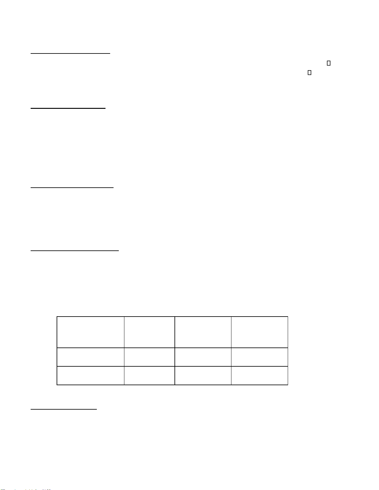
FIGURE 1 Edge Connector, Switch and Indicator Locations
and Modifications for 4 digit ON/OFF Operation
FIGURE 2 Block Diagram
9
Audio Input Connection:
The audio input is connected at pins '6' and '5' (circuit common). The 3185E is factory set at 10 k input
impedance; unbalanced. This audio input may be changed by the customer to have a 600 termination
instead of 10 kΩ, and also to be balanced instead of unbalanced. Consult the CUSTOMER OPTION
section for more explanation.
‘Set’ Input Connection:
The ‘Set’ input is connected at pin 'D', and when pulsed to circuit common will energize the output relay.
The output relay will remain energized until the proper 'OFF' code is received or the ‘Reset’ input is
pulsed to ground. This input is level sensitive and requires a minimum pulse width of 20 msec. to circuit
common to activate or de-activate the output relay. The ‘Set’ input has precedence over all functions
except ‘Reset’.
If the 3185E's ‘Set’ input is pulsed to circuit common while decoding a code sequence it will clear
previous valid digit(s) decoded after the ‘Set’ input returns to a ‘high’ state.
‘Reset’ Input Connection:
Momentarily connecting pin 'E' to circuit common will cause the 3185E to reset. This input is level
sensitive and requires a minimum pulse of 20 msec. to circuit common to reset the card. The ‘Reset’
input dominates over all other functions.
NOTE: The 3185E will ignore all commands or code sequences until the ‘Reset’ input is removed from
circuit common.
Relay Output Connections:
The 3185E provides a dual Form C relay output. The output relay will energize whenever the
preprogrammed 'ON' code sequence is received or the ‘Set’ input is momentarily connected to circuit
common. If the output relay is set to ‘momentary’, the output relay will activate approximately 40ms after
the last valid digit is received and stay on as long as the last valid digit is present. If the output relay is
set to ‘latching’, the output relay will remain energized until the programmed ‘OFF’ code sequence is
received or the ‘Reset’ input is momentarily connected to circuit common.
The dual Form C relay output connections are shown below:
RELAY OUTPUT
COMMON
CONTACT
NORMALLY
CLOSED
CONTACT
NORMALLY
OPEN
CONTACT
1 FORM C
1
9
10
1 FORM C
A
K
L
TABLE 1
Power Supply Input:
The power supply input is connected to pins '8' (+12 VDC) and '3' (circuit common). The 3185E requires
a power supply capable of providing 50mA minimum, and regulation of the +12 volt, ±10 %.

10
CUSTOMER OPTIONS
The Model 3185E is factory set to the following:
Input Impedance: 10 kΩ
Input: Unbalanced
5 Minute Restoral: Enabled
Momentary Output for ON and OFF: Disabled
Output Relay: Latching
4 Digit Decode Sequence
* for Fourth Digit 'ON'
# for Fourth Digit 'OFF
Jumpers are used to modify these options.
See FIGURE 3 on the next page.
11
NUMBER OF DIGITS
J6
J5
RELAY OUTPUT MODE
J3
J4
1
X
X
LATCHING
O
O
2
X
O
MOMENTARY
X
O
3
O
X
ALTERNATE
O
X
4
O
O
MOMENTARY OUTPUT
FOR BOTH ON & OFF
X
X
X= JUMPER INSTALLED O=
JUMPER REMOVED
R12 = INPUT SIGNAL LEVEL RANGE ADJUSTMENT
JUMPER
OPEN
SHORTED
INPUT IMPEDANCE
J2
10kΩ◼
600Ω
INPUT
TERMINATION
J1
BALANCED
UNBALANCED◼
5 MINUTE
RESTORAL
J7
ENABLED◼
DISABLED
MOMENTARY
OUTPUT FOR BOTH
ON & OFF
J3, J4
DISABLED◼
ENABLED
◼= FACTORY SETTING
FIGURE 3 Jumper Locations

12
Input Impedance:
Input impedance may be either 10 kΩor 600 Ω. The J2 jumper determines the input impedance of the
3185E. Install a jumper at position J2 to terminate the audio input in 600 Ω. Consult FIGURE 3 for the J2
jumper location.
Input Balanced/Unbalanced:
The input may be selected to be balanced or unbalanced. The J1 jumper determines whether the input
is balanced or unbalanced. Removing the short from J1 will make the input balanced. Consult FIGURE 3
for the J1 jumper location.
5 Minute Restoral:
The 3185E may be selected to restore the output status for a power interruption of less than five
minutes. The 3185E is factory set to enable this restoral. The J7 jumper is open. To disable the five
minute restoral install a jumper on J7. Consult FIGURE 3 for J7 location.
Momentary Output for ON & OFF:
This setting provides a momentary output relay activation for both the ON sequence and the OFF
sequence. Momentary duration is 1 second. To enable this feature, install both J3 and J4.
Output Relay:
The output relay on the 3185E may be set in three different modes of operation; latching, momentary or
alternate action (toggling). The 3185E is factory set to latching.
Being set at latching means the output relay will energize when the pre-programmed 'ON' code is
received or the ‘Set’ input is momentarily connected to circuit common. The output relay will remain
energized until the preprogrammed 'OFF' code is received or the ‘Reset’ input is momentarily connected
to circuit common.
When the output relay is programmed to operate in the momentary mode, it will energize for the duration
that the last valid digit is present. In the momentary mode the 3185E will not respond to its pre-
programmed 'OFF' code.
Alternate action programs the relay for latching (toggling) relay output. In this mode the output relay
energizes and de-energizes with the same pre-programmed 'ON' code sequence.
10 Second Pulse:
If both ‘Set’ and ‘Reset’ are low and the relay mode is ‘momentary’, then when a valid ‘ON’ sequence of
digits is received, the relay is turned on for 10 seconds then ‘OFF’ – even if the last tone is still present.
The decoder will ignore all tones and ‘Set’ and ‘Reset’ activities during the 10-second period. Applies
only to firmware version 80154-1.10 and later.
13
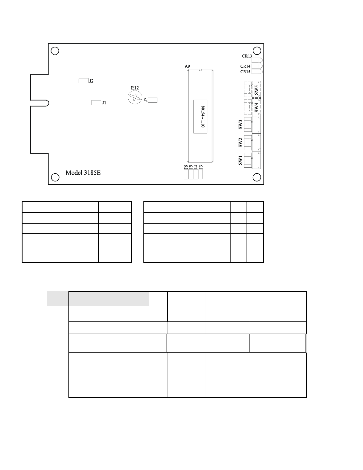
The programming of jumpers for the output relay is shown below. Consult FIGURE 3 page 7 for the 'J3'
jumper and the 'J4' jumper location.
RELAY OUTPUT
MODE
JUMPER
J3
J4
LATCHING
O
O
MOMENTARY
X
O
ALTERNATE
O
X
MOMENTARY
OUTPUT FOR BOTH
ON & OFF
X
X
TABLE 2
X = JUMPER INSTALLED
O = JUMPER REMOVED
Number of Digits to Decode:
The 3185E is factory set to decode a 4-digit 'ON' code sequence and a 4-digit 'OFF' code sequence.
The first three digits of the code sequence are the same for both 'ON' and 'OFF'. The fourth digit for the
'ON' code sequence is factory set to '*', and the fourth digit for the 'OFF' code sequence is factory set to
'#'. The number of digits to decode is determined by jumpers 'J6' and 'J5'. Consult FIGURE 3 page 7 for
the location of 'J6' and 'J5'.
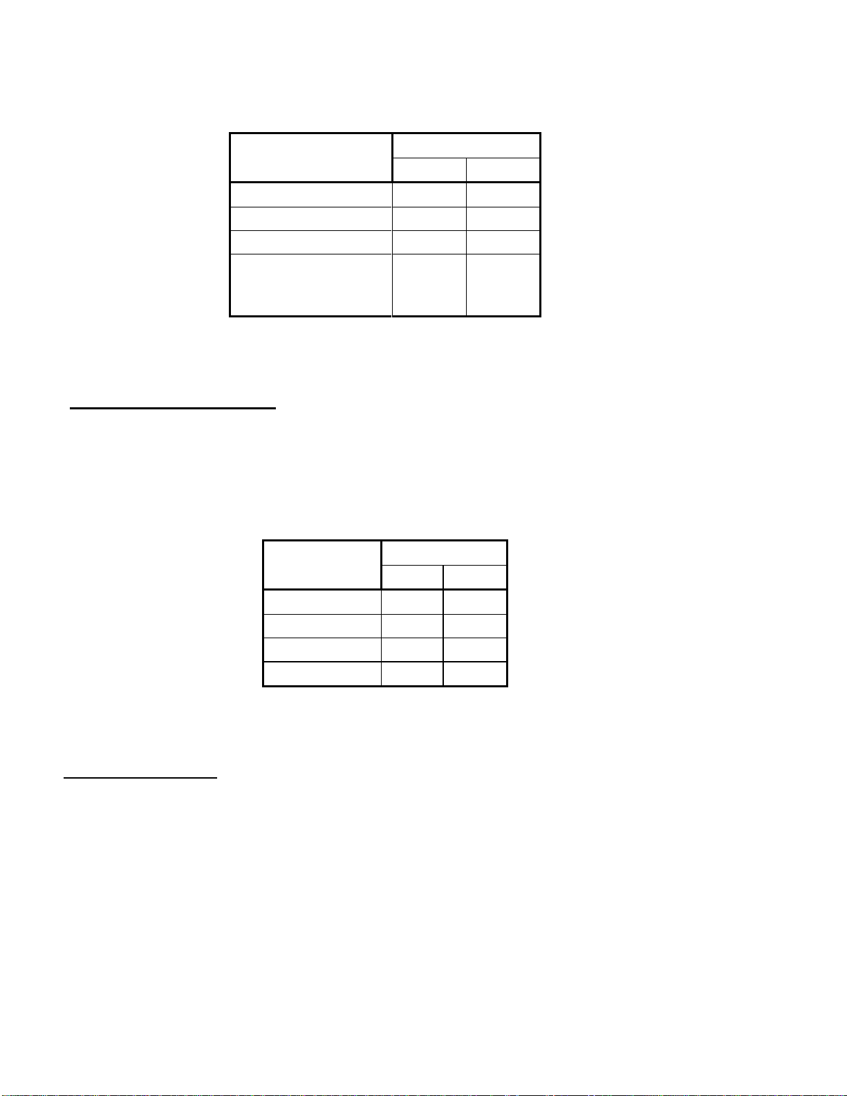
The programming of jumpers for the number of digits to decode is shown below:
NUMBER OF
DIGITS
JUMPER
J6
J5
1
X
X
2
X
O
3
O
X
4
O
O
TABLE 3
X = JUMPER INSTALLED
O = JUMPER REMOVED
Fourth Digit ON/OFF:
The fourth digit of the 'ON' code sequence and the fourth digit of the 'OFF' code sequence are factory
set at '*' and '#' respectively. To enable user selection of the fourth digits, it is necessary to remove
resistor ‘R8” and install two additional selection switches, S4 and S5, plus IC A3. When ordering the
switches, please use Digital Alert Systems part number ‘9200002’ for each of the two switches and part
number ‘9120375’ for the IC required.
Consult the PC board layout in Figure 1, on Page 4, for the location of the parts to be removed and
inserted.

14
CODE SELECTION
The hexadecimal rotary switches on the front edge of the 3185E determine each digit in the code
sequence. 0 through D select the corresponding DTMF digit to be decoded. The letter 'E' on the rotary
switch represents the '*' DTMF digit and the letter 'F' on the rotary switch represents the '#' DTMF digit.
As stated before, the 3185E is factory set to decode a 4-digit 'ON' code sequence and a 4-digit 'OFF'
code sequence. The first three digits of the code sequence are the same for 'ON' and 'OFF' commands.
The fourth digit for the 'ON' code sequence is factory set to '*', and the fourth digit for the 'OFF' code
sequence is factory set to '#'.
It is not necessary to power down the 3185E when you are programming the code sequence. The 3185E
program will read the switch settings each time a code sequence is received.
Consult FIGURE 1 on page 4 for location of switches and their designations.
OPERATION
When the 3185E is connected to a DC power source, the Power/Valid Digit LED CR14 on the front edge
of the PC board will be illuminated. This LED indicator will continue to illuminate until a valid DTMF digit
is detected or DC power is removed from the board.
The Valid Sequence LED CR15 will illuminate upon the decoding of a correct DTMF code tone pair in
the proper sequence. Upon the fourth correct digit, the output relay activates and the Relay Output LED
CR13 illuminates.
During the reception of valid DTMF tone pairs in a sequence the 3185E will —after decoding a valid
code number —wait for the next valid code in the sequence. If the time between digits is more than 3
seconds, the 3185E will reset and require that the sequence be sent completely again.
Operating With a 4-Digit Code:
When a 4-digit code sequence is selected on the 3185E the switch program will be as follows:
SWITCH 1 = first digit of the code sequence for both 'ON' and 'OFF'.
SWITCH 2 = second digit of the code sequence for both 'ON' and 'OFF'.
SWITCH 3 = third digit of the code sequence for both 'ON' and 'OFF'.
SWITCH 4 = fourth digit of the code sequence for 'ON' (preset to '*' if switch not installed).
SWITCH 5 = fourth digit of the code sequence for 'OFF' (preset to '#' if switch not installed).
If the 3185E is programmed for momentary relay output or alternating relay action SWITCH 5 is not used
for programming.

15
Operating With a 3-Digit Code:
When a 3-digit code sequence is selected on the 3185E the switch program will be as follows:
SWITCH 1 = first digit of code sequence for both 'ON' and 'OFF'.
SWITCH 2 = second digit of code sequence for both 'ON' and 'OFF'.
SWITCH 3 = third digit of code sequence for 'ON'.
SWITCH 4 = third digit of code sequence for 'OFF' (preset to '*' if switch not installed).
If the 3185E is programmed for momentary relay output or alternating relay action SWITCH 4 is not used
for programming.
Operating With a 2-Digit Code:
When a 2-digit code sequence is selected on the 3185E the switch program will be as follows:
SWITCH 1 = first digit of code sequence for both 'ON' and 'OFF'.
SWITCH 2= second digit of code sequence for 'ON'.
SWITCH 3 = second digit for code sequence for 'OFF'.
If the 3185E is programmed for momentary relay output or alternating relay action SWITCH 3 is not used
for programming.
Operating With a 1-Digit Code:
When a 1-digit code sequence is programmed into the 3185E the switch program is as follows:
SWITCH 1 = first digit of code sequence for 'ON'.
SWITCH 2 = first digit of code sequence for 'OFF'.
If the 3185E is programmed for momentary relay output or alternating relay action SWITCH 2 is not used
for programming.
ADJUSTMENT
Potentiometer R12 permits the user to adjust the level of the received DTMF tones. This adjustment
would be made when the received audio levels are too low or too high to permit reliable decoding.
Setting R12 fully counterclockwise will provide -10 dBmV of gain. Setting R12 fully clockwise will provide
+10 dBmV of gain.
Consult FIGURE 3 on page 7 for the location of potentiometer R12.

16
WARRANTY
Digital Alert Systems, Inc. warrants to the owners, each instrument and sub-assembly manufactured by
them to be free from defects in material and workmanship for a period of two years after shipment from
factory. This warranty is applicable to the original purchaser only.
Liability under this warranty is limited to service, adjustment or replacement of defective parts (other than
fuses and batteries) on any instrument or sub-assembly returned to the factory for this purpose,
transportation charges prepaid.
This warranty does not apply to instruments or sub-assemblies subjected to abuse, abnormal operating
conditions, or unauthorized repair or modification.
Since Digital Alert Systems, Inc. has no control over conditions of use, no warranty is made, or implied as
to the suitability of our product for the customer's intended use.
THE WARRANTY SET FORTH IN THIS ARTICLE IS EXCLUSIVE AND IN LIEU OF ALL OTHER
WARRANTIES AND REPRESENTATIONS, EXPRESS, IMPLIED OR STATUTORY INCLUDING, BUT
NOT LIMITED TO THE IMPLIED WARRANTIES OF MERCHANTABILITY AND FITNESS. Except for
obligations expressly undertaken by Digital Alert Systems, in this warranty, Owner hereby waives and
releases all rights, claims and remedies with respect to any and all warranties, express, implied or
statutory (including without limitation, the implied warranties of merchantability and fitness), and including
but without being limited to any obligation of Digital Alert Systems with respect to incidental or
consequential damages, or damages for loss of use. No agreement or understanding varying or extending
the warranty will be binding upon Digital Alert Systems unless in writing signed by a duly authorized
representative of Digital Alert Systems.
In the event of a breach of the foregoing warranty, the liability of Digital Alert Systems shall be limited to
repairing or replacing the non-conforming goods and/or defective work, and in accordance with the
foregoing, Digital Alert Systems shall not be liable for any other damages, either direct or consequential.
RETURN POLICY TO FACTORY
Materials returned to Digital Alert Systems must have a Return Material Authorization number. To obtain a
RMA number, contact our A/V Switching & Control Customer Service at 585-765-2254 or fax 585-765-
9330. Customers have 30 days to determine that the product ordered fills their need and performs as
described in the applicable literature. Units returned for approved repair or credit, must be in the original
packaging including all parts and paperwork plus be in very good physical condition. If not, the customer
is billed the cost to refurbish the unit and for missing accessories and merchandise. No products may be
returned for exchange or credit after 12 months of the shipment date. Digital Alert Systems reserves the
right to repair or replace units under warranty.
Table of contents
Other Digital Alert Systems Media Converter manuals


