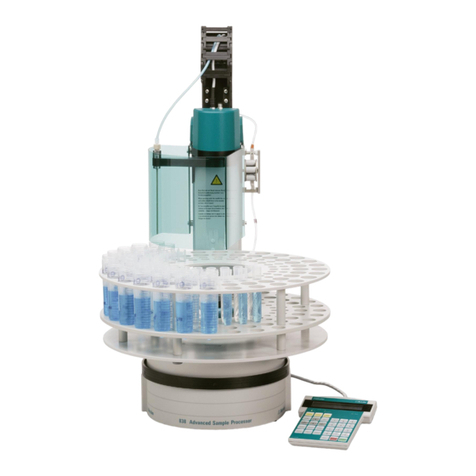
Metrohm 789 Reference manual

CH-9101 Herisau/Switzerland
www.metrohm.com
789 Robotic Sample Processor XL
778 Sample Processor
Program version 5.789.0020
and 5.778.0020
Short Introduction
and Tutorial
8.789.1023 02.2004 / dm

Contents
II Metrohm 778/789 Sample Processor,Contents
Teachware
Metrohm AG
Oberdorfstr. 68
CH-9100 Herisau
These instructions are protected by copyright. All rights reserved.
Although all the information given in these instructions has been checked with great
care, errors cannot be entirely excluded. Should you notice any mistakes, please in-
form the author at the address given above.
© Metrohm AG 2004
Printed in Switzerland

Contents
Metrohm 778/789 Sample Processor,Contents III
Table of Contents
1Introduction 1
1.1 Overview ............................................................................................1
1.1.1 Overall view ................................................................................................2
1.1.2 Sample racks .............................................................................................3
1.2 Rear panel..........................................................................................4
1.3 Electrical connections.......................................................................5
1.4 Installing accessories .......................................................................6
1.5 Installing a 786 Swing Head .............................................................6
1.6 Keypad ...............................................................................................7
2Operation 8
2.1 Preliminary remarks ..........................................................................8
2.2 Switching and initialising ..................................................................8
2.3 Configuring lift positions and rack data ....................................... 10
2.4 Configuring lift and robotic arm .................................................... 13
2.5 Moving rack and lift........................................................................ 15
3Methods 20
3.1 Processing methods ...................................................................... 20
3.2 Creating a new method .................................................................. 25
4Executing a series of samples 30
4.1 Standard method "Titrino".............................................................. 30
5Index 33

Contents
IV Metrohm 778/789 Sample Processor,Contents
List of Illustrations
Figure 1 Overall view................................................................................................................. 2
Figure 2 Rear panel ..................................................................................................................4
Figure 3 Connection panel ....................................................................................................... 5
Figure 4 Keypad........................................................................................................................ 7

1.1 Overview
Metrohm 7778/789 Sample Processor,Introduction 1
1 Introduction
This tutorial describes initial steps when using a Sample Processor. It in-
troduces you to the most important operating controls and work steps
required for processing series of samples.
1.1 Overview
A brief overview is intended to familiarize you with the most important
features of a Sample Processor.
Please refer to the detailed Instructions for Use of the Sample Proces-
sor for the procedures for installing the individual components and ac-
cessories.
This will be followed by a brief overview of purpose and mode of opera-
tion of the most important components of the instrument.

1.1 Overview
2 Metrohm 778/789 Sample Processor,Introduction
1.1.1 Overall view
Figure 1 Overall view
1Tubing and electrode cables are laid in the guide chain.
2It is absolutely essential that the safety shield which also serves
as a splash protection is attached. This is the only way of elimi-
nating the risk of injury when operating the Sample Processor.
Safety shields are available in various designs.
3The sample rack is detachable. Sample racks with optimized ar-
rangement and various numbers of positions are available for an
extremely wide variety of vessel sizes. The various types of sample
racks are detected automatically by the Sample Processor when
you press the <RACK> key.
4Magnetic stirrers (model 741) or other accessories, such as stand
supports (6.2001.070), can be attached to the stirrer rail.
5A 786 Swing Head with a robotic arm can be mounted on any lift
in place of a titration head. This allows you to use even multi-row
sample racks and extends the scope of application of the Sample
Processor since a robotic arm also allows positions outside the
rack to be reached. Various robotic arms are available for various
applications.
6Electrodes, dosing tips, rod stirrers and other accessories can be
attached in the titration head.
1
2
3
4
6
7
8
5

1.1 Overview
Metrohm 7778/789 Sample Processor,Introduction 3
7 A Sample Processor is available as a single-tower or twin-tower
model, each with one lift per tower. Different working positions and
shifting positions etc. can be predefined for each lift, depending on
sample rack or vessel size. Depending on requirements, various ti-
tration heads can be mounted on the titration head holder. It is
also possible to install a Swing Head drive (Model 786) with robotic
arm on the lift, see 5.
8 The beaker sensor (infrared sensor) on the front side of the tower
is able to detect the presence of a sample vessel. This allows to
prevent "flooding" if a vessel is missing. If a 786 Swing Head is
used, a robotic arm with touch sensor is able to perform this task.
The behaviour of the Sample Processor if a vessel is missing can
be defined.
1.1.2 Sample racks
Various types of sample racks are available for the Sample Processor
Models 778 and 789.
• Sample racks with 42 cm diameter can be used for all Sample
Processor models. A 786 Swing Head with robotic arm is required
on the 789 Robotic Sample Processor XL.
• Sample racks with 48 cm diameter are suitable only for the 789 Ro-
botic Sample Processor XL with 786 Swing Head.
The various sample racks also differ in respect of the number, ar-
rangement and diameter of the sample positions on the rack. Please re-
fer to the Instructions for Use of your instrument for a list of available
standard sample racks.
Each rack features a type-specific
magnetic code allowing a Sample
Processor to automatically detect the
type of rack attached.
The adjacent drawing indicates how to
fit a sample rack onto the turntable.
Then press the <RACK> key on the
keypad to initialize the sample rack.
The instruments are able to detect the
magnetic code (the coding of the rack
type) in initial position.
Magnet sensor
Magnet holder

1.2 Rear panel
4 Metrohm 778/789 Sample Processor,Introduction
1.2 Rear panel
The rear panel of the Sample Processor may have a differing arrangement,
depending on the model. The rear panel of the standard model 2.778.0010,
with one tower, a membrane pump and a connection for an external pump is
shown below.
WARNING-FireHazard-
withthesametypeandratingoffuse
Forcontinuedprotectionreplaceonly
Made by Metrohm
Herisau Switzerland
S: 115 VA U : 100 - 240 V f: 50 - 6 0 Hz
RS 232
MSB1
MSB3
MSB2
Power Keyboard
Remote
Ext.
Pump 2
Swing
Head
Pump 1
Figure 2 Rear panel
9 If you wish to use the pump 1 for rinsing electrodes and tubing,
connect the tubing to the rinsing nozzles on the manifold.
10 The built-in pumps are membrane pumps. They are suitable for
rinsing with spray nozzles and for aspirate processed aqueous
sample solutions by suction. If you intend to use organic solvents or
9
10
11
12
13
14
15

1.3 Electrical connections
Metrohm 7778/789 Sample Processor,Introduction 5
aspirate aqueous samples with solid components (precipitations)
by suction, you must connect a peristaltic pump.
11 The electrical valve ensures that no fluid is able to drip when rinsing
or aspirating by suction.
12 A rod stirrer (e.g. model 802) or a magnetic stirrer (model 741) can
be connected to the stirrer connection.
13 All electrical connections are located on the rear panel of the
Sample Processor. They are protected against spilled fluid.
14 An additional pump (e.g. a peristaltic pump, model 772) can be
connected to the external pump connection.
15 If a Swing Head drive is connected to the corresponding connec-
tion socket, it is detected automatically by the Sample Processor.
1.3 Electrical connections
The electrical connections are the same on all models of the 778/789
Sample Processors.
WARNING-FireHazard-
withthesametypeandratingoffuse
Forcontinuedprotectionreplaceonly
Made by Metrohm
Herisau Switzerland
S: 115 VA U : 100 - 240 V f: 50 - 60 H z
RS 232
MSB1
MSB3
MSB2
Power Keyboard
Remote
Figure 3 Connection panel
16 The power switch ('Power') for switching the instrument on and
switching it off is located on the instrument rear panel, as are the
electrical connections, for reasons relating to safety.
17 Keyboard connection. Press the plug firmly together at the sides
in order to disconnect the cable.
18 Various Metrohm devices can be connected to the three MSB
sockets. The 801 Magnetic stirrer and the dosing drives 805 Dosi-
mat and 800 Dosino are best suited for this. If an 801 Magnetic stir-
rer is connected to an MSB socket, a dosing drive of one of the
types mentioned can also be attached to its MSB connector. This
means that only one MSB socket is used to control various periph-
eral devices (daisy chain).
16
17 18 19 20 21

1.4 Installing accessories
6 Metrohm 778/789 Sample Processor,Introduction
The 685 Dosimat and the 700 Dosino can also be connected to an
MSB socket but not with the combined configuration mentioned
above.
19 Metrohm titrators (e.g.: Titrinos) or other instruments which can be
controlled via remote signals can be connected to the remote in-
terface.
20 The serial RS232 port is used for data transmission if the Sample
Processor is controlled with the aid of a computer software for in-
stance.
21 Mains connection. The power supply to the Sample Processor is
best connected via the supplied mains cable which is connected to
a mains distributor.
1.4 Installing accessories
Install all the accessories required for your work on the Sample Proc-
essor. The Instructions for Use provide you with all information required
for this.
In order to perform the exercises in this brief introduction, you will re-
quire only the keypad and any sample rack with a few appropriate
sample vessels. If you have available a titrator from the Metrohm Titrino
series, please connect both units with the remote cable (6.6.2141.020).
Plug the cable into each Remote socket on the instrument's rear panel.
1.5 Installing a 786 Swing Head
If your system has a Swing Head drive with robotic arm, please install it
in accordance with the Instructions for Use of the 786 Swing Head
(Chapter 2 Installation) and connect the cable to the 'Swing Head'
socket on the rear panel of the Sample Processor's tower.
Please always comply with the following sequence:
1. Mount and connect the Swing Head drive with the instrument
switched off.
2. Switch on the instrument, press the <CONFIG> key and keep it
pressed. Then configure the robotic arm data.
3. Mount the robotic arm.

1.6 Keypad
Metrohm 7778/789 Sample Processor,Introduction 7
1.6 Keypad
A brief overview of the key functions in manual mode of the Sample
Processor is provided below.
Controller
*
*
*
*
*
*
*
*
c
o
u
n
t
e
r
1
/
1
2
P
U
M
P
-
-
-
-
S
T
I
R
-
-
-
-
r
e
a
d
y
T
O
W
E
R
1
T
O
W
E
R
2
L
E
A
R
N
C
O
N
F
I
G
P
A
R
A
M
U
S
E
R
H
O
M
E
E
N
D
I
N
S
E
R
T
T
O
W
E
R
S
E
L
E
C
T
R
E
S
E
T
C
L
E
A
R
D
E
L
E
T
E
Q
U
I
T
E
N
T
E
R
S
A
M
P
L
E
M
O
V
E
L
I
F
T
P
U
M
P
S
T
I
R
D
O
S
S
C
A
N
C
T
R
L
W
A
I
T
D
E
F
<
P
R
I
N
T
RACK
H
O
L
D
L
E
A
R
N
6.2142.040
>
M
E
T
H
O
D
S
T
O
PS
T
A
R
T
Me
t
r
o
h
m
-
+
PREV
NEXT
-
Figure 4 Keypad
Please work through the following chapter to familiarize yourself with the
procedures for operating the Sample Processor.
Sample
counter
Method name
Status line
Active tower
Menu keys
Lift and rac
k
operation
Editing keys
Command ke
y
s
Sequence
control

2.1 Preliminary remarks
8 Metrohm 778/789 Sample Processor,Operation
2 Operation
2.1 Preliminary remarks
Depending on model (single-tower or twin-tower model) and equipment
(with or without Swing Head) of the Sample Processor, the procedures
for operating the instrument may differ slightly. What is said below de-
scribes operation of a twin-tower model with Swing Head drive and ro-
botic arm.
On a single-tower model, there is no selection of the active tower; thus,
the <SELECT> key does nothing in manual mode. If no Swing Head is
mounted, no external position can be reached.
2.2 Switching and initialising
Please first detach the sample rack from the Sample Processor in order
to demonstrate the procedure for rack detection. Switch the instrument
off.
1
Mains switch
on
Switching on
Operate the mains switch to switch on the Sample Processor. The
mains switch is located on the instrument rear panel at the far right.
If a Swing Head drive with robotic arm is mounted, the robotic arm will
swing first towards the centre of the rack and adjust its initial position
(0° axis). The robotic arm will then be swivelled fully out. The turntable
of the Sample Processor then starts to turn, also serving the purpose of
adjustment. When doing this, the instrument is attempting to detect the
type of mounted rack.
+Sample counter
******** counter 0/0
PUMP----STIR-- ready (Display of initial status
The status of the sample counter 0 of 0 indicates that no rack has been
detected. In this status, it is not possible to move the turntable since no
rack data is available.

2.2 Switching and initialising
Metrohm 7778/789 Sample Processor,Operation 9
2
<CONFIG>
<ENTER>
Setting the dialog language
If you wish to set a dialog language other than English, you can set this
language easily.
Press the <CONFIG> key and then press <ENTER>.
>auxiliaries
dialog: english
(Language selection
<SELECT>
<ENTER>
<QUIT>
<QUIT>
Select german, french or spanish with the <SELECT> key and con-
firm your selection with <ENTER>.
Pressing <QUIT> twice returns to display of the initial status.
This tutorial is written in English. This is why you should set the dialog
language back to English.
3
<RACK>
Initialising the rack
Put on a sample rack. Turn it so that the Metrohm logo on the rac
k
points towards the tower or towards the centre between the towers (in
the case of a twin-tower model). The rack must lock into position when
mounted.
Press the <RACK> key on the keypad so that the rack is detected.
The rack will be rotated again (possibly after initialization of the Swing
Head). As soon as the rack is in initial position, the rack's magnetic
code is determined and the corresponding position table in the instru-
ment is activated.
+Sample counter
******** counter 0/12
PUMP----STIR-- ready
The sample counter displays 0 of 12 or another value depending on
the number of available sample positions on the sample rack.
Whenever you put on a rack other than that which was mounted on the
Sample Processor, always press the <RACK> key or switch the in-
strument off and back on again.

2.3 Configuring lift positions and rack data
10 Metrohm 778/789 Sample Processor,Operation
2.3 Configuring lift positions and rack data
1
<RACK>, <Î>
<CONFIG>
Setting lift positions
Before working with the Sample Processor, you should make a few im-
portant basic settings. These include lift positions or rack positions for
special beakers.
Put on a rack with sample vessels and initialize it with <RACK>. Turn
the rack to reach a valid sample position with the arrow key <Î>.
Press key <CONFIG>.
configuration
>auxiliaries (Configuration menu
Choose the >rack definitions sub-menu. In order to this, press the
arrow key <Ð>until you see the following display.
configuration
>rack definitions
(Edit rack data
<ENTER> Press <ENTER>.
>rack definitions
>>recall rack
(Load rack data
<ENTER> Press <ENTER>.
>>recall rack
name: 6.2041.310
(Rack selection
<ENTER>
The designation (order number) of the mounted rack is displayed. It is
also possible at this point to select from the stored standard racks with
<SELECT>.
Press <ENTER>.
>>recall rack
code 000001
(Display or change the rack code
<Ð>
This is the magnetic code of the rack, i.e. the arrangement of the mag-
netic pins on the underside of the sample rack. This six-digit code
serves to detect the rack.
Press <Ð>.
>>recall rack
work position T1 0 mm
(Working height of the lift on tower 1
<LEARN>
This is the working height of the lift, i.e. the lift position at which the ac-
tual determination process is to be performed. The position can either
be entered in mm (measured as of the upper stop position of the lift) or,
more conveniently, it can be set with the so-called LEARN function.
Press <LEARN>.

2.3 Configuring lift positions and rack data
Metrohm 7778/789 Sample Processor,Operation 11
>>recall rack
press Çor Èor ENTER
(Manual lift operation
<Ï> , <Ð>
<ENTER>
You can operate the lift with the arrow keys. Set the position of the lift
so that the titration head on the lift with electrodes and dosing tips is
immersed in a sample vessel. When you have set the position, press
<ENTER>.
>>recall rack
work position T1 101 mm
(Set working height
<ENTER>
The set lift position is displayed and can still be corrected if necessary.
Press <ENTER>.
>>recall rack
work position T2 0 mm
(Working height of the lift on tower 2
<LEARN>
<Ï> , <Ð>
<ENTER>
The working height of lift 2 can be set only if you have a twin-tower
model of a Sample Processor. Proceed as described above.
>>recall rack
rinse position T1 0 mm
(Rinsing height of the lift on tower 1
<LEARN>
<Ï> , <Ð>
<ENTER>
This is the height of the lift scheduled for rinsing. The position can also
be entered at this point manually in mm or it can be set with the
LEARN function, see above
>>recall rack
shift position T1 0 mm
(Shifting height of the lift on tower 1
<LEARN>
<Ï> , <Ð>
<ENTER>
This is the minimum height of the lift required when the rack is rotated.
The position can be entered manually in mm or set with the LEARN
function, see above.
>>recall rack
special pos. T1 0 mm
(Special height of the lift on tower 1
<LEARN>
<Ï> , <Ð>
<ENTER>
This is a further, freely defined height of the lift which can be used for
any purpose. The position can be entered manually in mm or set with
the LEARN function, see above.
>>recall rack
beaker radius * mm
(Radius of the sample beakers
<Ð>
This is where you can enter the radius of the sample beakers so that
the Sample Processor can check whether the size of the sample beak-
ers is suitable for processing with a titration head.
The default "*" indicates no specific beaker radius. Retain the setting.
Press <Ð>.
>>recall rack
beakersensor Tower
(Selection of the beaker sensor
The Sample Processor is able to automatically detect whether a sample
vessel is present at the current rack position. Two different types of
sensors are available. An optical IR sensor allowing larger vessels in
front of the tower to be detected by reflection is installed in each tower
of the Sample Processor. If using a 786 Swing Head, it is possible to

2.3 Configuring lift positions and rack data
12 Metrohm 778/789 Sample Processor,Operation
<SELECT>
<ENTER>
install a robotic arm with piezo-resistive sensor. This touch-sensitive
sensor detects a sample vessel by the process of lowering the robotic
arm on the rim of the vessel (in working position).
Select the tower sensor with the <SELECT> key and press <EN-
TER>.
>>recall rack
rack offset 0.00°
(Correct the angle of rotation
<Ð>
The rack offset offers the option of correcting the angle of rotation of
the rack. This is normally not required.
Press <Ð>.
>>recall rack
>>>special positions
(Define special positions on the rack
<ENTER>
The Sample Processor offers the option of reserving positions for spe-
cial vessels (e.g. rinsing beakers) on the sample rack. Up to 16 such
special beaker positions are possible.
Press <ENTER>.
>>>special positions
special beaker 1
(Number of the special beaker
<1>
<ENTER>
Enter the number of the special beaker to which you wish to assign a
rack position at this point.
Press <1> and <ENTER>.
>>>special positions 1
rack position 12
(Rack position of special beaker 1
<12>
<ENTER>
Whenever possible, choose the highest rack positions on the rack for
special beakers.
Enter <12> and press<ENTER>.
>>>special positions 1
work position T1 0 mm
(Working height of lift 1 for special beaker 1
...
We now move on to the various settings, such as working height and
beaker radius etc., which apply exclusively to this special beaker posi-
tion. Each special beaker may have its own settings.
Enter the corresponding data as you did beforehand for the sample
positions (see above).
After selecting the beaker sensor, you are prompted to overwrite the ex-
isting rack data.
>>>special positions 1
overwrite 6.2041.310 ?
(Confirm change of rack data
<ENTER>
<QUIT>
<QUIT>
Accept the new setting with <ENTER>. If you do not wish to accept
the new settings, press <QUIT>.
Press <QUIT> to quit , the Configuration menu.

2.4 Configuring lift and robotic arm
Metrohm 7778/789 Sample Processor,Operation 13
The new settings come into effect only when the rack is initialized.
<RACK> Press <RACK>.
2.4 Configuring lift and robotic arm
1
<SELECT>
<Í>, <Î>
<CONFIG>
<Ð>
tower 1
<ENTER>
Lift settings
There are two safety settings for each lift which you should make before
working with the Sample Processor. If you have mounted a 786 Swing
Head drive, you must define additional settings for control of the robotic
arm.
It is assumed that you have made the basic configuration of Swing
Head and robotic arm when they were installed; see Instructions for
Use for the 786 Swing Head.
Use <SELECT> to choose the tower on which you wish to make set-
tings and turn the rack to a valid rack position by pressing one of the
keys <Í>or <Î>for instance.
Press the <CONFIG> key and choose sub-menu tower 1 or tower 2.
configuration
>tower 1 (Configuration menu
<ENTER> Open this sub-menu with <ENTER>.
>tower 1
max. stroke path 235 mm
(Lowest lift position
<LEARN>
<Ð>
<ENTER>
The maximum stroke path defines how far the lift is allowed to move
down. This is a safety setting intended to prevent glass breakage on
electrodes or other damage owing to the lift.
On the one hand, you may enter a value in mm at this point or, on the
other hand, it is possible to use the LEARN function.
Press <LEARN> and carefully move the lift downwards with the <Ð>
key. When the lift reaches the lowest possible position for the rack, ac-
cept this position with <ENTER>.
>tower 1
min. beak. radius * mm
(Minimum permitted beaker radius
<Ð>
The minimum beaker radius is a further safety setting which should be
selected so that the items on the titration or transfer head on the tower
can still be immersed safely in a sample vessel.
The standard setting "*" means that this function is switched off. Do not
change this setting for the time being.
Advance with <Ð>.

2.4 Configuring lift and robotic arm
14 Metrohm 778/789 Sample Processor,Operation
>tower 1
>>Swing Head 1
(Settings of the Swing head and the robotic arm
<ENTER> Open the Swing Head 1 sub-menu with <ENTER> if you have
mounted a Swing Head with robotic arm.
>>Swing Head 1
rinse position 0 mm
(Rinsing height for external positions
<LEARN>
<Ð> <Ï>
<ENTER>
The following settings apply for external positions which can be
reached with the robotic arm in spite of the rack type.
The rinsing height can be set with the LEARN function. Press
<LEARN> and use keys <Ð>and <Ï>to set the required height.
Confirm with <ENTER>.
>>Swing Head 1
shift position 0 mm
(Shifting height for external positions
<LEARN>
<Ð> <Ï>
<ENTER>
The shifting height is the lift position which must be complied with if you
move from one external position to another external position. You can
set this with the LEARN function, as you can the rinse position, see
above.
>>Swing Head 1
external pos.1 84.00°
(Swing angle for external position 1
<LEARN>
<Í> <Î>
<ENTER>
You can now set the first of four possible external positions of the ro-
botic arm (swing angle and working height).
All settings for the external positions can be set with the LEARN func-
tion, see above.
>>Swing Head 1
work position 1 0 mm
(Working height for external position 1
<LEARN>
<Ð> <Ï>
<ENTER>
The working height can be set separately for each external position of
the robotic arm.
Use the LEARN function for this.
Configuration
>tower 2
(Configuration menu
<QUIT>
After the settings have been made for all external positions, you will re-
turn to the configuration menu where you can make further settings.
Press <QUIT> to quit the configuration menu.

2.5 Moving rack and lift
Metrohm 7778/789 Sample Processor,Operation 15
2.5 Moving rack and lift
1
<TOWER/
SELECT>
Selecting the tower
On a twin-tower model of a Sample Processor, the functions presented below
each refer to one of the two lifts.
Using the <TOWER/SELECT> key, you can switch over from tower 1 to
tower 2 and vice versa. The LEDs TOWER 1 and TOWER 2 on the keypad in-
dicate the selected tower.
●
●TOWER 1 ●
●TOWER 2 (Active tower 2
2
<Í/NEXT>
<Î/PREV>
<MOVE>
Moving the rack
The sample rack is still in initial position after the rack has been initialized (or
after being switched on). This is generally not a valid rack position.
Press keys <Í/NEXT> or <Î/PREV>. This turns the rack so that the next
rack position up or down stops in front of the active tower. If a Swing Head is
installed, the robotic arm is moved automatically to the centre of the rack posi-
tion.
Note the numbering of the rack positions.
If you wish to approach a specific rack position, press the command key
<MOVE>.
manual operation
MOVE 1 :sample
(Select the rack position
*Active tower
10
<ENTER>
<SAMPLE>
Enter the number of any rack position, e.g. 10, and press <ENTER>. The di-
rection of rotation of the rack is automatically selected by the Sample Proces-
sor so as to ensure the shortest possible path.
Further options for operating the rack include approaching the current sample
beaker or a special beaker. The current sample is defined by a counter which
is used for an automatic sequence. This counter can be set as required.
Press key <SAMPLE>.
manual operation
SAMPLE = 5
(Set SAMPLE variable
5
<ENTER>
<MOVE>
Enter any value, e.g. 5and press <ENTER>.
You can enter a new rack position with the command key <MOVE>.

2.5 Moving rack and lift
16 Metrohm 778/789 Sample Processor,Operation
manual operation
MOVE 1 :sample
(Select the rack position with <SELECT>
<SELECT>
<CLEAR>
sample
<ENTER>
<MOVE>
spec.1
<ENTER>
<MOVE>
Ext.1
<ENTER>
Instead of pressing the key <SELECT> several times, you can also use the
<CLEAR> key. This key does not simply delete an entry but sets the default
value for the relevant command. And in this case, this is the default value sam-
ple, standing for the above-mentioned SAMPLE variable or the current sam-
ple position.
Pressing <ENTER> executes the command. The rack turns to the pre-
selected position 5.
Other options of the MOVE-command:
You can approach a special beaker position simply by pressing the
<MOVE> key and selecting (<SELECT> key) spec.1. Do not forget to
press <ENTER>. Overall, it is possible to manage 16 special beaker posi-
tions.
After installing a Swing Head drive, it is possible to also reach positions not
defined on the sample rack with a robotic arm. If the robotic arm has a corre-
sponding shape and length, this allows external positions outside of the rac
k
to be approached, e.g. a separate titration cell. The MOVE command is also
used for this.
In order to do this, choose: <MOVE> ext.1 and press <ENTER>.
The rack is not moved. Only the robotic arm swings to the pre-defined posi-
tion. The lift may be moved to the turning height beforehand.
3 Moving the LIFT
A lift can be moved only if a defined rack position or external position is
reached at the corresponding tower.
This may not be the case, depending on rack type under the following condi-
tions:
• Directly after switching on or after initializing the rack
• In the case of a twin-tower model with multi-row racks if using both towers
<Í>,<Î>
<Ð>
<Ï>
<HOME>
<END>
<LIFT>
Turn the rack to a valid rack position with an arrow key <Í>or <Î>.
Press the arrow key <Ð>several times. The lift of the active tower moves
downwards. The lift moves up when you press the arrow key <Ï>.
Using the <HOME> key, you can move the lift to home position. The
<END> key moves the lift to the pre-defined work position.
You can also use the LIFT command. Press the <LIFT> key.
Other manuals for 789
1
This manual suits for next models
1
Table of contents
Other Metrohm Computer Hardware manuals
