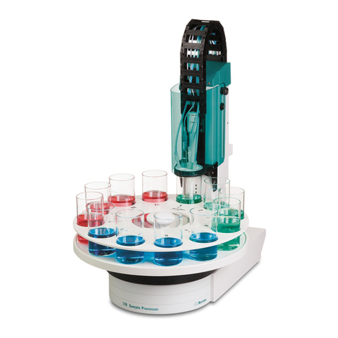
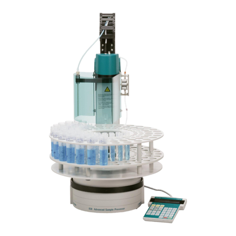
Metrohm 789 User manual

CH-9101 Herisau/Switzerland
E-Mail [email protected]
www.metrohm.com
789 Robotic Sample Processor XL
778 Sample Processor
Program version 5.789.0020+
and 5.778.0020+
Instructions for Use
8.789.1063 03.2007 / dm

II Metrohm Sample Processor
Teachware
Metrohm AG
Oberdorfstr. 68
CH-9100 Herisau
These instructions are protected by copyright. All rights reserved.
Although all the information given in these instructions has been checked with great
care, errors cannot be entirely excluded. Should you notice any mistakes please in-
form the author at the address given above.
© Metrohm AG 2007
Printed in Switzerland

Metrohm Sample Processor III
Table of Contents
1Introduction 1
1.1 Instrument description ....................................................................1
1.1.1 Field of application of the Metrohm Sample Processors........................1
1.1.2 Instrument versions..................................................................................3
1.2 Sample Processors as part of a system ........................................5
1.3 Information about these Instructions for Use................................6
1.3.1 Please note ..............................................................................................6
1.3.2 Additional documents..............................................................................6
1.3.3 Notation and pictograms.........................................................................6
1.4 Parts and controls ...........................................................................7
1.4.1 Overall view..............................................................................................7
1.4.2 Rear view..................................................................................................8
1.5 Connections.....................................................................................9
1.5.1 Sensors of the Sample Processor...........................................................9
1.6 Accessories .................................................................................. 11
1.7 The keypad.................................................................................... 13
1.7.1 The display.............................................................................................14
1.7.2 The keys.................................................................................................15
1.8 Safety information ........................................................................ 23
1.8.1 General: .................................................................................................23
1.8.2 Electrical safety ......................................................................................23
1.8.3 Personal protection................................................................................24
2Installation 25
2.1 Installation flow chart................................................................... 25
2.2 Instrument setup........................................................................... 26
2.2.1 Setup......................................................................................................26
2.2.2 Mains connection...................................................................................26
2.2.3 Connecting the keypad .........................................................................27
2.2.4 Mounting a 786 Swing Head .................................................................27
2.2.5 Mounting the robotic arm ......................................................................28
2.2.6 Connecting pumps ................................................................................29
2.2.7 Connecting dosing devices and stirrers................................................30
2.3 Data transmission connections ................................................... 31
2.3.1 Remote connections..............................................................................31
2.3.2 Serial connections (RS232) ...................................................................37
2.3.3 Connecting a printer ..............................................................................38
2.4 Connecting up accessories ......................................................... 40

IV Metrohm Sample Processor
2.4.1 Connecting rinsing and aspiration equipment......................................40
2.4.2 Attaching the tubing ..............................................................................41
2.4.3 Installing the titration accessories .........................................................42
2.4.4 Assembling pipetting accessories ........................................................44
2.4.5 Installing a double-hollow needle..........................................................45
2.4.6 Spray nozzles ........................................................................................45
2.4.7 Magnetic stirrer......................................................................................46
2.4.8 Mounting the stand support ..................................................................46
2.4.9 Installing the collection trough...............................................................47
2.4.10 Sample racks.........................................................................................47
2.4.11 Mounting the safety shield ....................................................................48
2.5 Start-up.......................................................................................... 49
3Operation 51
3.1 Operating principles..................................................................... 51
3.1.1 Display ...................................................................................................51
3.1.2 Instrument dialog...................................................................................52
3.1.3 Data input ..............................................................................................54
3.1.4 Text input ...............................................................................................55
3.2 Configuration ................................................................................ 57
3.2.1 Miscellaneous........................................................................................57
3.2.2 Tower settings .......................................................................................59
3.2.3 Rack definitions .....................................................................................61
3.2.4 Dosing units...........................................................................................64
3.2.5 RS232 settings.......................................................................................65
3.3 Composition of a method............................................................. 66
3.3.1 Run sequences and method parameters .............................................66
3.3.2 Sample Processor settings ...................................................................68
3.3.3 Stirrer settings........................................................................................69
3.3.4 Dosing device settings ..........................................................................70
3.3.5 Behavior during timeout ........................................................................71
3.3.6 Manual stop settings .............................................................................72
3.4 Commands.................................................................................... 74
3.4.1 Sample Processor commands..............................................................74
3.4.2 Switching components..........................................................................77
3.4.3 Dosing device control............................................................................78
3.4.4 Communication commands..................................................................80
3.4.5 Auxiliary commands ..............................................................................84
3.5 Managing methods....................................................................... 87
3.5.1 User-defined methods...........................................................................87
3.5.2 POWERUP method................................................................................88
3.6 Run control ................................................................................... 89
3.7 Sample racks ................................................................................ 90

Metrohm Sample Processor V
3.7.1 Metrohm standard sample racks ..........................................................90
3.7.2 Magnet codes........................................................................................91
3.7.3 Rack data...............................................................................................92
3.8 Dosing and liquid handling.......................................................... 95
3.8.1 Dosimats and Dosinos ..........................................................................95
3.8.2 Liquid handling functions ................................................................... 100
3.8.3 The DOS command............................................................................ 101
3.8.4 Pictograms.......................................................................................... 101
3.8.5 Liquid handling functions in detail...................................................... 102
3.8.6 Pipetting equipment............................................................................ 105
3.8.7 Pipetting procedure ............................................................................ 105
3.8.8 Preparing the Dosing unit ................................................................... 106
3.8.9 Pipetting .............................................................................................. 106
3.9 The Remote interface ................................................................. 109
3.9.1 Output lines......................................................................................... 109
3.9.2 Input lines............................................................................................ 109
3.9.3 SCN command ................................................................................... 110
3.9.4 CTL command .................................................................................... 110
3.9.5 Manual stop options ........................................................................... 111
3.10 LEARN mode............................................................................... 112
3.10.1 Setting lift and robotic arm positions.................................................. 112
3.10.2 Rack adjustment................................................................................. 113
3.10.3 Parametrizing sequence commands ................................................. 113
3.11 TRACE function .......................................................................... 114
3.12 Disabling keypad functions ....................................................... 114
3.12.1 Disable whole keypad......................................................................... 114
3.12.2 Disable configuration.......................................................................... 115
3.12.3 Disable parameter .............................................................................. 115
3.12.4 Disable method storage functions ..................................................... 115
3.12.5 Disable display.................................................................................... 115
3.13 786 Swing Head settings ........................................................... 116
4Service, maintenance, errors 119
4.1 Service......................................................................................... 119
4.1.1 Running time meter............................................................................. 119
4.2 Care and maintenance ............................................................... 119
4.3 Error messages .......................................................................... 120
5GLP validation – diagnosis 122
5.1 Validation / GLP .......................................................................... 122
5.2 Initializing the working memory ................................................ 123

VI Metrohm Sample Processor
6Annex 125
6.1 Technical data............................................................................. 125
6.1.1 Keypad.................................................................................................125
6.1.2 Interfaces .............................................................................................125
6.1.3 MSB connections ................................................................................125
6.1.4 Pumps and pump connections...........................................................125
6.1.5 Swing Head connection ......................................................................126
6.1.6 Lift ........................................................................................................126
6.1.7 Turntable..............................................................................................126
6.1.8 Stirrer connection (DIN socket) ...........................................................126
6.1.9 Mains connection ................................................................................126
6.1.10 Safety specifications............................................................................126
6.1.11 Electromagnetic compatibility (EMC)..................................................126
6.1.12 Ambient temperature...........................................................................127
6.1.13 Dimensions and materials...................................................................127
6.2 Standard methods ...................................................................... 128
6.2.1 Titrino ...................................................................................................129
6.2.2 PIP ext ..................................................................................................130
6.2.3 KF_ext. .................................................................................................132
6.2.4 pH_cal..................................................................................................134
6.2.5 Std_add ...............................................................................................135
6.3 Standard equipment ................................................................... 137
6.3.1 Metrohm Sample Processor:...............................................................137
6.3.2 Sample racks and sample beakers ....................................................149
6.3.3 786 Swing Head ..................................................................................153
6.3.4 Connection cables...............................................................................157
6.3.5 Optional accessories and additional devices.....................................158
6.3.6 Electrodes for automation ...................................................................161
6.4 Warranty and conformity.......................................................... 1621
6.4.1 Warranty.............................................................................................1621
6.4.2 Declaration of Conformity (778 Sample Processor) .........................1632
6.4.3 Declaration of Conformity (789 Robotic Sample Processor XL) ......1643
6.4.4 Quality Management Principles ........................................................1654
7Index 1665

Metrohm Sample Processor VII
List of Illustrations
Fig. 1 System components........................................................................................................5
Fig. 2 Overall view......................................................................................................................7
Fig. 3 Rear view .........................................................................................................................8
Fig. 4 Connection strip...............................................................................................................9
Fig. 5 Magnet sensor for rack code...........................................................................................9
Fig. 6 Beaker sensor on the tower...........................................................................................10
Fig. 7 Sensor on a robotic arm ................................................................................................10
Fig. 8 Accessories ...................................................................................................................11
Fig. 9 Keypad...........................................................................................................................13
Fig. 10 Safety Shield (example shown: 6.2751.0xx for transfer robotic arm) ...........................24
Fig. 11 Mounting the Swing Head .............................................................................................27
Fig. 12 Robotic arm with limiting screw .....................................................................................28
Fig. 13 Mounting the robotic arm ..............................................................................................29
Fig. 13 MSB connections...........................................................................................................30
Fig. 14 Remote cable.................................................................................................................31
Fig. 15 RS232 connections........................................................................................................37
Fig. 16 Distributor piece.............................................................................................................40
Fig. 17 Attaching the tubing.......................................................................................................41
Fig. 18 Macro titration head.......................................................................................................42
Fig. 19 Micro titration head ........................................................................................................42
Fig. 20 Robotic arm with titration accessories ...........................................................................43
Fig. 22 Transfer robotic arm with pipetting accessories............................................................44
Fig. 23 Transfe r robotic arm with double-hollow needle...........................................................45
Fig. 24 Spray nozzles.................................................................................................................45
Fig. 25 741 Magnetic stirrer .......................................................................................................46
Fig. 24 Stand support ................................................................................................................46
Fig. 25 Collection trough............................................................................................................47
Fig. 26 Attaching a sample rack ................................................................................................47
Fig. 27 Sample rack for XL models............................................................................................48
Fig. 28 Mounting the safety shield.............................................................................................48
Fig. 29 Safety shield for Swing Heads.......................................................................................48
Fig. 30 Dialog arrangement .......................................................................................................53
Fig. 31 Text input .......................................................................................................................56
Fig. 32 800 Dosino with Dosing units ........................................................................................95
Fig. 33 Dosing unit from below..................................................................................................96
Fig. 34 Dosing unit - ports .......................................................................................................100
Fig. 35 Remote interface..........................................................................................................125
Tables
Table 1 Model versions (1 tower) .................................................................................................3
Table 2 Model versions (2 towers)................................................................................................4

VIII Metrohm Sample Processor

1.1 Instrument description
Metrohm Sample Processor,Introduction 1
1 Introduction
This section offers you a first overview of the Metrohm Sample Proces-
sors. All the information applies to both the 789 Robotic Sample Proces-
sor XL and the 778 Sample Processor. You are informed about how you
can use these versatile instruments and are introduced to the most im-
portant parts and controls.
1.1 Instrument description
1.1.1 Field of application of the Metrohm Sample Processors
The Metrohm Sample Processors are very versatile instruments in-
tended exclusively for use in factories and laboratories, where they
cover a wide range of applications. In this way they provide an indis-
pensable service wherever large series of samples have to be proc-
essed, no matter whether in the titration, measurement or liquid
handling sectors.
As a result of the extensive communication possibilities you can work
via the parallel Remote and serial RS232 interface not just with the wide
range of Metrohm titrators, measuring instruments and dosing devices,
but you can also work with any other instruments that have a suitable
communications interface; these can be controlled by or control the
Sample Processor. These abilities mean that they are predestined for all
imaginable automation tasks in a modern laboratory, even within highly
integrated laboratory data systems.
Despite their comprehensive range of commands and the numerous
possible configurations, the Metrohm Sample Processors offer an un-
complicated type of operation that is also suitable for routine work as a
result of the possibility of managing user-defined methods.
The standard methods supplied with the instruments can be used for
routine tasks without any further fuss. After a short familiarization period
the user can alter them to meet any particular requirements and store
them in the instrument. This means that, apart from routine work,
Metrohm Sample Processors can also be used for demanding special
applications.
The run sequences for processing the individual samples are freely de-
finable within wide limits. The same applies to the start sequence and

1.1 Instrument description
2 Metrohm Sample Processor,Introduction
final sequence, which have to be carried out once before the start of a
sample series or once after it has been completed. This offers many
advantages, particularly for titrations. The electrode can be conditioned
before the first titration or subjected to a special rinsing process.
A learn mode is available for creating run sequences and, with its help,
command parameters can be set in manual operation.
Exchangeable standard sample racks are available for many sizes of
beakers and test tubes. Freely selectable "special beaker" positions can
be defined for each rack. These are then used for including rinsing or
conditioning beakers, which can be addressed in any part sequence,
on the rack.
By extending the system with a 786 Swing Head the number of samples
to be processed on a rack can be considerably increased. The robotic
arm of the 786 Swing Head allows any point on a sample rack to be
addressed. This means that the number (max. 999 rack positions) and
arrangement of the samples is virtually unlimited. On request we can
supply customer-specific special racks for individual requirements.
Freely definable position tables can be loaded via the RS232 interface
and suitable PC software for the configuration of special racks.

1.1 Instrument description
Metrohm Sample Processor,Introduction 3
1.1.2 Instrument versions
Variously equipped Metrohm Sample Processors models are available:
• All versions of the 789 Robotic Sample Processor XL are suitable
for sample racks of up to 48 cm diameter.
• All versions of the 778 Sample Processor are suitable for sample
racks of up to 42 cm diameter.
Model 2.789.0010
Model 2.778.0010
1 tower with 1 pump
+ 1 ext. pump connection
+ 1 stirrer connection
+ 1 Swing Head connection
Chassis with 3 MSB sockets
for dosing devices and/or
stirrers
+ Remote connection
(25-pin)
+ RS232 connection (9-pin)
+ keyboard connection
Model 2.789.0020
Model 2.778.0020
1 tower with 2 pumps
+ 1 stirrer connection
+ 1 Swing Head connection
Chassis with 3 MSB sockets
for dosing devices and/or
stirrers
+ Remote connection
(25-pin)
+ RS232 connection (9-pin)
+ keyboard connection
Model 2.789.0030
Model 2.778.0030
1 tower without pumps
+ 2 ext. pump connections
+ 1 stirrer connection
+ 1 Swing Head connection
Chassis with 3 MSB sockets
for dosing devices and/or
stirrers
+ Remote connection
(25-pin)
+ RS232 connection (9-pin)
+ keyboard connection
Table 1 Model versions (1 tower)

1.1 Instrument description
4 Metrohm Sample Processor,Introduction
Model 2.789.0110
Model 2.778.0110
2 towers with 2 pumps
+ 2 ext. pump connections
+ 2 stirrer connections
+ 2 Swing Head connec-
tions
Chassis with 3 MSB sockets
for dosing devices and/or
stirrers
+ Remote connection
(25-pin)
+ RS232 connection (9-pin)
+ keyboard connection
Model 2.789.0120
Model 2.778.0120
2 towers with 4 pumps
+ 2 stirrer connections
+ 2 Swing Head connections
Chassis with 3 MSB sockets
for dosing devices and/or
stirrers
+ Remote connection
(25-pin)
+ RS232 connection (9-pin)
+ keyboard connection
Model 2.789.0130
Model 2.778.0130
2 towers without pumps
+ 4 ext. pump connections
+ 2 stirrer connections
+ 2 Swing Head connec-
tions
Chassis with 3 MSB sockets
for dosing devices and/or
stirrers
+ Remote connection
(25-pin)
+ RS232 connection (9-pin)
+ keyboard connection
Table 2 Model versions (2 towers)

1.2 Sample Processors as part of a system
Metrohm Sample Processor,Introduction 5
1.2 Sample Processors as part of a system
772 Pump
685 Dosimat
COM 2
TiNet
2.x
PC
COM 2
LPT 1
PC
COM 1
COMx
USB
RS 232
Remote MSB
711 Liquino
731
Relay Box
DC
AC
MSB
756 KF
RS 232
805 Dosimat805 Dosimat
800
Dosino
800
Dosino
800
Dosino
800
Dosino
700
Dosino
700
Dosino
700
Dosino
700
Dosino
809 Titrando809 Titrando808 Titrando808 Titrando
823823
781pH/Ion Meter Metrohm781pH/Ion Meter Metrohm
Fig. 1 System components
741 Magnetic
Stirrer
772 Pump Unit
Titrinos
pH Meter / Ion Meter
756/831
Coulometer
731 Relay Box
711 Liquino
Titrandos
(6.2148.010 Remote Box
required)
Keypad
Printer
Personal
Computer
802 Rod Stirrer
823 Membrane
Pump Unit
801 Stirrer
804 Titation Stand 800 Dosino
805 Dosimat
700 Dosino
685 Dosimat
• Titrinos
• pH Meter
• Coulometer
• other
Metrohm in-
struments
• other manu-
facturers in-
struments
• Titrinos
• pH Meter
• Coulometer
• other Metrohm instruments
• balance
• instruments from
other manufacturers
• other Metrohm
instruments
786 Swing Head* 786 Swing Head**
786 Swing Head
* with titration-robotic arm
** with transfer-robotic arm

1.3 Information about these Instructions for Use
6 Metrohm Sample Processor,Introduction
1.3 Information about these Instructions for Use
1.3.1 Please note
Please read through these Instructions for Use carefully before you
start to use the Sample Processor. The instructions contain information
and warnings that must be observed by the user in order to guarantee
the safe use of the instrument.
1.3.2 Additional documents
• Quick Reference 8.789.1013 for the Metrohm Sample Processors
• Operating Tutorial 8.789.1023 for the Metrohm Sample Processors
• Technical Reference 8.789.1033 for the Metrohm Sample Proces-
sors
1.3.3 Notation and pictograms
The following notation and pictograms are used in these Instructions for
Use:
Location Menu item, parameter or input value
<OK> button, key
Danger
This symbol indicates a possible risk of death or injury to
the user if the instructions are not followed correctly.
Warning
This symbol indicates a possible risk of damage to the in-
struments or their components if the instructions are not fol-
lowed correctly.
Attention
This symbol indicates important information. Read the in-
formation provided before you continue.
Remarks
This symbol indicates additional information and tips.

1.4 Parts and controls
Metrohm Sample Processor,Introduction 7
1.4 Parts and controls
1.4.1 Overall view
Fig. 2 Overall view
1 Guide chain 6 Splash protection guide
2 Safety shield/Splash protection 7 Titration head
3 Sample rack 8 Lift
4 Stirrer rail 9 Tower
5 Splash protection fixing 10
Beaker sensor
11
Chassis
1
2
3
4
5
6
7
8
9
10
11
Safety information
Safety shield 2must always be in po-
sition before the Metrohm Sample
Processor is used.

1.4 Parts and controls
8 Metrohm Sample Processor,Introduction
1.4.2 Rear view
This illustration shows the rear view of the standard model 2.778.0010 with
one tower, one membrane pump and one connection for an external pump.
WARNING-FireHazard-
withthesametypeandratingoffuse
Forcontinuedprotectionreplaceonly
Made by Metrohm
Herisau Switzerland
S: 115 VA U : 100 - 240 V f: 50 - 6 0 H z
RS 232
MSB1
MSB3
MSB2
Power Keyboard
Remote
Ext.
Pump 2
Swing
Head
Pump 1
Fig. 3 Rear view
12 Distributor block 16 Stirrer connection (Tower 1)
For 802 Rod Stirrer or
741 Magnetic Stirrer
13 Membrane pump 17
Connection strip
14 PTFE tubing 18
Pump connection M8 (external)
15 Solenoid valve 19
Connection socket for the
786 Swing Head
a Warning: Biohazard
See Section 1.8.3 Personal protection
b
Warning: Resistance to chemicals
See section 2.4.1 Connecting rinsing
and aspiration equipment
12
13
14
15
16
17
18
19

1.5 Connections
Metrohm Sample Processor,Introduction 9
1.5 Connections
The electrical connections are the same for all models of the Metrohm
778/789 Sample Processor series.
WARNING-FireHazard-
withthesametypeandratingoffuse
Forcontinuedprotectionreplaceonly
Made by Metrohm
Herisau Switzerland
S: 115 VA U: 100 - 240 V f: 50 - 60 H z
RS 232
MSB1
MSB3
MSB2
Power Keyboard
Remote
Fig. 4 Connection strip
20 Mains switch 24 Serial RS232 connection (9-pin)
21 Keyboard connection 25
Mains connection
22 MSB connections MSB1 … MSB3
Metrohm Serial Bus
Connection of dosing devices and stir-
rers
26
Type plate
23 Remote connection (25-pin)
1.5.1 Sensors of the Sample Processor
Fig. 5 Magnet sensor for rack code
Rack sensor
The magnet sensor for recognizing
the individual rack code is located be-
neath the turntable of the Sample
Processor. The magnet code of a
rack can only be read in when the
rack is in the initial position. The mag-
net holder must be positioned directly
above the sensor.
For this reason the Sample Processor
should be initialized each time that a
rack is changed with the <RACK>
key.
20
21 22
23 24
25 26
Magnet
sensor
Magnet holder

1.5 Connections
10 Metrohm Sample Processor,Introduction
Fig. 6 Beaker sensor on the
tower
Optical beaker sensor
Each tower of a Metrohm Sample
Processor is equipped with a beaker
sensor that detects the presence of
a beaker in front of the tower. With
this infrared sensor beakers made
from different materials can be de-
tected, provided that they are lo-
cated in the correct position in front
of the tower and the beaker sensor
'Tower' has been selected in the
rack definition. This "Beaker test" is
carried out after each MOVE com-
mand (i.e. each rotation of the rack).
The beaker sensor on the tower can
only be used with single-row sample
racks.
Fig. 7 Sensor on a robotic arm
Tactile robotic arm sensor
Robotic arms with piezo sensors
may be used with multi-row racks.
The sensor is activated, when the lift
is run to work position and makes
physical contact with a sample
beaker.
Splash protection
/
Safety shield
Beaker sensor
Sample rac
k
Piezo sensor

1.6 Accessories
Metrohm Sample Processor,Introduction 11
1.6 Accessories
Fig. 8 Accessories
With suitable accessories a Sample Processor can be extended to form
a comprehensive automated system. Depending on the tasks to be
carried out, various standard components or even custom-made spe-
cial parts can be used. Please consult the list of accessories on page
137ff.
Sample racks
Custom-made racks for various vessel sizes with any arrangement of
rack positions can also be supplied in addition to the standard racks.
786 Swing Head with robotic arm
The use of multi-row sample racks or external titration cells requires the
use of a 786 Swing Head. This motor drive, which is mounted on the lift
of one of the Sample Processor towers, can move different types of ro-
botic arm. Various types of standard robotic arms with accessories for
titrating on the sample rack or for sample transfer to an external titration
cell are available.
Stand support
If an external titration cell is to be used then we recommend the use of
a stand support. The stand support can accommodate a magnetic stir-
rer (e.g. model 801) and, with a support rod, enables you to attach a ti-
tration cell or other accessories.
786 Swing Heads
Stand su
pp
ort
Robotic arm with
titration head
Sample rac
k
Robotic arm for
sample transfer

1.6 Accessories
12 Metrohm Sample Processor,Introduction
Swing head with tactile piezo sensor
When using a multi-row rack and a 786 Swing Head, a robotic arm with
a touch-sensitive piezo sensor may be used. With that kind of sensor
the presence of a sample beaker can be detected reliably.
Robotic arm for removing covers
Whenever covered sample containers are required (e. g. with volatile
samples) the lids can be removed by a special robotic arm (so called
Dis-Cover) with magnetic contact before the sample treatment. Special
lids are available for this purpose.
Accessory set for sample transfer
For pipetting samples into external titration cells an accessory set
(6.5619.000) is available, comprising all necessary parts.
Other manuals for 789
1
This manual suits for next models
1
Table of contents
Other Metrohm Computer Hardware manuals
Popular Computer Hardware manuals by other brands
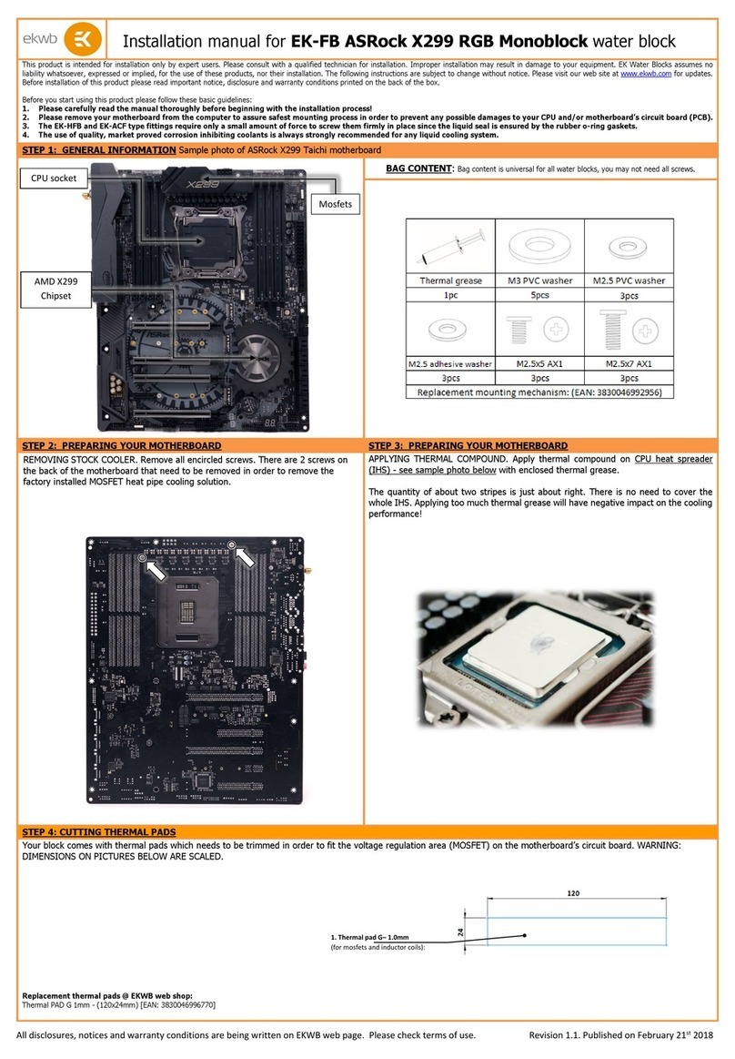
ekwb
ekwb EK-FB ASRock X299 RGB Monoblock installation manual
Quanmax
Quanmax QBOX-2090 Series user guide

Runco
Runco DHD Series Owner's operating manual
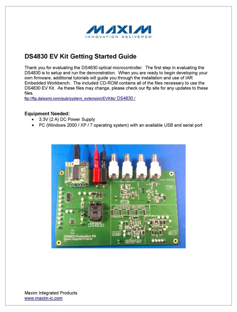
Maxim
Maxim DS4830 Getting started guide
National Semiconductor
National Semiconductor COP400-E02 user manual
Siemens
Siemens SIMATIC NET CP 243-1 Technical manual
