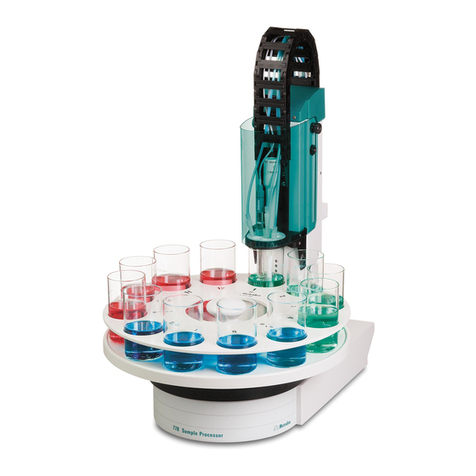
Metrohm 838 Advanced Sample Processor User manual

CH-9101 Herisau/Switzerland
www.metrohm.com
838 Advanced Sample Processor
Program version 5.838.0012
Installation Instructions
8.838.1313 09.2005 / dm

II 838 Advanced Sample Processor
Teachware
Metrohm AG
Oberdorfstr. 68
CH-9100 Herisau
These instructions are protected by copyright. All rights reserved.
Although all the information given in these instructions has been checked with great
care, errors cannot be entirely excluded. Should you notice any mistakes please in-
form the author at the address given above.
© Metrohm AG 2005
Printed in Switzerland

838 Advanced Sample Processor III
Table of contents
1Introduction 1
1.1 Instrument description ......................................................................1
1.1.1 Scope of application of the 838 Advanced Sample Processor ................1
1.1.2 Instrument models and available versions................................................2
1.2 Information about this Installation Instructions ..............................4
1.2.1 Note............................................................................................................4
1.2.2 Notation and pictograms ...........................................................................4
1.3 Parts and controls .............................................................................5
1.3.1 Overall view ................................................................................................5
1.3.2 Rear panel..................................................................................................6
1.3.3 Connections ...............................................................................................7
1.3.4 Injection valve.............................................................................................7
1.3.5 Peristaltic pump .........................................................................................8
1.3.6 Sensors of the Advanced Sample Processor............................................8
2Safety notes 9
2.1 General...............................................................................................9
2.2 Electrical safety .................................................................................9
2.3 Personal protection ........................................................................ 10
3Installation 11
3.1 Installation flowchart...................................................................... 11
3.2 Instrument setup............................................................................. 13
3.2.1 Setup ........................................................................................................13
3.2.2 Mains connection.....................................................................................13
3.3 Fitting the accessories................................................................... 14
3.3.1 Connecting the keypad............................................................................14
3.3.2 Connecting the Swing Head....................................................................14
3.3.3 Fitting the retention plate .........................................................................15
3.3.4 Fitting the needle or tubing ......................................................................15
3.3.5 Fitting the filtration cell holder or Dosino holder......................................16
3.3.6 Fitting the ultrafiltration cell ......................................................................17
3.3.7 Fitting the dialysis cell..............................................................................20
3.3.8 Fitting the Dosino .....................................................................................22
3.3.9 Tubing connections .................................................................................23
3.3.10 Pump tubings...........................................................................................25
3.3.11 Connection of the ultrafiltration cell .........................................................27
3.3.12 Connecting the dialysis cell .....................................................................29
3.3.13 Inserting capillaries or tubings.................................................................34
3.3.14 Fitting the stand bracket ..........................................................................34

IV 838 Advanced Sample Processor
3.3.15 Connecting pumps ..................................................................................35
3.3.16 Connector dosing drives and stirrers ......................................................35
3.3.17 Installing the catch pan ...........................................................................36
3.3.18 Sample racks ...........................................................................................36
3.3.19 Fitting the safety guard/splash guard .....................................................37
3.4 Connecting external instruments .................................................. 38
3.4.1 General information on interface connections ........................................38
3.4.2 Serial connections (RS232) .....................................................................39
3.4.3 Remote interface......................................................................................39
3.5 Connection to Metrohm IC systems.............................................. 40
3.5.1 IC system remotely controlled by PC ......................................................40
3.5.2 Metrohm IC systems................................................................................40
3.5.3 MIC-2 modular anionic system with chemical suppression ...................41
3.5.4 MIC-2 modular anionic system with chemical suppression and sample
dilution ..................................................................................................42
3.5.5 Capillary connections for sample dilutions .............................................44
3.5.6 Equipping the work head of the mixing container ..................................45
3.5.7 MIC-2 modular anionic system with chemical suppression and
ultrafiltration of the samples .................................................................46
3.5.8 MIC-3 modular anionic and cationic system with chemical suppression47
3.5.9 MIC-7 anionic system with chemical suppression and dialysis .............48
3.5.10 MIC-8 modular system with 817 Bioscan for the sugar analysis............52
3.5.11 Connection to 761 Compact IC or 790 Personal IC................................53
3.6 Connection to Metrohm VA systems............................................. 56
3.6.1 Connection to a Metrohm 797 VA Computrace......................................56
3.6.2 MVA-13 modular system for automatic analysis of electroplating baths57
3.6.3 Accessories for sample volumes greater than 10 ml..............................57
3.7 Sample racks .................................................................................. 59
3.7.1 Metrohm standard sample racks ............................................................59
3.7.2 Magnetic codes .......................................................................................60
4Service, maintenance, faults 61
4.1 Servicing ......................................................................................... 61
4.2 Care and maintenance ................................................................... 61
4.2.1 Exchanging pump tubings ......................................................................61
4.2.2 Replacing the filtration membrane ..........................................................63
4.2.3 Replacing the dialysis membrane ...........................................................65
5GLP validation – diagnosis 66
5.1 Validation / GLP .............................................................................. 66
6Annex 67
6.1 Filtration .......................................................................................... 67
6.1.1 Selection of possible sample types.........................................................67

838 Advanced Sample Processor V
6.1.2 Filter working life ......................................................................................68
6.1.3 Filter membrane selection .......................................................................68
6.2 Technical data ................................................................................ 70
6.2.1 2 Channel peristaltic pump......................................................................70
6.2.2 Pump connections...................................................................................70
6.2.3 Injection valve...........................................................................................70
6.2.4 Keypad with LCD display.........................................................................70
6.2.5 Interfaces..................................................................................................71
6.2.6 MSB connections.....................................................................................71
6.2.7 Swing Head connection...........................................................................71
6.2.8 Lift.............................................................................................................71
6.2.9 Turntable ..................................................................................................71
6.2.10 Stirrer connection (DIN socket)................................................................71
6.2.11 Mains connection.....................................................................................71
6.2.12 Safety specification ..................................................................................72
6.2.13 Electromagnetic compatibility (EMC) ......................................................72
6.2.14 Ambient temperature ...............................................................................72
6.2.15 Dimensions and material .........................................................................73
6.3 Standard equipment....................................................................... 74
6.3.1 Metrohm 838 Advanced Sample Processor ...........................................74
6.3.2 Keyboard (optional) .................................................................................91
6.3.3 Dosing drive and units .............................................................................91
6.3.4 Rührer.......................................................................................................91
6.3.5 Sample racks and vessels.......................................................................92
6.3.6 786 Swing Head.......................................................................................93
6.3.7 Connecting cables...................................................................................95
6.3.8 Filtration and dialysis accessories...........................................................95
6.3.9 Pump tubing.............................................................................................96
6.3.10 Needles and tubings................................................................................97
6.4 Warranty.......................................................................................... 98
6.5 Declaration of Conformity.............................................................. 99
6.5.1 Quality Management Principles............................................................ 100
7Index 101
Tables
Table 1 Instrument models............................................................................................................2
Table 2 Available versions.............................................................................................................3
Table 3 Pump tubings .................................................................................................................26
Table 4 MIC systems...................................................................................................................40
Table 5 Sample racks..................................................................................................................59
Table 6 Filtering various samples................................................................................................67
Table 7 Selection of the filtration membrane...............................................................................69

VI 838 Advanced Sample Processor
List of illustrations
Figure 1 Models 2.838.0x10 without injection valve .....................................................................2
Figure 2 Models 2.838.0x20 with injection valve........................................................................... 2
Figure 3 Overall view..................................................................................................................... 5
Figure 4 Rear panel....................................................................................................................... 6
Figure 5 Connection panel............................................................................................................ 7
Figure 6 Injection valve ................................................................................................................. 7
Figure 7 Peristaltic pump with 2 tubing cartridges ....................................................................... 8
Figure 8 Magnet sensor for rack code.......................................................................................... 8
Figure 9 Safety Guard (example shown. 6.2751.0xx for transfer robotic arm) .......................... 10
Figure 10 Mains connection socket............................................................................................ 13
Figure 11 Connecting the keypad............................................................................................... 14
Figure 12 Connecting the Swing Head....................................................................................... 14
Figure 13 Fitting the retention plate ............................................................................................ 15
Figure 14 Fitting the needle ........................................................................................................ 15
Figure 15 Filtration cell holder..................................................................................................... 16
Figure 16 Dosino holder ............................................................................................................. 16
Figure 17 Fitting the ultrafiltration cell ......................................................................................... 17
Figure 18 Fitting the dialysis cell................................................................................................. 20
Figure 19 Fitting the dialysis cell into the 6.2057.010 holder...................................................... 21
Figure 20 Fitting the Dosino........................................................................................................ 22
Figure 21 Threaded adapter GL 45 (6.1618.020) ....................................................................... 22
Figure 22 Fitting pump tubing..................................................................................................... 23
Figure 23 Connecting the ultrafiltration cell ............................................................................... 27
Figure 24 Capillary connections for dialysis ............................................................................... 29
Figure 25 Inserting capilliaries or tubings ................................................................................... 34
Figure 26 Stand bracket.............................................................................................................. 34
Figure 27 MSB connections........................................................................................................ 35
Figure 28 Catch pan ................................................................................................................... 36
Figure 29 Fitting the sample rack ............................................................................................... 36
Figure 30 Fitting the safety guard ............................................................................................... 37
Figure 31 MIC-2 interconnection with anionic system with chemical suppression .................... 41
Figure 32 MIC-2 interconnection with anionic system with chemical suppression and sample
dilution....................................................................................................................... 42
Figure 33 Capilliary connections for sample dilutions ................................................................ 44
Figure 34 Equipping the mixing container .................................................................................. 45
Figure 35 MIC-2 interconnection with anionic system with chemical suppression .................... 46
Figure 36 MIC-3 interconnection with modular anionic and cationic system with chemical
suppression .............................................................................................................. 47
Figure 37 MIC-7 interconnection with anionic system with chemical suppression and dialysis 48
Figure 38 MIC-8 interconnection with modular system with 817 Bioscan for sugar analysis..... 52
Figure 39 Interconnection with the 761 Compact IC via PC (RS232 only) .................................53
Figure 40 Interconnection with compact systems via remote connection (PC-controlled) ........ 54
Figure 41 Interconnection with 797 VA Computrace .................................................................. 56
Figure 42 MVA-13 connection to an analysis system for electroplating baths...........................57
Figure 43 Accessories for larger sample volumes...................................................................... 57
Figure 44 Remote interface......................................................................................................... 71

1.1 Instrument description
838 Advanced Sample Processor, Introduction 1
1 Introduction
This Chapter offers you an initial overview of the Metrohm 838 Advanced
Sample Processor and its instrument versions. It tells you how you can
use this versatile instrument and familiarises you with the most important
operating controls.
1.1 Instrument description
1.1.1 Scope of application of the 838 Advanced Sample Processor
The Metrohm 838 Advanced Sample Processor is an instrument with
diverse applications and is designed specifically for sample preparation
in ion chromatography. Thanks to its flexibility however, it can also be
used for other tasks. Online filtration, dialysis, preparation of dilutions,
sample enrichment, inline calibration and partial loopfill etc. are tech-
niques which can be used easily with the 838 Advanced Sample Proc-
essor. The entire range of tasks in sample preparation can be
automated to save time.
Thanks to the very extensive communication options, the Sample Proc-
essor operates not only together with the broad range of Metrohm in-
struments via the parallel remote interface and serial RS232 interface.
Any instruments featuring a suitable communication interface can be
coordinated with this instrument.
Interchangeable standard sample racks are available for many vessel
sizes. Freely selectable "special beaker" positions can be used on each
rack.
Equipping with a 786 Swing Head with robotic arm allows any point on
a sample rack to be approached. This means that the number of sam-
ples (max. 999 rack positions) and arrangement of the samples on the
sample rack can be selected virtually at will. Special customer-specific
racks for individual needs can be manufactured on request.

2838 Advanced Sample Processor, Introduction
1.1.2 Instrument models and available versions
There are various models and available versions of the Metrohm 838
Advanced Sample Processor with various accessories.
Instrument models
• 838 Advanced Sample Processor with Swing Head, peristaltic
pump and 2 pump connections
• 838 Advanced Sample Processor with Swing Head, peristaltic
pump, injection valve, and 2 pump connections
Figure 1 Models 2.838.0x10
without injection valve
Figure 2 Models 2.838.0x20
with injection valve
Tower with 786 Swing Head
+ peristaltic pump
+ 2 external pump connections
+ 1 stirrer connection
Chassis with 3 MSB sockets for dosing drive
and/or stirrer
+ remote socket (25-pin)
+ RS232 connection (9-pin)
+ keypad connection
Tower with 786 Swing Head
+ peristaltic pump
+ injection valve
+ 2 external pump connections
+ 1 stirrer connection
Chassis with 3 MSB sockets for dosing drive
and/or stirrer
+ remote socket (25-pin)
+ RS232 connection (9-pin)
+ keypad connection
Table 1 Instrument models

1.1 Instrument description
838 Advanced Sample Processor, Introduction 3
Available versions
2.838.0010 Advanced IC Sample Processor
Model without injection valve, without keypad, with
standard accessories
2.838.0020 Advanced IC Injection Sample Processor
Model with injection valve, without keypad, with
standard accessories
2.838.0110 Advanced IC Dialysis Sample Processor
Model without injection valve, without keypad, with
dialysis accessories
2.838.0120 Advanced IC Dilution Sample Processor
Model with injection valve, without keypad, with ac-
cessories for sample dilution
2.838.0210 Advanced IC Ultrafiltration Sample Processor
Model without injection valve, without keypad, with
filtration accessories
2.838.0310 Advanced VA Sample Processor
Model without injection valve, with keypad, with VA
accessories
Table 2 Available versions
The 2.838.00xx and 2.838.02xx versions (no keypad) are intended as
ion chromatography systems, controlled by «IC Net».
The 2.838.0310 version (with keypad) is the stand-alone system version
for voltammetric applications. Sample treatment is controlled by instru-
ment methods of the Sample Processor.
«IC Net 2.3» (Service release 3 or later) sets a parameter in the 838
Advanced Sample Processor, which forces the Sample Processor to
reset all of it's device settings and delete all stored methods on start-
up (RAM init). This behavior is intended and required for controlling the
Sample processor with «IC Net».
If a 838 Advanced Sample Processor is to be used as a stand-alone
system with keypad control and instrument methods, which previously
was controlled by «IC Net 2.3», the setting mentioned above has to be
switched off beforehand. In «IC Net» uncheck the check box "Autoinit"
which is accessible after right-clicking the Sample Processor icon in
the working system.

4838 Advanced Sample Processor, Introduction
1.2 Information about this Installation Instructions
1.2.1 Note
Attention!
Please study these Installation Instructions carefully before you start to
use the Instrument. The instructions contain information and warnings
that must be observed by the user in order to guarantee the safe use
of the instrument. Please keep these instructions near the instrument
so that they are always to hand when required.
1.2.2 Notation and pictograms
The following notation and pictograms are used in these Instructions:
9 Control element, instrument element
<OK> Button, Key
Danger/Warning
This symbol indicates a possible risk of death or injury to
the user and possible damage to the instrument or its
components by electricity.
Danger/Warning
This symbol indicates a possible risk of death or injury to
the user and possible damage to the instrument or its
components.
Attention
This symbol indicates important information that you should
read before continuing.
Information
This symbol indicates additional information and tips which
may be of particular use to you.

1.3 Parts and controls
838 Advanced Sample Processor, Introduction 5
1.3 Parts and controls
1.3.1 Overall view
Figure 3 Overall view
1 Guide chain 6 Swing Head
2 Safety guard/splash protection 7 Injection valve *
3 Sample rack 8 Robotic arm** with needle adapter
4 Stirrer rail 9 Retention plate *
5 Peristaltic pump 10
Holder for ultrafiltration cell ***
11
Chassis
* optional, depending on available version
** robotic arm model 6.1462.030
***depending on available version, holder for ultrafiltration cell/dialysis cell or Dosino holder
1
2
3
4
5
6
7
8
9
10
11
Safety note
The safety guard 2must always be fitted
before operating an 838 Advanced Sample
Processor.

6838 Advanced Sample Processor, Introduction
1.3.2 Rear panel
Swing
Head
Ext.
Pump 2
Ext.
Pump 1
WARNING-FireHazard-
withthesamet ypeandratingoffuse
Forcontinuedprotectionrepla ceonly
Made by Metrohm
Herisau Switzerland
S: 115 VA U: 100 - 240 V f: 50 - 60 Hz
RS 232
MSB1
MSB3
MSB2Pow er Keyboard
Remote
1
.8
38
.0
0
1
0
0
1
1
07
Figure 4 Rear panel
12 Pump connections M8 (external)
for 772 or 823 pump models
15 Connection panel
13 Stirrer connection
for 802 rod stirrer or
741 magnetic stirrer
a
Warning:
Biohazard
See Chapter 2.3 Personal protection
14 Connection socket for the
786 Swing Head
12
13 14
15
a

1.3 Parts and controls
838 Advanced Sample Processor, Introduction 7
1.3.3 Connections
WARNING-FireHazard-
withthesametypeandratingoffuse
Forcontinuedprotectionreplaceonly
Made b y M etrohm
Herisau Switzerland
S: 11 5 VA U : 100 - 240 V f: 50 - 60 Hz
RS 232
MSB1
MSB3
MSB2
Power Keyboard
Remote
Figure 5 Connection panel
16 Power switch 20 Serial RS232 connection (9-pin)
17 Keypad connection 21 Mains connection
18 MSB connections MSB1 … MSB3
Metrohm Serial Bus
Connection of dosing drives and stir-
rers
22 Instrument number
19 Remote connection (25-pin)
1.3.4 Injection valve
54
12
63
The injection valve on the right-hand side of the tower, with its connec-
tions 1 to 6 (see Figure at left), can be used for complex sample prepa-
ration steps. The schematic below shows the assignments of the
connections in the switch positions FILL and INJECT.
Figure 6 Injection
valve
Fill
Inject
If not in use, the injection valve should be protected against dust con-
tamination with the red protective cap.
16 17 18 19 20 21 22

8838 Advanced Sample Processor, Introduction
1.3.5 Peristaltic pump
The peristaltic pump of the 838 Advanced Sample Processor can be
used as a single-channel or two-channel pump. One or two tubing car-
tridges 6.2755.000 may be fitted.
Figure 7 Peristaltic pump with 2 tubing cartridges
48 Tubing cartridge (6.2755.000)
For pump tubing (6.1826.0X0)
51 Snap-action lever
For detaching the tubing cartridge
49 Pressure lever
For regulating the contact pres-
sure
52 Pump drive
Roller head with contact rollers
50 Retaining bracket 53 Retaining cam
For engaging the tubing car-
tridges
1.3.6 Sensors of the Advanced Sample Processor
Figure 8 Magnet sensor for rack code
The magnet sensor for detecting the individ-
ual rack codes is mounted beneath the turn-
table of the Advanced Sample Processor.
The magnetic code of a rack can be read
only if the rack is in initial position, i.e. if the
magnet holder is precisely above the sensor.
For this reason, the Sample Processor
should be switched off and back on again
with each rack change.
Magnet sensor
Magnet holder
48
49
51
53
52
50

2.1 General
838 Advanced Sample Processor, Safety notes 9
2 Safety notes
Warning!
This instrument should only be used in accordance with the information
given in these installation instructions.
2.1 General
This instrument left our works in perfect condition from the point of view
of its operational safety (see Technical data, safety specifications). To
keep it in this condition and to continue to operate safely the following
information must be carefully observed.
2.2 Electrical safety
Please observe the following guidelines:
• Only qualified Metrohm personnel should carry out service work on
electronic components.
• Do not open the instrument housing as this could damage the in-
strument. The housing contains no components which could be
serviced or exchanged by the user.
Electrical safety when handling the instrument is guaranteed within the
scope of Standard IEC 61010-1.
• Protection against electrostatic charges
Warning!
Electronic components are sensitive to electrostatic charges and can
be destroyed by a discharge. Before you touch any electronic compo-
nents of the Sample Processor you should ground you and your tools
by grasping a grounded object (e.g. the instrument housing or a radia-
tor) in order to eliminate any electrostatic charges that may be present.
• Opening a Sample Processor
When the Sample Processor is connected to the mains supply the in-
strument must not be opened, nor should any of its components be
dismantled as otherwise you could come into contact with current-
carrying components. Before opening the instrument separate it from all
current sources and make sure that mains cable has been removed
from the mains connection socket!

10 838 Advanced Sample Processor, Safety notes
• Mains connection
This instrument must only be operated at the specified mains voltages
(see rear panel of instrument).
2.3 Personal protection
The different drives of the Advanced Sample Processor and the Swing
Head possess considerable force in order that they can freely move
even under heavy loads. They are fitted with electronic overload limiters
that are triggered if the mechanical resistance is too high.
When the instrument is running do not intrude in the working range
of the Sample Processor.
For the user there is a considerable risk of injury from manual inter-
ference with the automatic processes of the instrument.
Important!
Before you use the instrument for the first time you must install the in-
cluded 6.2751.0xx Safety Guard, see p. 37.
The Sample Processor must not be operated without the Safety Guard
in position!
Figure 9 Safety Guard
(example shown. 6.2751.0xx for transfer robotic arm)
Biohazard
The Advanced Sample Processor does not provide sufficient protection
when processing potentially infectious samples or reagents.
In this case install the necessary safety devices.

3.1 Installation flowchart
838 Advanced Sample Processor, Installation 11
3 Installation
This Chapter describes installation of all components of a Metrohm
Sample Processor and illustrates how to connect it to other instruments.
Please read the following sections carefully and follow the instructions in
detail. This is the only way of ensuring that a Sample Processor will func-
tion correctly.
3.1 Installation flowchart
The following installation flowchart provides an overview of the required
installation work. Please refer to the specified Chapters for further in-
formation.
Installation Chapter 3.2
Ø
Connecting the keypad Chapter 3.3.1
Ø
Connecting the mains cable Chapter 3.2.2
Ø
Connecting the Swing Head Chapter 3.3.2
Ø
* Fitting the retention plate Chapter 3.3.3
Ø
Fitting the needle or tubing Chapter 3.3.4
Ø
* Fitting the filtration cell holder or Dosino holder
Chapter 3.3.5
Ø
* Fitting the ultrafiltration cell Chapter 3.3.6
Ø
* Fitting the dialysis cell Chapter 3.3.7
Ø

12 838 Advanced Sample Processor, Installation
Tubing connections Chapter 3.3.8
Ø
* Fitting the stand bracket Chapter 3.3.14
Ø
* Connecting the pumps Chapter 3.3.15
Ø
* Connecting the dosing drive and stirrer Chapter
3.3.16
Ø
* Installing the catch pan Chapter 3.3.17
Ø
Sample racks Chapter 3.3.18
Ø
Fitting the safety guard Chapter 3.3.19
* optional

3.2 Instrument setup
838 Advanced Sample Processor, Installation 13
3.2 Instrument setup
3.2.1 Setup
Packaging
An 838 Metrohm Advanced Sample Processor and its specially packed
accessories are supplied in very protective special packaging consist-
ing of shock-absorbing plastic foam. Please store this packaging in a
safe place; it is the only way in which the safe transport of the instru-
ment can be guaranteed.
Checks
Please check that the delivery is complete and undamaged immedi-
ately on receipt (compare with delivery note and list of accessories
given in Section 6.3 ). If transport damage is evident please refer to the
information given in Section 6.4 "Warranty".
Location
The 838 Advanced Sample Processor is a robust instrument and can
therefore be used even in rough surroundings in laboratories and facto-
ries.
However, please ensure that it is not exposed to a corrosive atmos-
phere. The instrument should be serviced at regular intervals, particu-
larly when operated under rough conditions.
3.2.2 Mains connection
This instrument must only be operated at the specified mains voltages
(see rear panel of instrument).
Protect the connection sockets against moisture.
S: 115 VA U: 100 - 240 V f: 50 - 60 Hz
Figure 10 Mains connection socket
Mains connection 21

14 838 Advanced Sample Processor, Installation
3.3 Fitting the accessories
3.3.1 Connecting the keypad
Figure 11
Connecting the
keypad
(Only required if Sample Processor methods are to
be used and edited).
The 6.2142.050 keypad must be connected to the
instrument rear panel at the keypad socket 17 pro-
vided. The instrument must be switched off before
doing this. Squeeze the connector together at both
sides in order to disconnect the connector.
After connecting the keypad, you can switch on
the 838 Advanced Sample Processor at the power
switch 16. The display on the keypad starts to
light. The instrument is initialised and the lift is
raised fully.
3.3.2 Connecting the Swing Head
Swing
Head
Figure 12
Connecting the
Swing Head
Connect to the Swing Head connection socket 14
Route the connection cable of the Swing Head through the guide chain
of the tower and connect the Mini-DIN connector of the Swing Head
connection cable to the Swing Head socket on the rear panel of the
tower.
If a robotic arm other than the Type 6.1462.030 supplied as standard is
to be used, it will be necessary to make configuration settings. You will
require a 6.2142.050 keypad to do this.
Configuring the Swing Head and robotic arm
Since each type of robotic arm has different geometrical dimensions, it
is absolutely essential to adapt the Setup settings for the Swing Head
to the relevant type of robotic arm. No settings need to be made for the
robotic arm supplied as standard.
Changes are made in the Setup dialog box. The individual settings re-
late to:
• swing offset
• maximum swing angle
• swing radius
• swing direction
You can open the Sample Processor's Setup dialog by pressing the
<CONFIG> key on the keypad during switch-on of the instrument.
Other manuals for 838 Advanced Sample Processor
2
Table of contents
Other Metrohm Computer Hardware manuals
Popular Computer Hardware manuals by other brands

Renesas
Renesas RA4T1 quick start guide

Kurzweil
Kurzweil PCR-1 installation instructions

Microchip Technology
Microchip Technology DS61160A user guide
Shenzhen Gongjin Electronics
Shenzhen Gongjin Electronics WNA699U8G.1 user manual

TC Electronic
TC Electronic Finalizer Express Specifications
Allied Telesis
Allied Telesis AT-SPZX80 specification
Yamaha
Yamaha DB-SREV1 owner's manual
Sony
Sony SVT-RS1A operating instructions
HighPoint
HighPoint U.2 Series Quick installation guide
Delta Electronics
Delta Electronics SMT Power Inductor SI54 Specifications

ekwb
ekwb EK-FB ASUS Maximus XI HERO installation manual
Supermicro
Supermicro BPN-SAS3-LB16A-N10 user guide
