Meusburger E 6350 Force User manual

Pmax
N2
Pmax
bar / psi
Pmax =
max. Druck
maximum pressure
bar / psi
1
H
7
49
2
3
6
M
8
11
10
N2
N2
N2
100% Hub/stroke
<100% Hub/stroke
min 75 %
L - Hub/stroke
Körper Ø + 1
body Ø + 0.5
L
B
DEF
C
> 0
Ok all Cu
Hub
stroke
Körper Ø + 6
body Ø + 5
L
B
DEF
C
> 0
Ok all Cu
Hub
stroke
B
DEF
C
> 0
Ok all Cu
Körper Ø + 3.3
body Ø + 3
Körper Ø + 4.3
body Ø + 4
L
Hub
stroke
≤ 63
75
min 75% di L
Body Ø + 0,5 + 1,0
L
B
DEF
C
> 0
Cu 38
alle Hübe
all strokes
±90º
90º
A
U
G
E
N
S
C
H
U
T
Z
E
Y
E
P
R
O
T
E
C
T
I
O
N
AB
A
D
alle Hübe
all strokes
min 75% di L
Body Ø + 0,5 + 1,0
L
B
DEF
C
> 0
Cu 38
alle Hübe
all strokes
Ok all Cu
AB
A
D
AB
A
D
alle Hübe
all strokes
D
Ø > 25 mm
D
Ø > 25 mm
min 75% di L
Body Ø + 0,5 + 1,0
L
B
DEF
C
> 0
Cu 38
alle Hübe
all strokes
min 75% di L
Body Ø + 0,5 + 1,0
L
B
DEF
C
> 0
Cu 38
alle Hübe
all strokes
Gasdruckfedern
Gas springs
Meusburger Georg GmbH & Co KG
Kesselstr. 42 | 6960 Wolfurt | Austria
T 00 43 (0) 55 74 / 67 06-0
F 00 43 (0) 55 74 / 67 06-11
sales@meusburger.com
www.meusburger.com
Symbolbild
Symbolic picture
Gasdruckfedern sind immer direkt mit den hierfür vorgesehenen Befestigungselementen
zu befestigen.
Gas springs must be fixed using the specific fixing components provided for this purpose.
Bei allen Befestigungsschrauben immer eine geeignete Schraubensicherung
(Meusburger VBA 2M43) verwenden.
Use an appropriate thread locker (Meusburger VBA 2M43) on all fastening screws.
Die richtige Befestigung der Gasdruckfeder schützt vor Schäden am Produkt und Gefahren für
Mensch und Maschine.
The proper fixing of the gas spring prevents damage to the products and the machine and minimises
hazards and risks for the operator.
ALLGEMEINE INFORMATION / GENERAL INFORMATION
Immer die angegebenen Anzugsmomente einhalten. Nach jedem Eingriff am Werkzeug den Zustand der
Gasdruckfeder und der Befestigung überprüfen.
Observe the given tightening torques. After each operation on the tool, check the gas spring‘s condition
and its proper fixing.
UNI EN
ISO 21269:2007
8.8
Anzugs-
drehmoment
Tightening torque
Nm
M5 6
M6 10
M8 24
M10 50
M12 84
M16 205
Einschraubtiefe
Engagement depth
Stahl/Gusseisen= min. 1,5 x D
Steel/cast iron= minimum 1.5 x D
Die Verwendung von Schrauben mit höherer Festigkeitsklasse als 8.8 ist immer möglich, z.B. E 1200. Wir
empfehlen, die angegebenen Anzugsdrehmomente auch für höhere Festigkeitsklasse als 8.8 nicht zu
überschreiten.
The use of screws whose strength is higher than 8.8 is possible. For instance, you can use the E 1200. We
recommend you do not exceed the tightening torques given even if you use screws with a higher strength
than 8.8.
Wir empfehlen, diese Art der Befestigung bei umgedrehten Zylindern nicht anzuwenden. Falls A < 1 x D,
stets die geeignete Schraubensicherung (Meusburger VBA 2M43) verwenden. Ausreichend lange
Schrauben verwenden, um die gesamte Tiefe der Gewindebohrung im Zylinder auszunützen.
It is not recommend to use this type of fixing when the cylinder is installed upside down. If A < 1 x D please
always use an appropriate thread locker (Meusburger VBA 2M43). Use screws with appropriate length to
utilize the full depth of the threaded hole inside the cylinder.
Den Werkzeugherstellern wird empfohlen, bei der Auslieferung
der Werkzeuge immer die Betriebsanleitung mitzuliefern.
We recommend toolmakers to include this user manual when
delivering their tools.
Informationen und weitere Sprachen: www.meusburger.com
Further details and other languages: www.meusburger.com
BETRIEBS ANLEITUNG
USER MANUAL
Max. Kolbengeschwindigkeit
Maximum piston speed
1,8 m / sec E 6350 Force, E 6330 Standard
1,6 m / sec E 6360 Force extreme
0,8 m / sec E 6370 Compact
Empfohlen
Recommended
Max 90% Cu
Hub
stroke
Empfohlen
Recommended
Maximum 90 %
F
176
±1 °C = etwa ±0,33 % P
±1 °C = approx. ±0.33 % P
°F
32
-
176
°C
0
-
80
Abb. 8 / Fig. 8
Abb. 5 / Fig. 5
Abb. 7 / Fig. 7
Abb. 9 / Fig. 9
Abb. 6 / Fig. 6
E 6350 Force
E 6330 Standard
E 6370 Compact
Abb. 10 / Fig. 10
Abb. 11 / Fig. 11
Abb. 12 / Fig. 12
Abb. 3 / Fig. 3
Abb. 2 / Fig. 2
Abb. 1 / Fig. 1
Abb. 4 / Fig. 4
Stellen Sie sicher, dass die Auflagefläche nicht unterbrochen ist. Nach jedem Eingriff am Werkzeug den
Zustand der Gasdruckfeder und ihren Sitz überprüfen.
Ensure that the supporting area is not interrupted. After each operation on the tool, check the gas spring‘s
condition and its proper seat.
» Zur Überprüfung der Kraft eines Zylinders keinen Schraubstock verwenden. (Abb. 1)
» Gasdruckfedern immer mit den dafür vorgesehenen Gewinden befestigen.
» Querkräfte während des Hubes vermeiden (Abb. 2)
» Die Gewindebohrung an der Kolbenstange ist ausschließlich für den Transport der Gasdruckfeder zu verwenden.
Es ist verboten, die Gasdruckfeder mit diesem Gewinde zu befestigen (Abb. 3)
» Keinerlei mechanische Bearbeitung an der Gasdruckfeder vornehmen (Abb. 4)
» Plötzliche Entlastung (z.B. seitliche Verschiebung der Platte) führt zu unkontrolliertem Rückhub und kann zu Schäden
oder mechanischem Bruch am Zylinder oder dessen Befestigungen führen (Abb. 5)
» Gasdruckfedern nicht mit anderen Gasen als Stickstoff N2 füllen (Abb. 6)
» Schützen Sie die Gasdruckfedern vor besonders aggressiven Feststoffen und Flüssigkeiten (Natriumcarbonate und
Chloride). (Abb. 7)
» Gasdruckfedern nicht über den maximalen Nennhub hinaus benutzen (Abb. 8)
» Gasdruckfedern nicht bei Temperaturen über 80°C verwenden (Abb. 9)
» Zulässige Kolbengeschwindigkeit nicht überschreiten (Abb. 10)
» Den auf der Gasdruckfeder angegebenen maximal zulässigen Druck (Pmax) nicht überschreiten (20°C). (Abb. 11)
» Während des Füllens den Zylinder umdrehen und den Gasfluss in die der Bedienungsperson entgegengesetzte
Richtung leiten. (Abb. 12)
» Es ist immer eine Schutzbrille zu tragen. (Abb. 12)
Es wird empfohlen, bei jedem Eingriff am Werkzeug die Befestigung der Gasdruckfeder zu kontrollieren.
Wenn es lose oder gebrochene Schrauben gibt, könnte die Gasdruckfeder unkontrollierten Rückhub
erfahren haben. Wir empfehlen, die Gasdruckfeder zu ersetzen und die Ursache des unkontrollierten
Rückhubes zu beseitigen.
Die Wartung muss immer durch autorisiertes Fachpersonal und ausschließlich mit Special Springs
Equipment durchgeführt werden.
Vor dem Entsorgen von Gasdruckfedern den Druck vollständig ablassen.
» Alle Strukturkomponenten der Gasdruckfedern sind in Übereinstimmung mit der geltenden Norm
(PED 2014/68/EU), für mindestens 2.000.000 komplette Zyklen bei maximalen Druck- und
Temperaturbelastungen und für jede Befestigungsart, konstruiert und hergestellt.
» Gasdruckfedern wurden ausschließlich zum industriellen Gebrauch konzipiert und sind als elastische Elemente zu
benutzen.
» Der Gebrauch dieser Produkte ist ausschließlich Fachpersonal vorbehalten, welches den Inhalt dieser
Betriebsanleitung gelesen und aufgenommen hat.
» Gasdruckfedern dürfen keinen höheren Belastungen als vorgeschrieben ausgesetzt werden.
» Gasdruckfedern nicht in Umgebung von Flammen oder Hitzequellen benutzen.
» Für jede Art von Wartung sind ausschließlich die Kits von Special Springs zu verwenden. Andernfalls verfallen
Garantie und Haftungsansprüche.
» Der unsachgemäße Gebrauch der Gasdruckfedern entlastet die Firma Special Springs und Meusburger Georg
GmbH & Co KG von jeglicher Haftung.
» Diese Produkte wurden von Special Springs hergestellt.
» All structural components of these gas springs are designed and built in full compliance with the regulations
in force (PED 2014/68/EU), for at least 2,000.000 complete cycles at the maximum pressure, temperature
and for all types of fixings.
» These gas springs are intended for industrial use as elastic elements only.
» These products may be used by skilled staff only, who must have read and understood this user manual.
» Do not use the gas springs with loads that exceed the given limits.
» Do not use gas springs near flames or heat sources.
» For any kind of maintenance, use the kits by Special Springs only. Otherwise, the warranty and any liability claims
will become void.
» In the case of misuse, Special Springs and Meusburger Georg GmbH & Co KG will not accept any liability.
» These products are manufactured by Special Springs.
BETRIEBSANLEITUNG
» Do not use clamps to check the cylinders‘ force (fig. 1).
» To fix the gas springs, use the mounting threads provided.
» Avoid any radial load during lifting action (fig. 2)
» Use the threaded hole on the piston rod for transport only. This hole must not be used to fix the gas spring (fig. 3).
» Do not machine the gas spring (fig. 4).
» Sudden decompression (caused, for instance, by a lateral displacement of the plate) may cause uncontrolled rod
return, leading to the damage or breakage of the cylinder or fixing elements (fig. 5)
» Do not use gas other than Nitrogen N2 to fill the cylinders (fig. 6)
» Protect the gas springs from aggressive solids and fluids (such as soda and chlorides) (fig. 7).
» Do not exceed the maximum nominal stroke (fig. 8).
» Do not use the gas springs at temperatures higher than 80°C (fig. 9)
» Do not exceed the maximum piston speed (fig. 10)
» Do not exceed the maximum permissible pressure (Pmax) specified on the gas spring (20°C) (fig. 11).
» When filling the gas spring, put the cylinder upside down and direct the gas flow in the direction that is opposite
to the operator’s position (fig. 12).
» Wear safety glasses (fig. 12).
USER MANUAL
After any operation on the tool, it is recommended to check if the gas spring is properly fixed. If there
are loose or broken screws, the gas spring might have been subject to an uncontrolled piston return. In
this case, we recommend replacing the gas spring and removing the cause of uncontrolled piston return.
Maintenance operations must be carried out by authorized personnel and using the Special Springs component
kits only.
Before disposing of a gas spring it must be ensured that there is no residual pressure.
MONTAGEANLEITUNG / MOUNTING INSTRUCTIONS
BEFESTIGUNG AM BODEN / BOTTOM MOUNT
EINBAU IM SACKLOCH / DROP-IN
SICHERHEITSHINWEISE / SAFETY INSTRUCTIONS
E 6360 Force extreme
© 2016/I Druckfehler und Irrtümer sowie technische Änderungen vorbehalten.
© 2016/I Printing or other errors excepted. Technical details subject to changes.
9801C23802016
min 75 %
L - Hub/stroke
Körper Ø + 1
Body Ø + 0,5
Körper Ø
body Ø
max 0.2 x
L
B
DEF
C
> 0
Ok all Cu
Hub ≤ 38 mm
stroke ≤ 38 mm
min 75 %
L - Hub/stroke
Körper Ø + 1
body Ø + 0.5
L
B
DEF
C
> 0
Ok all Cu
Hub
stroke
min 75 %
L - Hub/stroke
Körper Ø + 1
Body Ø + 0,5
Körper Ø
body Ø
max 0.2 x
L
B
DEF
C
> 0
Ok all Cu
Hub ≤ 38 mm
stroke ≤ 38 mm
min 75 %
L - Hub/ stroke
Körper Ø + 1
Body Ø + 0,5
Körper Ø
body Ø
max 0.2 x
L
B
DEF
C
> 0
Ok all Cu
Hub ≤ 38 mm
stroke ≤ 38 mm
2014/68/EU
PED
NATRIUMCARBONATE / SODA
CHLORIDE / CHLORIDES
1
L
DM 7
49
2
3
6
M
8
11
10
N2
N2
N2
100% Hub/stroke
<100% Hub/stroke
1
H
7
49
2
3
6
M
8
11
10
N2
N2
N2
100% Hub/stroke
<100% Hub/stroke
A
U
G
E
N
S
C
H
U
T
Z
E
Y
E
P
R
O
T
E
C
T
I
O
N
Beim Auslösen eines Sicherheitssystems entlädt sich der Druck
vollständig und kontrolliert.
Bei ausgelösten Sicherheitssystemen sind folgende Punkte zu
beachten:
Entladen Sie eventuellen Restdruck. Beheben Sie die Ursache für
die Auslösung. Ersetzen Sie den beschädigten Zylinder.
With the activation of a safety system, the pressure will exhaust
in a complete and controlled manner.
If a safety system is activated, please proceed as follows:
exhaust any pressure leftovers, remove the cause of the damage
and replace the damaged cylinder.
FUNKTION DER SICHERHEITSSYSTEME
FUNCTIONING OF THE SAFETY SYSTEMS
OSAS
OPAS
USAS
BUCHSE
BUSH
E 6350
Force
E 6330
Standard
BUCHSE
BUSH
E 6350
Force
E 6330
Standard
BODEN
BOTTOM PLATE
E 6360
Force extreme
KOLBEN
PISTON
E 6370
Compact
KOLBEN
PISTON
E 6370
Compact
E 6350
Force
E 6330
Standard
E 6370
Compact
E 6360
Force extreme
BODEN
BOTTOM PLATE
E 6360
Force extreme
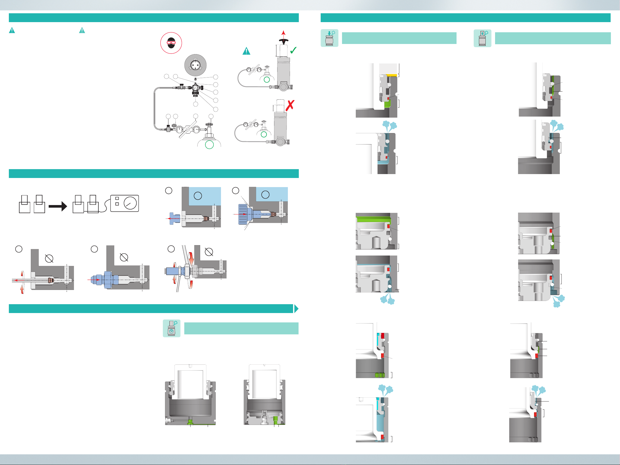
BEFÜLLEN VON GASDRUCKFEDERN / FILLING OF GAS SPRINGS
Beim selbstständigen Befüllen und Entladen nur
Special Springs Equipment verwenden, ansonsten
verfallen Garantie und Haftungsansprüche.
Den auf dem Zylinder angegebenen maximalen
Ladedruck bei 20°C nicht überschreiten.
Anleitung zum Befüllen von Gasdruckfedern mit
Special Springs Equipment
1) Stellen Sie sicher, dass die Kolbenstange vor und
während der Befüllung komplett ausgefahren ist.
2) Spannen Sie die Gasdruckfeder fix ein.
3) Die Verschlussschraube am Zylinder (11) entfernen.
4) Drehgriff (7) losschrauben, bis Stutzen (9) ganz
eingezogen ist.
5) Den Adapter (10) mittels Drehgriff (6) in die
Befüllöffnung der Gasdruckfeder einschrauben.
6) Sicherstellen, dass die Ventile (3-4-8) vollständig
geschlossen sind.
7) Langsam die Ventile von Gasflasche (1) und
Regelarmatur (2) öffnen. Dann den gewünschten
Fülldruck mittels Hebel (H) einstellen.
8) Langsam Ventil (3-4) öffnen, um den Zylinder mit
Druck zu beaufschlagen. Der Fülldruck wird nun am
Manometer (M) angezeigt.
9) Die Ventile (3-4) schließen.
10) Ablassventil (8) öffnen.
11) Den Adapter (10) mit Hilfe von Drehgriff (6) wieder
aus der Befüllöffnung herausdrehen.
12) Die Verschlussschraube (11) wieder in den Zylinder
einschrauben.
13) Das Absperrventil der Stickstoffflasche (1) zudrehen.
For the filling and discharging of gas springs, use
Special Springs components only. Otherwise, the
warranty and any liability claims will become void.
Do not exceed the maximum charging pressure
at 20°C indicated on the cylinder.
Instructions for the filling of gas springs using Special
Springs equipment
1) Ensure that the piston rod is completely extended
before and during the filling action.
2) Fix the gas spring with a clamp to prevent unwanted
movement.
3) Unscrew the screw plug (11) from the cylinder.
4) Unscrew the twist grip (7) until the pin (9) is
completely retracted
5) By turning the twist grip (6), screw the adapter (10)
onto the charging hole of the gas spring
6) Ensure that the valves (3-4-8) are completely closed.
7) Slowly open the valves on the gas bottle (1) and on
the outlet valve (2); then set the pressure with the
lever (H).
8) Slowly open the valve (3-4) to pressurise the cylinder.
The pressure now appears on the pressure gauge
(M).
9) Close the valves (3-4).
10) Open the discharging valve (8).
11) By turning the twist grip (6), unscrew the adapter
(10) from the charging hole.
12) Screw the screw plug (11) into the cylinder.
13) Close the nitrogen bottle valve (1)
IM VERBUND / LINKED SYSTEM
N2
N2
1N2
N2
2
N2
N2
3
N2
N2
4
Dichtung an den Auslaufrillen –
Druckentladung
seal on discontinuity grooves –
pressure exhaust
Maximaler Hub
maximum stroke
Verlängerung der Buchse
bush extension
Auslaufrillen
discontinuity grooves
Dichtung Körper – Buchse
body – bush seal
Auslaufrillen
discontinuity grooves
Auslaufrillen
discontinuity grooves
Auslaufrillen
discontinuity grooves
Deformierbarer Bereich
deformable area
Deformierbarer Bereich
deformable area
Dichtung Körper – Boden
body – bottom plate seal
Dichtung Kolben – Körper
piston – body seal
Dichtung Kolben – Körper
piston – body seal
Dichtung an den Auslaufrillen –
Druckentladung
seal on discontinuity grooves –
pressure exhaust
Dichtung an den Auslaufrillen –
Druckentladung
seal on discontinuity grooves –
pressure exhaust
Dichtung an den Auslaufrillen –
Druckentladung
seal on discontinuity grooves –
pressure exhaust
Verformung
deformed area
Verformung
deformed area
Auslaufrillen
discontinuity grooves
Dichtung Körper – Buchse
body – bush seal
Deformierbarer Bereich
deformable area
Verformung
deformed area
Dichtung an den Auslaufrillen –
Druckentladung
seal on discontinuity grooves –
pressure exhaust
Auslaufrillen
discontinuity grooves
Deformierbarer Bereich
deformable area
Dichtung Körper – Boden
body – bottom plate seal
Dichtung an den Auslaufrillen
seal on discontinuity grooves
Verformung
deformed area
Berststopfen
rupture plug Auslaufrille
discontinuity groove Boden mit integrierter
Berstsicherung
rupture septum
Auslaufrille
discontinuity
groove
SICHERHEITSSYSTEME / SAFETY SYSTEMS
SICHERHEITSSYSTEME / SAFETY SYSTEMS
N2
N2
5
Anzugsdrehmoment der
Schlauchanschlüsse nach
Herstellerangaben
Tightening torques for hose
fittings: see manufacturers‘
instructions
Aktive Überhubsicherung
Over Stroke Active Safety
Aktive Überdrucksicherung
Over Pressure Active Safety
Aktiver Schutz bei unkontrolliertem Rückhub
Uncontrolled Speed Active Safety
1
H
7
49
2
3
6
M
8
11
10
N2
N2
N2
100% Hub/stroke
<100% Hub/stroke
DM
Symbolbild E 6350 Force
Symbolic picture E 6350 Force
Symbolbild E 6350 Force
Symbolic picture E 6350 Force
Symbolbild E 6350 Force
Symbolic picture E 6350 Force
This manual suits for next models
3
Popular Industrial Equipment manuals by other brands

Siemens
Siemens SIRIUS 3TF68 Series operating instructions

POSTPROCESS
POSTPROCESS RADOR quick start guide

Mitsubishi Electric
Mitsubishi Electric BC34 Installation, operation & maintenance manual

Dreve
Dreve Drufomat scan Working instructions

ABB
ABB UC Series Repair guide

Bosch
Bosch rexroth PSK instructions


