PHD PFC Series User manual

PART NO.: 6441-814
1
TEARDOWN AND REBUILD PROCEDURES: SERIES PFC FRAME CLAMPS
PFC TEARDOWN PROCEDURES
TOOLS REQUIRED:
• Vice
• Cleaning towels
• Small flat head screwdriver
and/or brass pick
• 4 mm hex wrench
• 5 mm hex wrench
• 6 mm hex wrench
• 8 mm hex wrench
• 10 mm hex wrench
DISASSEMBLY PROCEDURES (SEE FIGURES 1 & 2):
Ensure that pressurized air has been removed from the
clamp before beginning disassembly procedures.
1) Remove all tooling from jaws.
2) Ensure that clamp is in full closed position and is in vise.
Vise jaws to hold sides of mounting plate (14).
3) Pin retainer removal:
a. Standard clamp: Remove fasteners (21)
and washers (20) from bushing block (5).
b. WC1 option: Remove weld cover fasteners (21)
from bushing block (5) and body (1). Remove weld cover.
4) WC1 option only: Remove fasteners (21) from weld
cover plates (37). Remove weld cover plates (37)
and weld cover gaskets (38).
5) Cover plate removal:
a. Standard clamp: Remove fasteners (21) and
cover plates (13) from both sides of clamp.
b. Position sensing switch option (see Figure 2):
i. Remove fasteners (21) and cover plates (13)
from both sides of clamp.
ii. Remove fasteners (32) and switch housing
assembly from clamp.
iii. Remove dowel pins (31).
iv. If target (29) remains on clamp, remove it.
v. Remove target driver (30).
vi. See below for further disassembly if required.
6) Hold onto each jaw (7A) as pivot pins (17) are removed.
7) Remove roller bearing retaining fasteners (12) and washers (11).
8) Remove roller bearings (8) and pins (18).
9) Jaw teardown:
a. “W” style jaw: Remove grease zerk (7D) from jaw (7A).
b. “L” style jaw: Remove grease zerk (7D), clevis fasteners (7C), and clevis (7B) from jaw (7A).
10) Remove port fitting (36A) from bushing block (5) only. Leave port fitting (36B) in body.
11) Remove bushing block fasteners (19), bushing block (5), and dowel pins (16).
12) Remove o-ring seal (27).
13) Remove bore plug (4) by applying minimal air pressure to port on body (1) or to port fitting (36B).
CAUTION: Use only the minimum air pressure required to release bore plug from body. Ensure bore plug is oriented in a safe
direction or that it is contained when removing with air pressure.
14) Remove o-ring seal (26) from bore plug (4).
15) Turn remainder of assembly over and remove mounting plate fasteners (22B) and mounting plate assembly (14 & 15).
16) Remove fastener (22A). This can be done by using a hex to hold fastener (23) while removing fastener (22A).
17) Remove piston seal (24) from piston (3).
18) To avoid damage, gently remove rod seal (25) if it is to be reused.
19) Twist cam (6) and remaining attached parts (9, 10). Remove from body.
20) Remove links (9) and dowel pin (10) from cam (6).
21) Remove port fittings (36A, 36B).
22) Clean all parts and inspect for wear and damage. Replace if required.
1
2(SEE PAGE 3)
3(SEE PAGE 3)
(SEE PAGE 3)
4
5
8
8
9
9
21
21
21
21
11
12
12
11
20
21
21
20
36A
26
27
24
25
23
18
11
12
12
11
10
6
22A
22B
22B
15
36B
21
13
13
21
7C
7C
7D
7D
JAW B
JAW A
7A
18 7B
19
17
16
7A
7B
14
7A
7D
7A 7D
PFC4TW
PFC4TL
PFC4TW
PFC4TL
PFC4TL
PFC4TL PFC4TW
PFC4TW
OPTIONAL
WELD COVER
REPLACES
ITEM 20
OPTIONAL WELD COVER
REPLACES ITEM 20
WELD COVER
GASKET
ASSEMBLY
37
38
21
TORQUE
TO 50 lb-in
FIGURE 1

PART NO.: 6441-814
2
TEARDOWN AND REBUILD PROCEDURES: SERIES PFC FRAME CLAMPS
POSITION SENSOR DISASSEMBLY:
1) Remove fastener (33A). This will free amplifier box (33B) from switch housing (28).
2) Remove fasteners (35) and remaining switch components (33C, 33D, & 34) from switch housing (28).
3) To remove the switch “chicklet” (33C) from the adjustment bar (34):
a. Note that the switch pins (33D) protrude from the adjustment bar (34) on the opposite side of the switch chicklet (33C). Set this
assembly on a surface so the chicklet (33C) is facing upward. Press down on the adjustment bar (34). This will lift the chicklet
(33C) off of the adjustment bar (34) slightly.
b. Using pliers or a small, flat screwdriver, cautiously rock the chicklet (33C) off of the adjustment bar (34) to avoid damage to plastic
switch pin (33D).
c. NOTE: Switch pins (33D) may remain in adjustment bar (34). If this occurs,
simply use pliers and gently remove them from the adjustment bar (34) to avoid damage.
4) Clean all components and inspect for wear and damage. Replace if required.
PFC REBUILD PROCEDURES
TOOLS REQUIRED:
• Copy of assembly prints (see Figures 1-4)
• Vice
• Cleaning towels
• Degreasing agent
• Small flat head screwdriver and/or brass pick
• 4 mm hex wrench
• 5 mm hex wrench
• 6 mm hex wrench
• 8 mm hex wrench
• 10 mm hex wrench
• Loctite 272 or equivalent
• Magna-lube G-NLGI #2 consistency or equivalent
• Nye Rheolube 368AX-1 or equivalent
• Grease gun (filled with Nye Rheolube 368AX-1
or equivalent grease)
NOTES:
1) All parts are to be clean and free of debris.
2) Thread locker (Loctite 272) required only on P&R assembly. All other threads are self locking.
3) Use only lubricants specified or their equivalent.
4) Use care to avoid damage to any part during assembly.
5) Item numbers referred to in procedures are from assembly prints.
LUBRICATION GUIDELINES (MAGNA-LUBE) - SEE FIGURE 1
ITEM DESCRIPTION LOCATION LUBE PER
1 BODY BORE, ROD SEAL GROOVE
15973-01
2 PISTON ROD O.D.
3 PISTON PISTON SEAL GROOVE, PISTON O.D.
4 BORE PLUG SEAL GROOVE, MANIFOLD SEAL SURFACE
24 ROD SEAL —
25 PISTON SEAL —
26 CAP SEAL —
27 MANIFOLD SEAL —
LUBRICATION GUIDELINES (NYE RHEOLUBE) - SEE FIGURE 1
ITEM DESCRIPTION LOCATION LUBE PER
1 BODY SLIDER SLOTS
15973-30
5 BUSHING BLOCK PIVOT I.D.S AND SURFACES THAT MATE WITH JAWS
6 CAM SURFACES THAT MATE WITH ROLLER BEARINGS,
LINKS, AND BODY SLOTS
7A JAW PIVOT I.D.
7B CLEVIS BEARING I.D. & SURFACES THAT MATE WITH LINKS
8 ROLLER BEARINGS I.D. & O.D.
9 LINK I.D.S AND LARGE FLAT SURFACES
10 DOWEL PIN O.D.
17 DOWEL PIN O.D.
18 DOWEL PIN O.D.
NOTE: AFTER FINAL ASSEMBLY - APPLY ADDITIONAL BLOB OF LUBE ON ROLLER BEARING
O.D. AND FILL GREASE ZERKS UNTIL LUBE IS VISABLE BETWEEN JAW AND BUSHING BLOCK
POSITIONAL SWITCH ASSEMBLY (SEE FIGURE 2)
TORQUE
ITEM QTY DESCRIPTION in-lb
13 2 PLATE; COVER —
21 8 SHCS (M6 x 10) 125
28 1 HOUSING; SWITCH —
29 1 TARGET —
30 1 DRIVER; TARGET 200
31 2 PIN; DOWEL (6 x 12) —
32 2 SHCS (M6 x 20) 125
33 1
SWITCH
—
33A 1 44
33B 1 —
33C 2 —
33D 4 —
34 2 BAR; ADJUSTMENT —
35 2 SHCS (M5 X 10) 44
28
29
30
31
33B
34
34
35
35
32
21
13
33A
NOTE TARGET
ORIENTATION
33D
33D
33C
33C
DETAIL A
A
LUBRICATION AND LOCTITE GUIDELINES
FIGURE 2

PART NO.: 6441-814
3
SUB-ASSEMBLY PROCEDURES
BOTTOM PLATE ASSEMBLY (SEE FIGURE 3):
1) Press 2X dowel pins (15) into mounting plate (14) until 0.300 in [7.6 mm] remains visible.
SWITCH HOUSING SUB-ASSEMBLY (IF REQUIRED):
1) Insert switch pin (33D) into switch chicklet (33C) until seated.
2) Taking care to avoid damage to switch pins (33D), insert chicklet and pin assembly (33C & 33D) into adjustment bar (34) noting
orientation of chicklet assembly (33C & 33D) to adjustment bar (34).
3) Assemble switch amplifier box (33B) to switch housing (28) using fastener (33A). Tighten fastener (33A) to 44 in-lb [4.97 Nm].
4) Assemble chicklet and adjustment bar sub-assembly (33C, 33D, 34) into switch housing (28) noting orientation and designation of
switch as shown in Figure 2. Also note cable routing shown in Figure 2. NOTE: CABLES MUST NOT BE ABLE TO ENTER TARGET SLOT
AREA. Insert fasteners (35) through switch housing (28) and into thread of adjustment bar (34). Hand tighten only. Final tightening
will be done when switches are adjusted.
PISTON AND ROD ASSEMBLY (SEE FIGURE 4):
1) Clean piston (3), piston rod (2), and P&R fastener (23). These parts must be clean and free of oils/grease to ensure bond.
2) Apply Loctite 272 or equivalent adhesive to the P&R fastener (23) on thread and around the head of the fastener.
3) Insert fastener (23) through piston (3) and into piston rod (2). Tighten as tight as possible by hand. Remove any excess adhesive.
NOTE: Final torque of fastener (23) will be done later.
NOTE: Do not assemble P&R until ready for total assembly of clamp.
JAW ASSEMBLY
See Figure 1.
“W” JAW ASSEMBLY (2 JAWS TOTAL):
1) Insert grease zerk (7D) into jaw (7A) and tighten to 30 in-lb [3.39 Nm].
“L” JAW ASSEMBLY (2 JAWS TOTAL):
1) Place key of clevis (7B) into slot of jaw (7A) noting orientation of threads on side of clevis (7B).
2) Insert clevis fasteners (7C) through jaw (7A) and into clevis (7B). Tighten to 600 in-lb [67.8 Nm].
3) Insert grease zerk (7D) into jaw (7A) and tighten to 30 in-lb [3.39 Nm].
COMPLETE ASSEMBLY (SEE FIGURE 1):
1) Using Magna-Lube G or equivalent lubricant, lubricate the following:
a. Piston bore and rod seal groove of body (1).
b. Rod seal (25) completely.
2) Insert rod seal (25) into rod seal groove of body (1) noting orientation of seal.
3) Using Nye Rheolube or equivalent lubricant, lubricate the following:
a. Lubricate slider slot of body (1).
b. Lubricate cam (6), dowel pin holes, and surfaces that will
mate with body and roller bearings.
c. Dowel pin (10) and links (9) completely.
TEARDOWN AND REBUILD PROCEDURES: SERIES PFC FRAME CLAMPS
LOCTITE GUIDELINES (272) - SEE FIGURE 4
ITEM DESCRIPTION LOCATION APPLY PER
23 SHCS; PISTON AND ROD ON THREAD & ON HEAD (SEE FIGURE 4) 15974-24
PREPARATION PROCESS PRIOR TO LOCTITE
SFHCS (23) TO BE FREE OF ANY
OILS OR CONTAMINANTS. CLEAN WITH
DEGREASER AND DRY THOROUGHLY
PRIOR TO APPLYING LOCTITE.
PISTON (3) TO BE FREE OF ANY
OILS OR CONTAMINANTS ON SURFACES
THAT MATE WITH SFHCS (23) AND
PISTON ROD (2). CLEAN WITH
DEGREASER AND DRY THOROUGHLY
PRIOR TO ASSEMBLY.
PISTON ROD (2) TO BE FREE OF ANY
OILS OR CONTAMINANTS ON SURFACE
THAT MATES WITH PISTON (3) AND
INTERNAL THD THAT MATES WITH
SFHCS (23). CLEAN WITH DEGREASER AND
DRY THOROUGHLY PRIOR TO ASSEMBLY.
LUBRICATION GUIDELINES (NYE RHEOLUBE) - SEE FIGURE 2
ITEM DESCRIPTION LOCATION LUBE PER
28 SWITCH HOUSING TARGET SLOT
15973-3029 TARGET I.D. AND OUTSIDE SURFACES
30 TARGET DRIVER O.D.
MOUNTING PLATE ASSEMBLY
14
15 PRESS TO
DIMENSION SHOWN
2X 0.30
FIGURE 3
FIGURE 4

PART NO.: 6441-814
4
COMPLETE ASSEMBLY (CONTINUED):
4) Insert dowel pin (10) into cam (6) as shown.
5) Assemble links (9) onto dowel pins (10) as shown.
6) Twist cam (6) and insert protrusions into slider slots in body (1).
7) Using Magna-Lube G or equivalent lubricant, lubricate the following:
a. Piston (3) in seal groove and around outside diameters.
b. Piston seal (24) completely.
8) Insert piston seal (24) into seal groove of piston (3) making sure seal is not twisted.
9) Insert piston and rod sub-assembly (2, 3, 23, 24) into body passing piston rod (2) through piston rod seal (25) until piston seal is in
bore of body (1). Continue to insert piston and rod assembly to bottom of bore with links (9) oriented as shown.
10) Insert fastener (22A) through cam (6) and into piston rod (2). Hold fastener (23) rigid with hex wrench, tighten fastener (22A)
to 700 in-lb [79.09 Nm]. Wipe away any excess adhesive from piston (3) and fastener (23).
11) Insert dowel pins (16) into holes of body (1).
12) Using Magna-Lube G or equivalent lubricant, lubricate the following:
a. Seal groove and manifold seal surface of bore plug (4).
b. O-ring seal (26) completely.
c. Manifold seal (27) completely.
13) Insert o-ring seal (26) into groove of bore plug (4) and insert this assembly onto body (1) noting orientation of dowel pins (16) and
port of bore plug (4). An arbor press is recommended only to keep body (1) and bore plug assembly (4, 26) oriented parallel to each
other. Press until bore plug assembly (4, 26) is seated in body (1).
14) Insert manifold seal (27) in manifold seal cavity of bore plug (4).
15) Place bushing block (5) onto body (1) aligning port and dowel pin holes with dowels (16).
16) Insert bushing block fasteners (19) through bushing block and thread into body (1). Tighten to 300 in-lb [33.9 Nm].
17) Using Nye Rheolube or equivalent lubricant, lubricate the following:
a. Bushing block (5) pivot pin holes and surfaces that will mate with jaws
b. Jaw (7A) pivot pin holes
c. Pivot dowel pins (17) completely
d. Clevis (7B) bearing pin holes and surfaces that will mate with links (roller bearing pin holes on jaw (7A) for “W” style jaw)
e. Roller bearing (8) completely
18) Aligning pivot pin hole on bushing block (5) with pivot pin hole of jaw (7A) of finished jaw sub-assembly, insert pivot dowel pins (17)
through both bushing block (5) and jaw (7A).
19) Align slot of link (9) with bushing pin hole of clevis (7B). Insert roller bearing dowel pin (18) just enough to hold link in place.
20) Align hole of roller bearing (8) to roller bearing dowel pin (18) and push pin in enough to hold roller bearing in place.
21) Align slot of second link (9) to roller bearing dowel pin (18) ensuring that links (9) and roller bearing (8) are all inside legs of clevis
(7B) and push roller bearing dowel pin (18) until end is flush with edge of clevis (7B).
22) Insert washer (11) and fastener (12) on each side of clevis (7B). Tighten fastener to 85 in-lb [9.6 Nm]. Do this step on each
jaw assembly.
23) Using Nye Rheolube or equivalent lubricant, apply lube to grease zerk (7D) of jaw (7A). Continue to apply lube until it is visible around
pivot dowel pins (17). Wipe away any excess lube.
24) Pivot pin retaining:
a. Standard clamp: Insert washer (20) and fastener (21) on each side of bushing block (5). Tighten fastener to 125 in-lb [14.1 Nm].
Do this for both pivot pins (17).
b. WC1 option: Place optional weld cover over jaw (7A) and bushing block (5) aligning holes/slots with threads in bushing
block (5) and body (1). Insert fasteners (21) through weld cover into threads of bushing block (5) and body (1). Tighten
fasteners to 125 in-lb [14.1 Nm].
25) For units with WC1 option, insert weld cover gasket (38) and weld cover plate (37) into bushing block (5) aligning holes with threads
in bushing block (5). Insert fasteners (21) and tighten to 50 in-lb [5.65 Nm].
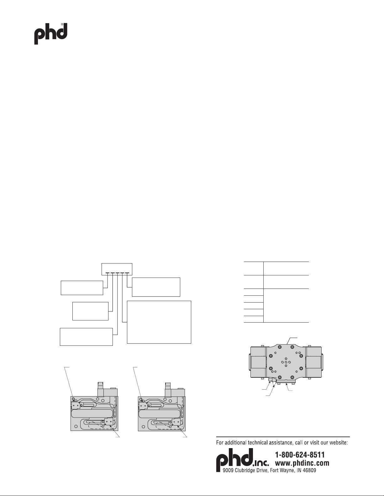
26) Front cover/switch assembly (see Figure 2, page 2):
a. Standard clamp: Insert cover plate (13) and fasteners (21). Tighten fasteners to 125 in-lb [14.1 Nm]. Do this on both sides of clamp.
b. For positional sensing option:
i. Insert target driver (30) into thread of cam (6) on side of clamp where switch is to be. Tighten to 200 in-lb [22.6 Nm].
ii. Using Nye Rheolube or equivalent lubricant, lubricate the following:
1. Target driver (30) outside diameter
2. Target (29) completely
3. Switch housing (28) target slot
TEARDOWN AND REBUILD PROCEDURES: SERIES PFC FRAME CLAMPS

PART NO.: 6441-814
5
COMPLETE ASSEMBLY (CONTINUED):
iii. Insert dowel pins (31) into body (1).
iv. Insert target (29) into target driver (30) noting target orientation.
v. Assemble switch housing assembly aligning dowel pin holes of switch housing (28) to dowel pins (31).
vi. Insert switch housing mounting fasteners (32) through switch housing (28) and into threads of body (1). Tighten fasteners to
125 in-lb [14.1 Nm].
vii. Adjust switches as noted below (SETTING SWITCHES).
viii. Insert cover plate (13) and fasteners (21) into threads in switch housing (28). Tighten fasteners to 125 in-lb [14.1 Nm].
ix. Insert cover plate (13) and fasteners (21) into threads in body (1). Tighten fasteners to 125 in-lb [14.1 Nm].
SETTING SWITCHES:
1) Switches to be set after tooling has been mounted.
2) Jaws to be opened and closed using normal operating air pressure.
3) Power to switch is required.
a. Open direction:
i. Pressurize jaws open port.
ii. Loosen left adjustment screw (35) enough to move switch as far as it can move upward toward jaw tooling.
iii. Adjust switch slowly in downward direction, towards mounting plate (14), until switch turns on. Tighten adjustment screw
to 44 in-lb [5.0 Nm].
b. Closed direction:
i. With jaw tooling mounted and with part between jaws, pressurize jaws close port.
ii. Loosen right adjustment screw (35) enough to move switch as far as it can move downward, toward mounting plate (14)
until it stops.
iii. Adjust switch slowly in upward direction, toward jaw tooling, until switch turns on. Tighten adjustment screw
to 44 in-lb [5.0 Nm].
c. Check for proper switch adjustment by opening and closing jaws. If switches are not activating properly, readjust switches and
check again.
TEARDOWN AND REBUILD PROCEDURES: SERIES PFC FRAME CLAMPS
OPTION
CODE
QUICK DISCONNECT
PIN NUMBER
PSxAx S01 = PIN 5
S02 = PIN 4
PxxDx
S01 = PIN 4
S02 = PIN 2
PxxEx
PxxFx
PxxHx
PxxJx
SIDE 3
PS(R)xx1
PS(R)xx9
SIDE 1
(PORT SIDE)
NOTE: POSITIONAL SENSOR MAY BE
MOUNTED ON SIDE 1 OR SIDE 3
Px1xx = SIDE 1 (SHOWN)
Px3xx = SIDE 3
PSxxx PRxxx
SWITCH SATELLITE “S01”
IN THIS LOCATION
(JAWS CLOSED SENSOR)
SWITCH SATELLITE “S02”
IN THIS LOCATION
(JAWS CLOSED SENSOR)
SWITCH SATELLITE “S02”
IN THIS LOCATION
(JAWS OPEN SWITCH)
SWITCH SATELLITE “S01”
IN THIS LOCATION
(JAWS OPEN SWITCH)
POSITION SENSOR OPTION CODE
Pxxxx
SENSING OPTION
S- Standard
R- Reversed
HOUSING OPTION
P- Positional Sensing
SWITCH OPTION
N- No Switch
A- 5-pin AC/DC Switch (Turck)
D- 4-pin PNP DC Switch (P + F)
E- 4-pin PNP DC Switch (Turck)
F- 4-pin PNP DC Switch (Efector)
H- 4-pin NPN DC Switch (P + F)
J- 4-pin NPN DC Switch (Turck)
CONNECTOR POSITION
1- Parallel to jaws
9- Perpendicular to jaws
SWITCH HOUSING OPTION
1- Position 1 (Port Side)
3- Position 3

PART NO.: 6441-814
6
TEARDOWN AND REBUILD PROCEDURES: SERIES PFC FRAME CLAMPS
PFC4TL PFC4TW
PART NUMBER PART NUMBER TORQUE
OPTION ITEM QTY DESCRIPTION IMPERIAL METRIC IMPERIAL METRIC in-lb
1 1 BODY 73104-01 73104-02 73104-01 73104-02 —
2 1 ROD; PISTON 73111-01 — —
3 1 PISTON 73126-01 — —
4 1 PLUG; BORE 73105-01 — —
5 1 BLOCK; BUSHING 73102-01 73102-02 73102-01 73102-02 —
6 1 CAM 73109-01 73109-02 —
7A 2 JAW 73107-01 73131-02 —
7B 2 CLEVIS 73108-01 N/A —
7C 4 SHCS (M12 x 40) 14308-196 N/A 600
7D 2 ZERK; GREASE 63086 — 30
8 2 BEARING; ROLLER 63080 — —
9 4 LINK 73110-02 — —
10 2 PIN; DOWEL (12 x 60) 17831-135 — —
11 4 WASHER; CSINK 73119-001 — —
12 4 SFHCS (M6 x 12) 14308-001 — 85
13 2 PLATE; COVER 73113-01 — —
14 1 PLATE; MOUNTING 73112-01 — —
15 2 PIN; DOWEL (8 x 24) 17831-104 — —
16 2 PIN; DOWEL (8 x 16) 17831-039 — —
17 2 PIN; PIVOT (1 x 5) 3696-098 — —
18 2 PIN; ROLLER BEARING (16 x 55) 17831-147 — —
19 8 SHCS (M8 x 30) 14308-026 — 300
20 4 WASHER 70365-002 — —
21 8* SHCS (M6 x 10) 14308-114 — 125 / 50*
22A 1 SHCS (M12 x 30) 14308-194 — 700
22B 4 SHCS (M12 x 30) 14308-194 — 700
23 1 SFHCS (M12 x 25) 14308-633 — 700
24 1 SEAL; PISTON 3642-052-1 — —
25 1 SEAL; ROD 62827-009-1 — —
26 1 SEAL; BORE PLUG 3642-052-1 — —
27 1 SEAL; MANIFOLD 1950-111-1 — —
B001 5 1 BLOCK; BUSHING, -B001 73102-11 — 73102-11 — —
WC1
20 2 COVER; WELD 73118-01 73118-02 —
37 2 PLATE; WELD COVER 73127-01 — —
38 2 GASKET; WELD COVER 73128-01 — —
LAA 36A 1 FITTING; PORT, LAA 62178-010 62195-010 62178-010 62195-010 60
36B 1 FITTING; PORT, LAA 62178-010 62195-010 62178-010 62195-010 60
LBB 36A 1 FITTING; PORT, LBB 71120-002 71121-002 71120-002 71121-002 60
36B 1 FITTING; PORT, LBB 71120-002 71121-002 71120-002 71121-002 60
*NOTE - QTY = 20 WITH WELD COVER OPTION. TORQUE WELD COVER GASKET ASSEMBLY SHCS TO 50 lb-in
(SEE WELD COVER GASKET ASSEMBLY VIEW)
PARTS LIST (SEE FIGURE 1)
Table of contents
Other PHD Industrial Equipment manuals