MexAir RC E-Banshee User manual

E-Banshee Manual MexAir RC PH: 315.532.6826
www.mexairrc.com
1
50 " Wingspan
332 Square Inch Main Wing
3-Channel Electric Sport, Free Flight, or SAM "Legal" Construction
The E-BANSHEE
Based on Leon Shulman's Famous 1941 Banshee
Cover Photo - Courtesy of the Shulman Family
http://shulmanaviation.com/

E-Banshee Manual MexAir RC PH: 315.532.6826
www.mexairrc.com
2
Introduction
This manual is intended to supplement details provided on the E-Banshee plan sheet. A
seasoned model builder may be able to construct the E-Banshee using only the plans and
previous experiences in model construction. In providing this supplement, we have assumed
that the builder is a novice with little or no prior building experience. We include suggested
construction steps, detailed pictures, and other information that may be useful to the beginner
and seasoned modeler alike. The details of accessory assemblies, recommended electronics,
and hardware and construction materials are described throughout this manual.
In addition to the kit version described herein, a “short kit” is also available. The "short kit"
includes the necessary laser cut pieces and machined small parts (user supplies standard balsa
strips and hardware available from any good R/C hobby shop). Consult the Appendices for
supplemental information and variations.
The E-Banshee kit may be built as a fully radio controlled (R/C) electric powered sport model. In
addition, it can also be constructed as a Free-Flight (FF) model, and may be modified as a SAM (Society
of Antique Modelers) "legal" model for SAM competition. Each variation is shown on the plans and is
further described herein.
Recommended Motors:
In keeping with modern construction techniques, the model has been designed to accept any variety of
rear-mount brushless motors. The motor may be mounted with a typical aluminum mount (supplied
with many motors), or directly from the motor housing rear through the plywood firewall. Motor
selection is left to the builder based on individual preferences and availability.
Servos:
Two mini/micro servos are used for rudder and elevator control. High torque is not required as the
control surfaces are not oversized. A good recommended torque would be 18 to 22 oz-in. A short servo
arm is necessary (usually supplied with servo). A removable electronics platform assembly is supplied
with the kit. We recommend the use of the platform assembly although there are many other ways that
the servos may be placed and mounted. Use of the assembly also provides additional support for the
motor mount / firewall. The servo mount will fit most mini/micro servos.
Battery Compartment:
A large battery compartment is integral to the design. Since the E-Banshee center of gravity (CG) is
approximately 1/2 way back from the wing leading edge, and that the fuselage has a long "moment
arm", it will be necessary to place the battery as far forward as possible and into the nose section. If
necessary, the builder should modify the "as supplied" parts to provide sufficient air cooling to the
battery compartment volume. Cooling flow holes may be placed in the nose block and/or battery
compartment sides, with air exit holes placed in the battery compartment hatch cover. There is more
than sufficient room in the battery compartment to also place the receiver and motor speed control.

E-Banshee Manual MexAir RC PH: 315.532.6826
www.mexairrc.com
3
Kit Contents
The following table can be used as a reference in identifying each part. The plans identify parts using
the same designations as in this table. If not identified with "Sheet #" or as "Loose" - the listed parts are
supplied in stick bundles. Laser cut sheet panels are designated with a "P#" in the table.
Banshee
Parts List
Part
Size
Plan #
Req/Plane
Sheet #
BODY
Crutch
F-1A / F1B
1
P1
Pylon
F-2
1
P4
Pylon Rear
F-3
1
P4
Lower Body
F-4 / F-4 Rear
1
P1 / P3
Side Panel
F-5
2
P5
Former
F-6
1
P5
Former
F-7
2
P5
Former
F-8
1
P4
Former
F-9
1
P4
Former
F-10
2
P4 / P5
Former
F-11
2
P3
Former
F-12
2
P5
Former
F-13
2
P4 / P5
Former
F-14
1
P5
Former
F-15
2
P4 / P5
Floor Mtr
Compartment
F-16
1
Loose
Mtr Mount
F-17
1
Loose
LG Block
F-18
1
Loose
Hatch Cover Stop
F-19
1
Loose
Pylon Angle Block
Triangle Stock
F-20
4
Loose
Bottom Stringer
1/8X1/4X8-1/2
2
Dowel
3/16X2-5/16
2
Loose
Nose Blocks
F-21
8
P2
Hatch Cover
1/16X1-7/16 X5-1/16 Ply
HC
1
Loose
Body Wing Saddle
WM
2
P1
Wire, LG
3/32"
1
Loose
Tube, Brass
3/32"ID, 1/8"OD
1
Loose
F-9 Lining
1/8X1/8X8"
Hardwood Strip
1

E-Banshee Manual MexAir RC PH: 315.532.6826
www.mexairrc.com
4
ELEV &
RUDDER
Sub-Rudder
E-1
2
Loose
Elev Tip
E-2
2
Loose
Elev Rear Center
E-3
1
Loose
Fin
R-1
1
P1
Fin
R-2
1
P5
RIBS &
WINGS
W-1
W-1
2
P3
W-1A
W-1A
2
P6
W-2
W-2
2
P6
W-3
W-3
2
P6
W-4
W-4
2
P6
W-5
W-5
2
P6
W-6
W-6
2
P6
W-7
W-7
2
P6
W-8
W-8
2
P6
W-9
W-9
2
P6
W-10
W-10
2
P6
W-11
W-11
2
P6
W-12
W-12
2
P6
LE Inner
1/4X1/4X14
W-13
2
LE Outer
1/4X1/4X11
W-14
2
Trailing Edge Inner
3/16X3/4X14-1/2
W-15
2
Trailing Edge Outer
3/16X3/4X12
W-16
2
Spar- Inner
1/8X1/4X14
W-17
4
Spar- Outer
1/8X1/4X10-1/16
W-18
4
Wing Tip
W-19
2
P2
Wing Tip Angle
Brace
W-20
2
P2
Wing Plate
WM-1
2
P3
Center Wing Sheet
1/16X1-1/8X9
Pkg of 3
Pcs = 9"
Loose
Spar Webbing
1/16X3/4X2
24
P6
Gusset Material
Made From Scrap
Polyhedral Inner
Brace
W-21
1
Loose
Polyhedral Outer
Brace
W-22
2
Loose
ELEVATOR
Trailing Edge
3/16X1/2X9
2
Main Spar
1/4X3/8X22
1
Elev Spar & Side
1/4X3/8X12
2

E-Banshee Manual MexAir RC PH: 315.532.6826
www.mexairrc.com
5
Piece
LE
1/4X1/4X12
2
LE
1/4X1/4X5 ("Filler")
1
Center Section
3/8X1/2X3-1/8
1
Loose
Ribs
1/16X3/8X24
24+ Inch
Random Length
Ribs
1/8X3/8X20
20+ Inch
Random Length
RUDDER
Strip
1/8X3/8X6
1
P1
Strips
1/8X1/4X12
1
Servo Tray
EM Assembly
1
EM Precut
Ply
Hardware
See Note Below *
Many parts will be supplied in their laser cut sheets designated by a P#. All others will be "precut loose"
in suitable packaging or supplied as bundled "sticks".
* Supplied hardware may vary slightly from that pictured. Not all hardware will be used, depending on
building preferences.
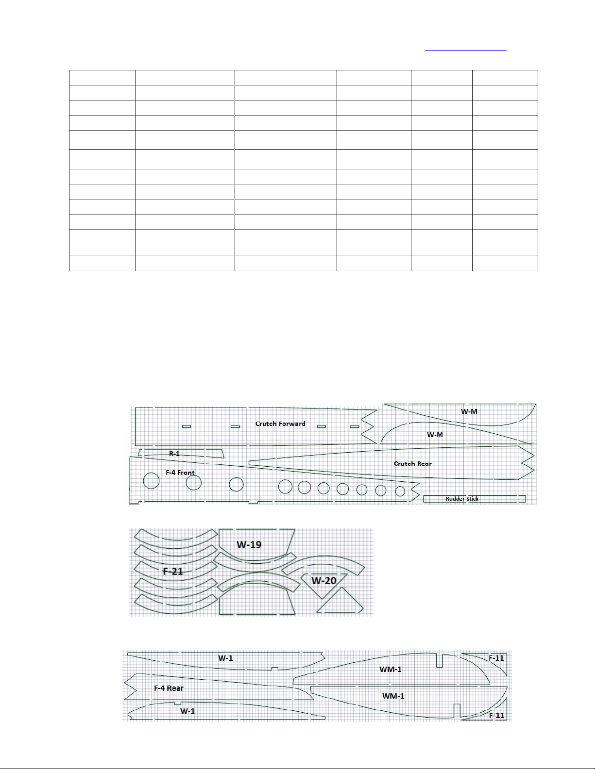
The following "screen shots" are representative of the various sheet-supplied
panels
P1
P2
P3

E-Banshee Manual MexAir RC PH: 315.532.6826
www.mexairrc.com
7
Assembly
The following assembly sections are used as a guide and may be performed independently of each
other. The plans show sufficient and additional details and directions for stabilizers, rudder, and other
assembly pieces that are not described in detail below. Study the plans and plan notes to become
familiar with the part layout and structure. Inventory all parts against the supplied parts list. Should
there be any missing or defective part, contact MexAir R/C for replacements.
General Guidelines:
When removing laser cut balsa parts from their respective sheets, use a sharp hobby knife or
razor blade to score the tabs for clean removal. On occasion, a panel may not be cleanly cut
through and may require additional scoring for clean removal. For plywood sheets, a sharp
blade or fine bladed hobby saw may be used - but may not be necessary as the parts can be
gently manipulated to break the attachment points. Any browning from the laser may be
removed using very fine sandpaper, if desired. The browning does not affect constructability -
and is only superficial. Similarly, any bar-coding on balsa may be lightly sanded off - if desired.
Work on a flat surface to assure proper alignment of assemblies. Use medium or thick CA for
joining all parts, unless otherwise recommended (such as thin CA for wing rib assembly).
Dry fit and sand parts, if necessary, to obtain tight fits between parts.
Work surface may be covered with a sheet of thin clear plastic film to prevent CA from sticking
directly to work surface.
Steps may contain useful hints to assist in proper assembly. Read each step - including
associated "hints" prior to joining parts.
Always first drill pilot holes for installation of self tapping screws into plywood and hardwoods.
A. Wing Assembly: - Inner Wing Assemblies
On flat surface - Follow plan layout. All gluing at tightly fitted joints can use thin CA.
1. Glue W-17 (lower inner spar) to slot of WM-1.
2. Bevel WM-1 top leading edge at 45 degree angle to fit W-13.
3. Glue W-13 to bevel of WM-1 and to leading edge of rib W-1A then Glue W-1A to WM-1.
4. Place scrap balsa spacers under ribs as needed to assure ribs are fully seated in spar when glued
in place. Continue adding ribs W-2 through W-8.
5. Glue upper inner spar (W-7) to ribs with slight excess passing over wing C/L.
6. Bevel the bottom of W-1 to tilt approximately 4 degrees for inner polyhedral. The inner angle
tool (provided in kit) can be used as a guide. Glue W-1 in place.
7. Layout inner trailing edge W-15 to rib trailing edges and interfaces at WM-1. Bevel / sand rib
trailing edges to fit flush with W-15 and WM-1 interface. Minimal sanding should be required to
maintain proper wing form. Glue W-15 in place with sufficient excess length toward inner and
outer sides. This excess will be trimmed off later when joining wing sections.
Repeat for second inside wing assembly.

E-Banshee Manual MexAir RC PH: 315.532.6826
www.mexairrc.com
8
B. Wing Assembly: - Outer Wing Assemblies
Assembly is similar to inner wing assembly, with differences noted.
1. Cut a 2" long 45 degree flat on W-14 to fit W-19 and W-20 at the wing tip. See Inset #1 Below.
2. Glue W-19 to W-20.
3. Glue W-19/W-20 to the flat of W-14.
4. Place (do not glue yet) the outside bottom spar (W-18) in position against and at the bottom of
W-19. Starting with W-9 eight inches from the inside of W-19, glue W-9 through W-12
approximately 2" apart from each other to W-18 while at the same time gluing rib leading edges
to W-14. Assure a tight and proper alignment of the rib leading edge against the 1/4X1/4"
leading edge.
5. Glue the outside upper spar (also designated as W-18) to the ribs. Trim/sand the slight excess at
the tip of W-18 to fit flush with the inside edge of W-19 when pinched downward on top of the
lower spar. While pinching both spars together at W-19 and keeping the bottom spar parallel to
the flat surface, glue the upper spar in place on top of the lower spar and to the inside edge of
W-19.
6. Layout the outer trailing edge (W-16) to rib trailing edges and W-19. Bevel/sand the trailing
edge of W-19 and trailing edges of the ribs to fit flush with W-16. Minimal sanding should be
required to get a flush fit.
7. Glue W-16 in place with sufficient excess at both the inner and outer sides (to be trimmed upon
final wing assembly).
Repeat for second outside wing assembly.
W-14 Leading Edge
"Flat" Carved 2" From End
W-19
Inset #1

E-Banshee Manual MexAir RC PH: 315.532.6826
www.mexairrc.com
9
C. Final Wing Assembly
This step requires the cutting and removal of thin portions of wing ribs to insert
polyhedral braces. Always use a sharp hobby knife or razor blade to remove a minimal
amount of material to assure a flush fit.
1. Layout all four wing sections along a straight line at the leading edges. Align adjacent
intersecting leading and trailing edges and trim the excess overlaps while leaving
enough excess to later bevel the edges for the proper polyhedral fit. Use the plan
polyhedral diagrams as a guide.
2. Trim a 1/8" sliver from W-8, adjacent to the spars. Dry-fit the outer polyhedral brace
(W-22) into the slot and adjacent to rib W-7. Note that the tip edge of W-22 is less wide
than the inside edge of W-22. If necessary, sand the brace at the end for a flush fit with
W-7.
3. Lay the inner wing section on a flat surface and position the outer wing tip 3-1/2" off the
table. Trim/bevel any excess at the wing outer and inner assembly interfaces so as to
properly set the correct polyhedral angle while maintaining a straight leading edge
profile. Trim /sand any excess from W-22 where it should fit flush with rib W-9.
4. When satisfied with fitting, glue W-22 in place and glue all interfacing joints while
maintaining the proper polyhedral angle.
5. Similar to step 2 above, cut a 1/8" sliver from ribs W-1 and W-1A to fit polyhedral brace
W-21. W-21 fits in place at the centerline when the wing halves are joined later.
Trim/sand any excess at the interface with W-2 to assure a flush fit. Do not glue W-21 in
place at this time.
6. Repeat steps 2 through 5 for the other wing half.
7. Place both wing halves together at the W-1 interfaces. Verify proper bevel when fitted
together. Use the polyhedral diagram on the plans and W-21's precut shape as a guide.
If necessary, sand the W-1 interface to get the proper angle. The "center angle tool"
supplied with the kit can also be used as a guide by simply laying each wing inner
section flat and placing the tool against W-1. W-1's side should tilt outward at the top
at the same 94 degree angle (4 degrees from vertical) as the edge of the tool.
8. When satisfied with the fit, use slow cure medium or thick CA to join both wing halves
together at the W-1 interface. Be sure to also glue W-21 securely in place at this time
while maintaining the proper polyhedral angle. Verify proper polyhedral angle prior to
glue setting.
9. When all glue has set, invert the wing assembly. Apply thin CA to the seam formed at
the WM-1 interface. Allow sufficient wicking of the CA into the joint.
10. Add spar webbing. Trim excess at ends to fit flush with wing ribs. Note that webbing
from W-2 to W1-A and between W1-A and W-1 are two separate pieces cut from one
web piece. Do not cut through W1-A to fit a single web from W-2 to W-1.
11. Add wing braces as shown on plans. Scrap balsa 1/8" (or thicker) can be used.
12. Add 1/16" top wing sheeting overlapping beyond the edges of W1-A. Sheeting should
go from the apex of the leading edge to the back of the trailing edge. The surface
profile at leading and trailing edges should be sanded/feathered prior to covering the
wing.
13. Trim/sand excesses beyond the wing tips and spar tops/bottoms. Sand the balance of
wing assembly and contour to final shape.

E-Banshee Manual MexAir RC PH: 315.532.6826
www.mexairrc.com
10
D. Fuselage Assembly - the fuselage is assembled using the plan as a guide. The order of assembly can
vary depending on the builder. Study the plans and dry-fit parts prior to gluing. We recommend a
basic assembly sequence as follows:
1. Prior to removing F-9 from its panel, cut the hardwood strip lining into the four pieces to frame
the opening using the plan as a guide. The uppermost piece will provide the ledge that will
support the motor mount base (F-16). Glue the strips to the F-9 "frame" as shown on plans.
2. On a flat surface, glue F2 to F-3. Similarly, glue F-4 to "F-4 rear" and F-1A to F-1B.
3. Align F-2 to crutch F-1 slots.
4. Assemble / glue in place F-6, F-7, F-1, F2, F10, F-12, and F-14 maintaining vertical, horizontal,
and perpendicular alignments.
5. Bevel center edge of W-M's to fit flush and at the proper angle when placed on the top of F-6
and F-7's. Assure a flush fit at the pylon interface. Sand interfacing edges as necessary. Glue
W-M's in place and wick thin CA into the W-M interfacing joint.
6. Invert the assembly. Similar to step 3 above, add F-4, F-11, and F-13.
7. Add F-8, F-9, and F-5's, to Crutch as shown on plans. Dry-fit F-5's to the F-8 and F-9 sides onto
the Crutch holding the assembly together with masking tape. The F-9 hardwood strip lining
faces forwards {see plans for details}. Adjust as necessary for proper alignment and fit. Spot
glue in place and then remove tape and complete gluing using thin CA, wicked between joints.
8. The front nose piece is made from the eight F-21 nose pieces by first gluing the eight pieces
together - side-to-side. Careful alignment must be maintained during gluing. The sides of the
glued assembly are then cut/contoured to fit neatly into the forward opening between the
perimeter formed by F-5's, F-18, and the forward/bottom of F-16. Work slowly and work
carefully to obtain the correct angles for a flush fit to the fuselage sides. Do not remove too
much material at any one time - multiple dry-fits may be necessary prior to getting a satisfactory
fit. During finishing, the nose may be permanently glued into place, or screwed on from the
outside of the F-5's. Ventilation openings may be made to assist battery compartment cooling.
9. The Battery Compartment Hatch is supported by ply strips (P#12 EM Panel) cut to length. We
prefer to shape a 1/16" ply piece (supplied with hardware) as a hatch and gear holdown (see
pics in appendices). Alternately, the hatch may be hinged (hinge not supplied in kit) at the
forward edge acting as both the hatch hinge and LG hold-down.
E. Horizontal Stabilizer and Rudder Assembly
1. Follow the framing details as shown on the plans. First, glue the 3/8X3/8" elevator extension to
E-3 and the 1/8X3/8" sides to E-3. Groove a slot in E-3 for the elevator wire - see pictures shown
in the appendices. For the R/C option, be sure to plan ahead and add a support within the
framing to firmly add the control horns at the desired positions. For the elevator horn, cut the
desired piece from the scrap of P2. For the rudder, the forward/lower brace will likely be
acceptable to mount a control horn. In general, the pushrods run from the servos and should
be straight lengths exiting near the top of F-14. The rudder horn should be placed so there is
minimal bend and the wire can be pulled out completely from the front when using the EM
assembly. Similarly, the elevator pushrod wire should be a straight length that can be pulled
from the front. In both cases, this will require the use of the supplied "E/Z compression
connectors" so the wire will not need a sharp bend and can therefore be pulled straight through
to the front. The elevator can use the supplied 180 degree bell crank mounted to the horizontal
stabilizer and aligned with the elevator horn and the pushrod from the servo. A scrap piece
from P2 may be placed in the appropriate position in the stabilizer framing. This will allow for
the use of the straight pushrod wire. Add a small piece of 1/16" balsa scrap filler between the
sub-rudder and trailing edge to fill the gap for easier covering.

E-Banshee Manual MexAir RC PH: 315.532.6826
www.mexairrc.com
11
F. Electronics Mount (EM) Assembly (See Inset 2):
The supplied plywood electronics/servo mount is optional, depending on your desired
placement of servos and linkages. If used, the motor mount (F-17) is glued to the forward edge
of the servo tray assembly and NOT to F-16, F-15, or F-5's . There are many variations for servo
placement , depending on the builders preferences and electronics used. If the EM assembly is
used, note that the cowl sides F-15's will protrude 1/8th inch further forward and will need
additional contouring in the front to match the profile of the F-5's.
The bottom sides of the EM assembly should be beveled at the top to fit at the proper angle
when placed against the inner walls of F-5's. To get the proper side placement, simply dry-fit
the EM sides and servo tray between the F-5 sides. Bevel and then "spot-glue" the EM sides to
the bottom of the servo tray without inadvertently gluing them to the F-5 sides. Remove the
assembly and complete gluing, including gluing the motor mount F-17 to the face of the
assembly.
The supplied plywood servo tray accepts two mini/micro servos with short servo horns (usually
provided with the servo). The precut servo tray opening is oriented to fit the servos
perpendicular to the crutch. The opening may be modified for servos that will be oriented
parallel with the crutch, if desired. (See Addenda 1). The servo tray has pre-cut holes to run 4-
40 screws down and into the pre-cut holes of the motor mount plate (F-16). Blind nuts ("T-
Nuts") are inserted/glued in place from the bottom of F-16.
The assembly is designed to be removable and slid forward to access the servos, pushrods, and
motor mount . The ply brace with control linkage openings fits the lower contour of F-6 and is
glued directly to F-6. It should be placed such that the rear edge of the servo tray fits directly
under the brace edge. The servo tray assembly is NOT GLUED to the ply brace nor to F-16. The
assembly, including motor mount F-17, is held in place by the 4-40 screws and the slip-fit under
the ply brace. The servo tray assembly acts as a back-brace for the motor mount F-17.
Following the opening profile of the brace, F-6 openings are made to pass the pushrods through
the fuselage and small holes made in the fuselage braces up to the tail end.
EM Brace is Glued directly to F-6 Front.
Carve Out Openings in F-6 to the
EM Brace Opening Profile. Control Linkages
Pass Through These Openings Parallel
to Fuselage
Servo Mount Base
Use 4-40 Bolts and T-Nuts
to Mount assembly to Motor
Mount Plate F-16
Glue Motor Mount F-17 to Face
of Electronics Mount Assembly
Do Not Glue Here!
This acts to hold the
Servo Tray in Place.
Servo Tray Slips Under
Ledge When Inserting
Electronics Mount Inset #2
EM Brace
EM Base
Bevel to fit F-5 Sides
Servo Mount Base & Sides Dry Fitted Inside F-5 Sides
Glue Servo Mount Base To Mount Sides
at Same Angle as F-5
Do Not Glue Assembly To F-5's!
Motor Mount Glued to Front of Servo Mount Assembly
See Appendix 1 Photos - Do Not Glue Assembly to Fuselage
It Is Intended To Be Removable

E-Banshee Manual MexAir RC PH: 315.532.6826
www.mexairrc.com
12
Balance the E-Banshee:
All aircraft require proper balance to fly correctly depending on the aircraft and pilot flying style. The E-
Banshee, like its vintage counterpart, should be balanced such that the center of gravity (CG) is
anywhere from 1/2 to 2/3 back from the leading edge. This CG is typical for aircraft with "lifting/rising"
tail construction. To duplicate the true vintage profile of the Banshee that was originally flown with
much heavier power plants, the long tail section was maintained. This creates a long moment arm that
tends to make the balance tail heavy when using the more modern electronics and brushless systems.
It is likely that you will need to add a substantial amount of weight in the nose to obtain a proper
balance. The amount of weight will vary depending on how "heavy handed" the model was glued, the
weight of covering selected by the builder, the placement and choice of electronics - motor and battery
being the most significant, and similar factors. Keep as much weight forward to minimize the necessary
"dead weight" that must be added to the front. It would not be unusual to add six ounces (or possibly
more) within the forward nose section to obtain the desired results.
Side-to-Side balance should also be considered but is not as critical due to the very low CG of the
fuselage. A static rough check should be made to determine if the side-to-side balance is significant
enough to need adjustment prior to initial flights. Test flying the model may show that any slight side-
to-side imbalance is inconsequential.
For questions and orders:
Contact Us:
MexAir R/C
Ph: 315.532.6826
Web: www.mexairrc.com
On-Line Manual found at:
http://www.mexairrc.com
on the "Resource" Page
Mexico Air, Sea & Land Radio Control Hobbies, LLC
329 Pople Ridge Road
Mexico, New York 13114
(Yes –There truly is a “Mexico” in New York)

E-Banshee Manual MexAir RC PH: 315.532.6826
www.mexairrc.com
13
Appendix 1 –Photos of Some Construction Details
WM-1
Bevel Leading Edge at 45 Degrees
W-1
Set 4 Degrees From Vertical
Inner Wing Framing
Outer Wing Framing
W-19 and W-20 Glued to W-14
Crutch & Fuse
Sections Joined
Pylon
Framing
F-5s, F-8, & F-9 Framing

E-Banshee Manual MexAir RC PH: 315.532.6826
www.mexairrc.com
15
Slot Cut for Elevator Wire
WWireaatorWire
Horizontal Stabilizer & Elevator Framing
Dry Fitting Polyhedral Braces
Mid Wing Brace
Outer Brace
1/16" Balsa Filler Behind Sub-Rudder
Horn Mount
From Scrap
"Soft Wire" Bent for Elevator
Control
Bellcrank Mount From Scrap

E-Banshee Manual MexAir RC PH: 315.532.6826
www.mexairrc.com
17
Servo Lead and Pushrod Openings
Underside - Servo Leads Through Opening
Servo Mount Marked for Servo Openings
Motor Mount Glued To Servo Mount Front
Servos With
Pushrods Installed
Pushrod Through Opening
Pushrod Through Forward Hole
Pushrod Through Rear Hole
Motor Mount Holes
Motor Screws Mounted From Behind
Slot in Mounting Plate Cut For Motor Wires
Depending on Motor orientation, wires may be run
over the top and then down through the mount base
Pushrod Supplied E/Z -Link at Servo Horn End

E-Banshee Manual MexAir RC PH: 315.532.6826
www.mexairrc.com
18
Bell Crank and elevator horn dry fitting:
The Full Kit is supplied with bell crank and horn packages.
The bell crank is mounted inverted (nylon bearing surface
faces wood) to gain additional clearance from the surface.
Additional washers / spacers may be added for clearance
to keep hardware from rubbing covering. The steel 6-32
screw and nut should be replaced with the supplied nylon
screw and blind-nut. The assembly does not require the
use of the packaged lock washer. When properly installed,
the bell crank should move freely. If necessary for
additional clearance from the covering, the bellcrank ends
can be bent slightly upwards.
Battery Compartment Hatch Installed
Gear Holdown also serves as Hatch Holdown
allowing complete hatch removal for easy access
View from Elevator Top
- Bell Crank & Control Horn Platforms -
Made From "Scrap"
View from Elevator Bottom
- Bell Crank "T" Nut (Blind Nut)
Flush with Wood -
View from Elevator Top
- Bell Crank & Control Horn Dry Fit -
Battery Compartment Hatch Latch Installation
Exterior
Interior -
Underside
Alternate Battery
Compartment Hinging at
forward edge
(Hinge Not Supplied)
Table of contents
Other MexAir RC Toy manuals