Meyer Burger BS 820 User manual
10002683-en-00
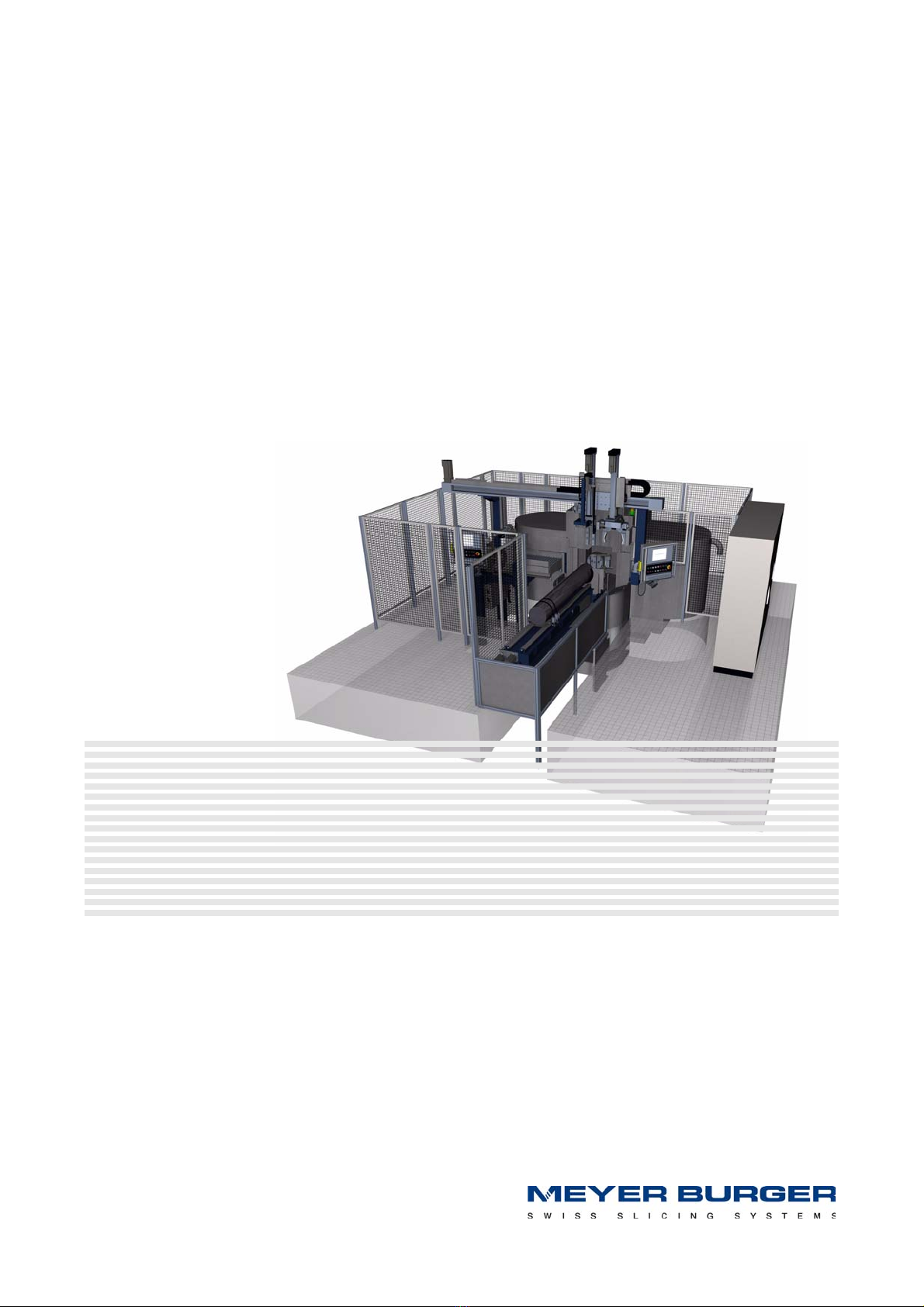
Band Saw BS 820
Manual


310002683-en-00
i
Table of Contents
1 Using the operating instructions ................................................................7
1.1 General .....................................................................................................7
1.2 Target group .............................................................................................8
1.3 Assessing the operating manual ................................................................8
2 Product description ...................................................................................9
2.1 Assemblies................................................................................................9
2.1.1 Machine ..................................................................................................10
2.1.1.1 Description..............................................................................................10
2.1.1.2 Machine assembly function .....................................................................12
2.1.2 Handling..................................................................................................13
2.1.2.1 Handling assembly function.....................................................................13
2.1.3 Crystal Gluing Station ..............................................................................14
2.1.3.1 Crystal gluing station assembly function ..................................................14
3 Safety......................................................................................................15
3.1 Safety information....................................................................................15
3.2 Intended use ...........................................................................................16
3.3 Dangers to life and limb and material values ............................................16
3.4 Faultless state of the machine .................................................................17
3.5 Organisational measures .........................................................................17
3.5.1 Safe and danger-conscious working .......................................................17
3.5.2 Safety and danger notes on the machine.................................................17
3.5.3 Changes to the machine .........................................................................17
3.5.4 Initial operation ........................................................................................17
3.5.5 Setup ......................................................................................................18
3.5.6 Maintenance and inspection....................................................................18

410002683-en-00BS 820 - Table of Contents
3.5.7 Decommissioning....................................................................................18
3.6 Personnel selection and qualification; principal duties ..............................18
3.6.1 Training ...................................................................................................18
3.6.2 Working on electrical equipment..............................................................18
3.7 Product specific hazards .........................................................................19
3.7.1 Saw band................................................................................................19
3.7.2 Control cabinet........................................................................................19
3.8 Safety installations Protection of personnel machinery .............................19
3.8.1 Cover ......................................................................................................20
3.8.2 Sliding door.............................................................................................21
3.8.3 Coolant monitoring..................................................................................22
3.8.4 Band drive speed monitoring...................................................................22
3.8.5 Standstill monitoring ................................................................................23
3.8.6 Safety clutch ...........................................................................................23
3.8.7 Band break monitoring ............................................................................23
3.8.8 Emergency stop ......................................................................................23
3.8.9 Coolant monitoring and adjustment.........................................................24
3.8.10 Motor cooling system ..............................................................................24
4 Product data ...........................................................................................25
4.1 Features ..................................................................................................25
4.2 Dimensions and weights..........................................................................27
4.3 Layout.....................................................................................................28
4.4 Connections............................................................................................29
4.4.1 Electrical connections..............................................................................29
4.4.2 Compressed air.......................................................................................29
4.4.3 Coolant supply ........................................................................................29
4.4.4 Coolant recirculation (waste)....................................................................29
4.4.5 Motor cooling system ..............................................................................30
4.4.6 Air exhaust ..............................................................................................30
4.4.7 Location of the various connections ........................................................30
4.4.8 Colour coding of the pipes ......................................................................31
4.5 Surroundings...........................................................................................31
4.5.1 Temperature of machine surroundings ....................................................31
4.5.2 Humidity of the machine surroundings.....................................................31
4.5.3 Location ..................................................................................................31
4.6 Emissions................................................................................................32
4.6.1 Noise levels .............................................................................................32
4.6.2 Used water..............................................................................................32
5 Display and operating controls ................................................................33
5.1 Operating panel.......................................................................................33
5.2 Signal column..........................................................................................34
5.3 Screen layout ..........................................................................................35
5.3.1 S keys .....................................................................................................35
5.3.2 F keys / Register .....................................................................................36
5.3.3 Toolbar....................................................................................................36
5.3.4 Password levels (PWL) ............................................................................38
5.3.5 Colours: Keys and displays of values.......................................................38
5.4 Confirmation switch.................................................................................39
5.4.1 Confirmation key .....................................................................................39
5.4.2 LED.........................................................................................................39
5.5 Hardware buttons ...................................................................................40
5.5.1 Beschreibung der Hardware-Tasten ........................................................41
5.6 Operation dressing device .......................................................................42
5.7 Starting and working with the application ................................................43
5.7.1 Login.......................................................................................................43
5.7.2 Configuration menu .................................................................................44
5.8 Loading, storing and deleting data...........................................................45
5.8.1 General ...................................................................................................45

10002683-en-00 5
5.8.2 “Storing data” action ...............................................................................46
5.8.3 “Loading data” action ..............................................................................47
5.8.4 “Deleting data” action..............................................................................47
6 Switching the machine on and off............................................................49
6.1 Switching on the machine and control system.........................................49
6.2 Switching off the machine and control system.........................................50
7 Setup ......................................................................................................51
7.1 Replacing the saw band ..........................................................................52
7.1.1 Removing the saw band..........................................................................52
7.1.2 Installing the saw band ............................................................................53
7.1.3 Tensioning the saw band.........................................................................53
7.1.4 Checking the axial running.......................................................................54
7.1.5 Switching off the band drive ....................................................................55
7.1.6 Adjusting the band guide to the saw band dimensions ............................55
7.1.7 Cooling nozzles .......................................................................................57
7.1.7.1 Adjusting coolant flow .............................................................................58
7.2 Dressing device.......................................................................................59
8 Cutting ....................................................................................................61
8.1 Cycle start...............................................................................................61
8.1.1 Preparing to start the cycle......................................................................61
8.1.2 Cancelling automatic mode .....................................................................62
8.1.3 Aborting the cycle ...................................................................................62
8.2 Moving away from the limit switch ...........................................................62
8.3 Engaging the safety clutch.......................................................................63
9 Maintenance............................................................................................65
9.1 Maintenance schedule.............................................................................65
9.2 Lubricant.................................................................................................66
9.3 Cleaning agent ........................................................................................66
9.4 Lubricating, care and cleaning work ........................................................67
9.4.1 Automatic central lubrication ...................................................................67
9.4.1.1 Topping up the lubricant tank..................................................................67
9.4.2 Threaded spindles of fall adjustment........................................................68
9.4.3 Hydraulic aggregate ................................................................................68
9.5 Inspection, checking and adjusting work .................................................69
9.5.1 Air maintenance unit................................................................................69
9.5.2 Buffer battery ..........................................................................................70
9.5.3 Ground clearance....................................................................................70
9.5.4 Brake ......................................................................................................71
9.5.4.1 Adjusting the brake switch.......................................................................71
9.5.5 Replacing the wheel ................................................................................72
9.5.5.1 Removing the wheel ................................................................................73
9.5.5.2 Fitting the wheel ......................................................................................73
10 Packing and transport .............................................................................75
10.1 Packing ...................................................................................................75
10.2 Transport ................................................................................................76
10.2.1 Notes ......................................................................................................76
10.2.2 Transport fixtures ....................................................................................77
10.2.3 Transport fixtures ....................................................................................77
11 Setting up and commissioning the machine.............................................79
11.1 Installation site / ambient conditions ........................................................79

610002683-en-00BS 820 - Table of Contents
11.1.1 Temperature............................................................................................79
11.1.2 Humidity..................................................................................................79
11.1.3 Location ..................................................................................................80
11.2 Unpacking the machine...........................................................................80
11.3 Transport fixtures ....................................................................................80
11.4 Aligning the Machine ...............................................................................81
11.5 Initial operation ........................................................................................82
11.5.1 Measures to be taken before initial operation...........................................82
11.5.2 Requirements on personnel doing the work.............................................82
12 Repair / Service.......................................................................................83
12.1 Service concept ......................................................................................83
12.2 Resources and material...........................................................................83
12.2.1 Special tools, measuring and testing instruments ....................................83
12.3 Fault finding and trouble-shooting............................................................84
12.4 Repair .....................................................................................................84
12.5 Equipment lists and diagrams..................................................................84
12.5.1 Arranged according to technical area ......................................................84
12.5.2 Numbering in equipment lists and diagrams ............................................84
12.6 Ordering spare parts ...............................................................................85
12.6.1 MB part numbers and manufacturers’ equipment designation.................85
12.7 Fault reporting procedure ........................................................................85
13 Putting out of service, storage and disposal ............................................87
13.1 Putting out of service...............................................................................87
13.1.1 Decommissioning....................................................................................87
13.1.2 Cleaning..................................................................................................87
13.1.3 Preservation ............................................................................................88
13.1.4 Fitting transport fixtures ...........................................................................88
13.1.5 Packing ...................................................................................................88
13.2 Storage conditions ..................................................................................88
13.2.1 Space required........................................................................................88
13.2.2 Danger note ............................................................................................88
13.2.3 Storage of spare parts.............................................................................89
13.2.3.1 Long-term storage of satellite roller spindles............................................89
13.3 Disposal ..................................................................................................89
13.3.1 Disposal measures ..................................................................................89

10002683-en-00 7
1
1. Using the operating instructions
1.1 General
This operating manual (OM) introduces the Band Saw BS 820 and explains
how to use it properly. The document takes you, as the reader, through the life cycles
of the machine and shows you, among other things, how the machine can be operated
and serviced safely and economically.
In contrast to drawings and details in this OM, the company reserves the right to make
technical modifications that are necessary to improve the machine or the assembly.
The “Meyer Burger AG” company name is abbreviated in this document to “MB”.
Note: In addition – this OM must be kept at the machine’s installed site at all times.

810002683-en-00BS 820 - Using the operating instructions
1.2 Target group
The OM must be read, understood and all points complied with by all persons
who are tasked with the following work with or on the machine:
■Operation including preparation, trouble-shooting during the working sequence,
removal of production waste, care, disposal of process materials
■Servicing (maintenance, inspection, repair)
■Transport
1.3 Assessing the operating manual
When drafting this OM, we carefully applied standards DIN 62079 (VDE0039)
and EN ISO 12100-2. Despite our efforts, experience tells us that an OM is not a static do-
cument – it is a living document and is experienced by others.
Please let us know of any suggestions for improvements to or comments about this OM!
Every contribution is welcome and will be reviewed by us.
Thank you in advance for your contributions.
Your technical editorial team

10002683-en-00 9
2
2. Product description
2.1 Assemblies
The BS 820 consists of the following assemblies:
■Machine
■Handling
■Crystal Gluing Station
These assemblies and their function are presented below in brief.

10 10002683-en-00BS 820 - Product description
2.1.1 Machine
Fig. 2-1 Machine
Legend 1 Clamping side wheel
2 Drive side wheel
3 Fall adjustment
4 Operating panel
5 Suction head
6 Band tensioning unit
7 Crystal infeed
8Sawband
9 Band drive
10 Cutting feed
11 Machine stand
2.1.1.1 Description
Machine stand Machine stand as a welded construction with high mechanical thermal stability.
Band tensioning unit Band tensioning unit with linear guide and two symmetrically arranged hydraulic cylinders.
Bearing unit Bearing unit with vertical axis and precision roller bearing to receive the wheels.
Wheel Wheel with centring flange for good concentric running and axial eccentricity
Band drive Band drive provided by AC motor (water cooled) with high torque and
optimum acceleration and deceleration properties.
Fall adjustment Fall adjustment for both wheels with precise and stable adjustment.
Band guide Band guide as an adjustable unit for the saw band and workpiece size
with high mechanical stability.
1
23
4
5
6
7
8
3
9
10
11

10002683-en-00 11
Cutting feed Cutting feed from bottom to top. Cutting feed movement provided by hydraulic cylinders
with electro-hydraulic control (with weighing cell to determine the cutting force).
Workpiece infeed Infeed for ingots and wafers
Dressing device Dressing device for the automatic dressing of the saw band by making incisions
in the dressing stone.
Electrical control Siemens PLC control system.
Modules for drive and positioning of the cutting feed, infeed and dressing axis.
Frequency converter for saw band and fall adjustment drive.
Monitoring, display and safety elements.
Hydraulic unit Hydraulic unit as a compact device for the following functions:
■Band tensioning
■Cover drive
■Cutting feed
■Workpiece supports and terminals
■Workpiece holder gripper

12 10002683-en-00BS 820 - Product description
2.1.1.2 Machine assembly function
Fig. 2-2 Operating principle
Legend 1 Crystal infeed
2 Workpiece
3 Wheel
4 Dressing stone
5Sawband
Axes
U / W Dressing
X Infeed (X1, X2, X3)
Z Cutting feed
The saw band Fig. 2-2/5 is fed horizontally over two wheels Fig. 2-2/3 and routed along
both sides of the workpiece Fig. 2-2/2 by guide jaws.
The band tensioning unit provides the appropriate tensioning force required by the saw
band. The cutting feed executes the cutting movement from the bottom upwards.
The saw band Fig. 2-2/5 is dressed with the dressing device Fig. 2-2/4.
It is positioned for dressing parallel to the infeed axis.
+x
-x
-z
+z
-u +u
12343
5
+w
-w
+x2
-x1
10002683-en-00 13
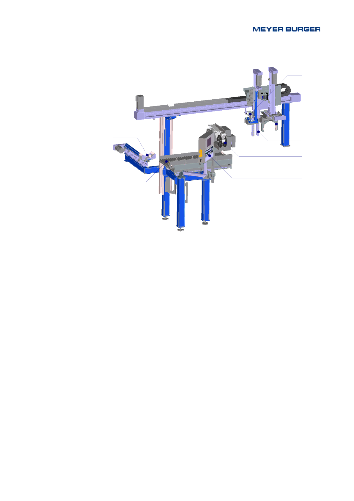
2.1.2 Handling
Fig. 2-3 Handling
Legend 1 Wafer thickness measuring device
2 Ingot removal
3 Wafer removal
4 Identification device
5 Operating panel
6 Wafer holding device
7 Rod and end piece holder
2.1.2.1 Handling assembly function
Handling is done automatically.
The following work steps are carried out:
■Removing ingots or wafers
■Dimensioning wafers
■Sticking on code labels
■Taking away ingots or wafers
1
2
3
4
5
6
7
14 10002683-en-00BS 820 - Product description
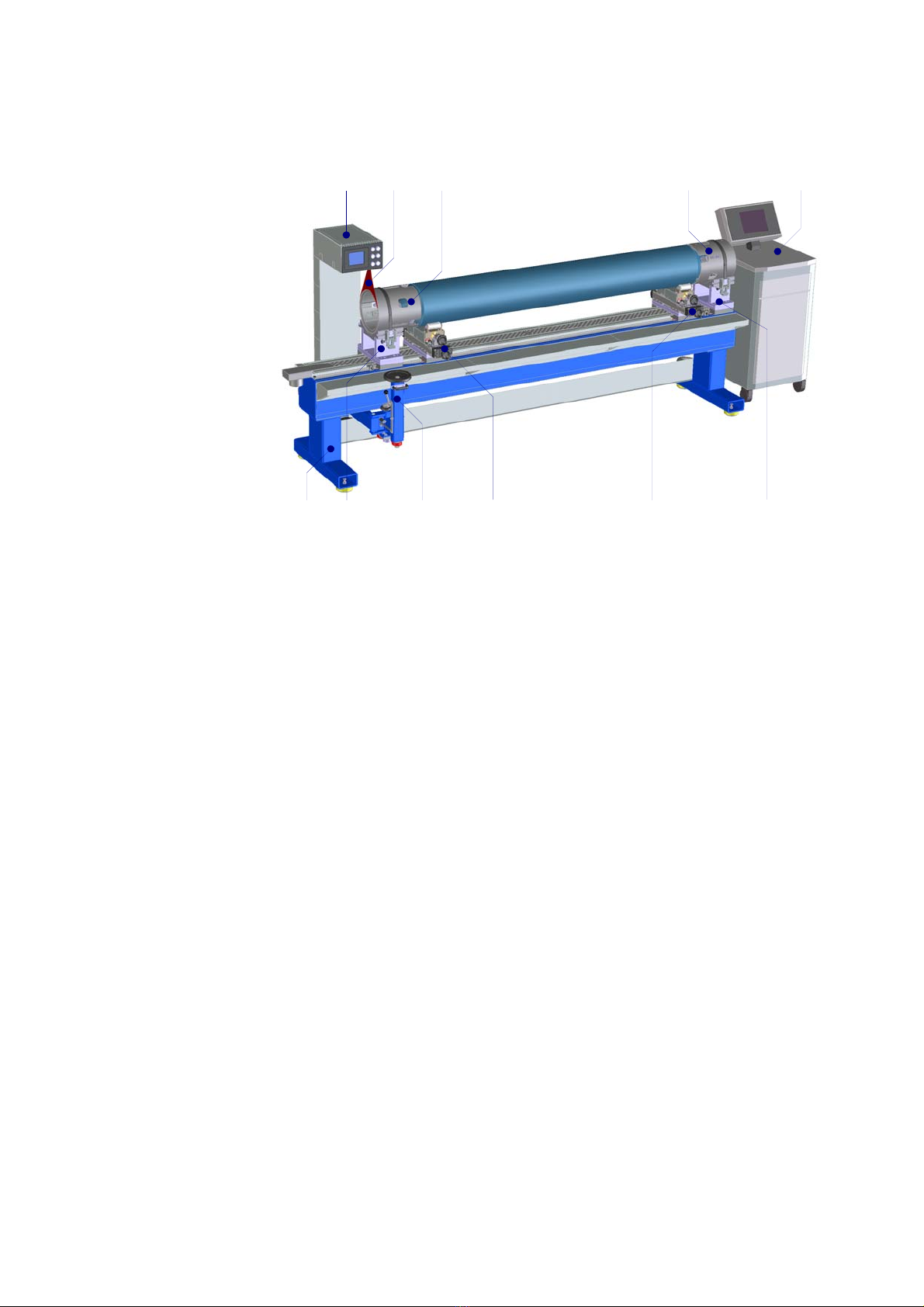
2.1.3 Crystal Gluing Station
Fig. 2-4 Crystal Gluing Station
Legend 1 Measuring arm operating panel
2 Laser light
3 Workstation
4Stand
5 Support
6 End piece holders
7 Adjusting unit
8 Measuring arm adjustment
2.1.3.1 Crystal gluing station assembly function
The crystals to be processed are measured on the crystal gluing station and
the cutting positions set.
The data are stored on the crystal gluing station’s PC and can be called up
by the band saw operators.
12366
45 877
5
10002683-en-00 15
3
3. Safety
Comply with national and in-house regulations on accident prevention and
on environmental protection.
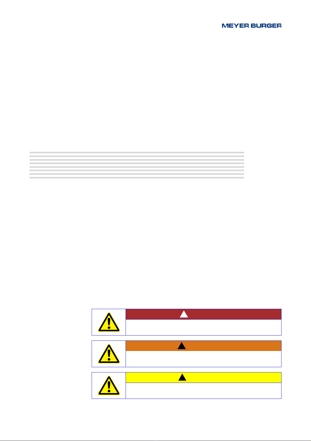
3.1 Safety information
In the operating manual, the following designations or symbols are
for especially important information:
DANGER
For a directly threatening hazard that can cause
severe personal injuries or death.
WARNING
For a hazard that may be directly threatening and that could cause
severe physical injuries or death.
CAUTION
For a situation that may possibly be dangerous and
that could cause slight physical injuries and material damages.
!
!
!

16 10002683-en-00BS 820 - Safety
3.2 Intended use
The Band Saw BS 820 is designed for the automatic slicing of long rods
of hard and brittle materials, mainly semiconductor material.
The special holding equipment for holding the rod in the machine allows the material
to be sliced up into
■ingots (sections)
■wafers
■end pieces
Minimum kerf loss, high accuracy and surface quality are achieved using procedures
with the band saw (diamond tool).
The machine can be operated only in a closed air conditioned room which all staff and
all visitors are entitled to visit only when wearing working clothing and safety shoes.
Any use different from or exceeding this is not regarded as intended use.
The manufacturer/supplier is not responsible for any damage arising from this.
The user alone is responsible.
The intended use of the machine at its installed site also includes following
the operating manual and complying with the inspection and maintenance conditions.
3.3 Dangers to life and limb and material values
The machine has been built according to the state of the art and the recognised
safety regulations. Nevertheless, dangers to life and limb of the user or third parties or im-
pairments to the machine and other material values may occur when using the machine.
NOTICE
This signal word is used as a warning of material damage.
Wear eye protectors
Warning about hand injuries caused by movement of the saw band
Warning of dangerous electrical voltage

10002683-en-00 17
3.4 Faultless state of the machine
Use the machine only in a technically faultless state and only for its intended use,
be aware of the safety regulations and dangers and follow the operating manual!
Clear (or have cleared) any faults, especially those that may impair safety, immediately!
3.5 Organisational measures
3.5.1 Safe and danger-conscious working
The personnel tasked with working on the machine must be familiar
with the operating manual before starting work. This applies especially to personnel
who work only occasionally on the machine, e.g. for preparation or maintenance.
Note: Personnel must not have open long hair, or wear loose clothing or jewellery
including rings.
There is a risk of injury, e.g. by getting caught in or drawn into the machine.
3.5.2 Safety and danger notes on the machine
Follow all safety and danger notes on the machine!
Keep all safety and danger notes at/on the machine complete and in a legible condition!
3.5.3 Changes to the machine
3.5.4 Initial operation
The initial operation of the machine may only be carried out by personnel authorised and
fully trained by MB or by an MB service engineer.
WARNING
In the event of safety-related changes to the machine or
its operating behaviour, shut down the machine immediately and
report the fault to the responsible office/person!
Do not make any changes, additions or alterations to the machine
that can impair safety!
This also applies to the installation and the adjustment of safety
equipment and valves and to welding at all load-bearing parts.
Spare parts must meet the technical requirements specified by
the manufacturer. This is always ensured with original spare parts.
Do not make any program changes (software) to the programmable
control system!
!

18 10002683-en-00BS 820 - Safety
3.5.5 Setup
The setup work may be done only by personnel authorised and fully trained by MB or
by an MB service engineer.
3.5.6 Maintenance and inspection
The maintenance personnel must be specially trained for the wider field of responsibility.
Note: Stipulated deadlines, or those given in the operating manual,
for recurrent checks/inspections are to be complied with!
Workshop equipment appropriate to the task is absolutely necessary for carrying out
the maintenance work.
Note: MB cannot be held liable for possible consequences or damage to individuals and
machines if the safety regulations are not complied with.
Note: Only the maintenance personnel has access to the main switch padlock.
3.5.7 Decommissioning
Decommissioning of machines can only be done by personnel authorised and fully trained
by MB or by an MB service engineer.
3.6 Personnel selection and qualification; principal duties
3.6.1 Training
Only trained or instructed personnel is to be employed.
It is the responsibility of the user or the operator to ensure that tasked personnel is trained
and instructed in accordance with the requirements.
We offer internal and external courses tailored to your needs for your safety.
3.6.2 Working on electrical equipment
Work on the machine’s electrical equipment may be carried out only
by a trained electrician or by persons instructed to work under the guidance and supervi-
sion of a trained electrician in accordance with the electrical regulations.
10002683-en-00 19
3.7 Product specific hazards
3.7.1 Saw band
■Operation at reduced speed is possible with the sliding door open.
3.7.2 Control cabinet
3.8 Safety installations Protection of personnel machinery
The machine has been built in accordance with the valid, state of the art conditions in terms
of protection of personnel.
During special operation (key-operated switch Fig. 5-4/11 in position “I” and confirmation
button pressed) the axes can be moved with the doors open.
CAUTION
Operation at reduced speed is possible with cover open.
Movement of the saw band!
Hand injury possible!
Work carefully with the cover open!
Wear protective goggles!
Keep third parties at a distance!
!
DANGER
Risk of electric shock!
Maintenance work cannot be carried out on electrical devices
with the main switch turned on!
When the main switch is turned off, the power supply
to the main switch remains live!
Electrical maintenance and service work may be carried out
only by trained specialist personnel in accordance
with national regulations.
!
CAUTION
The key for the switch in Fig. 5-4/11may be accessed only
by authorised personnel who can accept responsibility
for personnel safety.
Personnel may not leave the machine if the key is at position “I”
and inserted.
!
20 10002683-en-00BS 820 - Safety
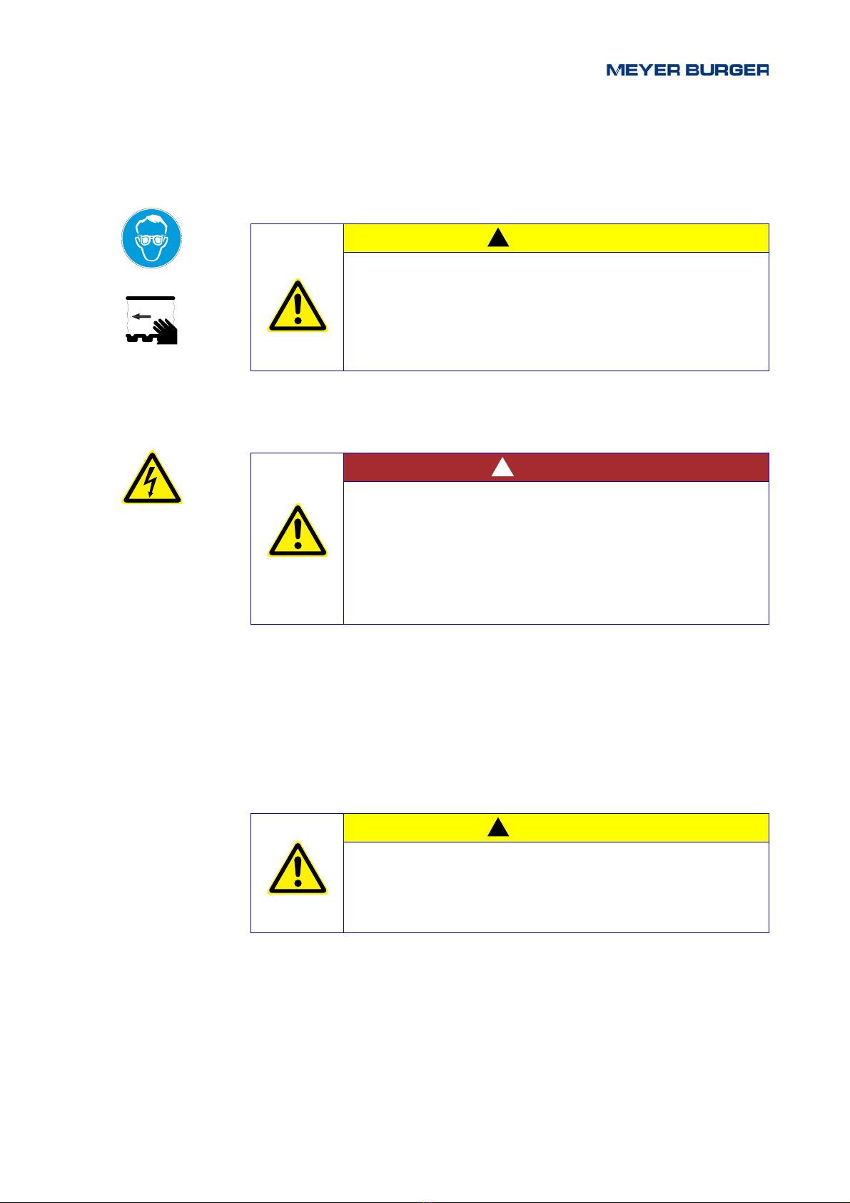
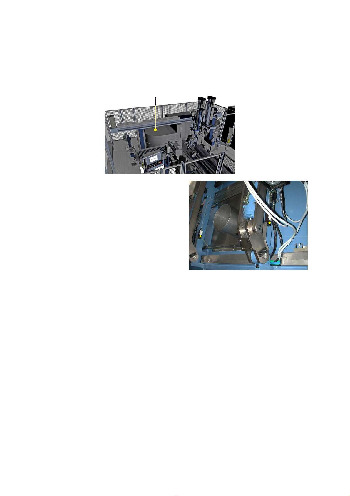
3.8.1 Cover
Safety switches Fig. 3-1/2 and Fig. 3-13 monitor the position of the cover.
The automatic mode cannot be started until the cover is closed and locked.
Fig. 3-1 Cover safety switch
Legend 1 Cover
2 Drive side safety switch
3 Clamping side safety switch
1
2
3
Table of contents
Popular Saw manuals by other brands

Scheppach
Scheppach 5905109901 Translation from the original instruction manual

Jet
Jet HVBS-56M Operating instructions and parts manual

Bosch
Bosch GCM 10 MX Professional Original instructions

KRESS
KRESS KU420 Safety and operating manual

Clarke
Clarke Contractor CTS12 operating & maintenance manual

Metabo
Metabo SSE 1100 Original instructions


