Meyer Sound RMS 4.5 User manual

USER GUIDE
RMS™4.5

ii
© 2004 Meyer Sound. All rights reserved.
RMS™ 4.5 Remote Monitoring System User Guide
The contents of this manual are furnished for informational purposes only, are subject to change without notice, and should not be construed as a
commitment by Meyer Sound Laboratories Inc. Meyer Sound assumes no responsibility or liability for any errors or inaccuracies that may appear
in this manual. Except as permitted by applicable copyright law, no part of this publication may be reproduced, stored in a retrieval system, or
transmitted, in any form or by any means, electronic, mechanical, recording or otherwise, without prior written permission from Meyer Sound.
Intelligent AC, RMS and REM are trademarks of Meyer Sound. Meyer Sound, Meyer Sound MAPP Online, SIM, TruPower and QuickFly are
registered trademarks of Meyer Sound Laboratories Inc. (Reg. U.S. Pat. & Tm. Off.). All third-party trademarks mentioned herein are the property
of their respective trademark holders.
Excerpts from the i.LON® 10 Ethernet Adapter User's Guide documentation reprinted with permission of Echelon.
Excerpts from the i.LON® 10 Ethernet Adapter Quick Start Guide documentation reprinted with permission of Echelon.
Except as expressly permitted, no part of this publication may be reproduced, stored in a retrieval system, or transmitted, in any form or by any
means, electronic, mechanical, photocopying, recording, or otherwise, without the prior permission of Meyer Sound Laboratories, Inc. Excerpts
from the i.LON 10 Ethernet Adapter Quick Start Guide documentation may not be reproduced, stored or transmitted without the prior permission
of Echelon Corporation.
Printed in the U.S.A.
Part Number: 05.033.302.02 A

iii
CONTENTS
INTRODUCTION 1
How to Use this Guide 1
Introducing the RMS™ Remote Monitoring System 1
User Interface 1
Network Hardware 1
How this Guide Is Organized 2
CHAPTER 1: Planning and Designing for RMS 3
System Requirements 3
Hardware Components 3
The RMS User Panel 3
Network Connectors 3
Service LED (Red) 3
Wink LED 4
Activity LED 4
Service Button 4
Reset Button 4
Desktop PCI Network Interface Card 4
Laptop PCMCIA Network Interface Card 4
i.LON 10 Ethernet Adapter I/O 4
FTR-120 Network Repeater 4
Network Terminator 5
Custom Twisted-Pair Connectors 5
Twisted pair vs. Ethernet 5
Twisted pair 6
Ethernet 7
Understanding the i.LON 10 9
Hubs and Switches 9
Network Specifications 10
Maximum Loudspeaker Nodes 10
Twisted-Pair Cable Type 10
Ethernet Cable Type 10
Connector Types 10
Maximum Network length 10
Termination 10
Connector Type 10
Network Platform 10
Transceiver 10
Data Rate 10
RMS Network Design Examples 11
CHAPTER 2: Installing Transition Hardware 15
Installing an RMS Network Communication Module (MP or HP Amplifier) 15
Installing or Upgrading an RMS Network Communication Module (UltraSeries) 19
Copper Strip 20
Locking Connector 20
Mute-Enable Jumper Installation 21
Installation of the RMS Connector Assembly 21
Termination Installation 21
Installation and Operation of the FTR-120 Network Repeater 22
Mechanical Installation 22
Network Terminations 22
Wiring 23
Universal Power Supply 23
FTR-120 Specifications 23

iv
CHAPTER 3: Installing Software and Network Adapters 25
Backing Up and Importing the RMS Database 25
Backing Up your RMS Database and Panel Files 25
Removing and Importing a Network Database 26
Removing a Network Database 26
Importing a Network Database 27
Installation and Setup 28
Launching RMS Setup 28
Validating the Network Interface Card (Not necessary for i.LON only users) 29
Running RMS for the First Time 31
Connecting and Configuring the i.LON 10 Ethernet Adapter 32
Connecting the i.LON 10 32
Configuring the i.LON 10 32
Configuring the LonWorks Interface 35
Initializing the i.LON 10 into the RMS Database 36
CHAPTER 4: Using RMS Software 37
Using the RMS Application 37
The Panel 37
Working with Pages 37
Adding a Page 37
Deleting a Page 38
Renaming a Page 38
Adding and Commissioning a Loudspeaker 38
Understanding Device Credits 40
Commissioning Loudspeakers Using the Neuron ID Number 41
Speeding Up the Process 42
Device Names Used on this Panel 42
Device Names in the Network Database 42
Deleting a Loudspeaker 43
Loudspeaker Views 43
Icon View and Small Icon View 43
Text View 45
Working with Views 46
The Properties Menu 46
Control Functions 47
Mute 47
Wink 47
Solo 47
Solo/Mute Matrix Controller 47
The Options Menu 50
Status Bar 50
Background 50
Network Setup 50
Title 50
UX Attenuation Range 50
APPENDIX A: RMS Application Command Key Reference 51
APPENDIX B: Advanced i.Lon 10 Configuration 53
RMS CONFIGURATION DATA SHEET 57

1
INTRODUCTION
HOW TO USE THIS GUIDE
As you read this guide, you’ll find figures and diagrams to
help you understand and visualize what you’re reading.
You’ll also find numerous icons that flag important infor-
mation or warn you against improper or potentially harmful
activities. These icons include:
A NOTE identifies an important or useful
piece of information relating to the topic
under discussion.
A TIP offers a helpful tip relevant to the
topic at hand.
A CAUTION gives notice that an action
can have serious consequences and could
cause harm to equipment or personnel, delays, or
other problems.
INTRODUCING THE RMS™ REMOTE
MONITORING SYSTEM
The RMS remote monitoring system was developed by
Meyer Sound to monitor the electronic operating param-
eters of Meyer Sound self-powered loudspeakers during
operation. RMS employs an Echelon® LonWorks® net-
work to monitor system performance in a client software
application running on a Windows® PC, creating a new
level of loudspeaker and amplifier diagnostic interaction.
RMS allows you to remotely perform such monitoring
tasks as:
■ Verifying operation status upon system setup
■ Verifying loudspeaker polarity
■ Controlling Mute and Solo functions
■ Protecting loudspeakers by monitoring limiting activity
■ Detecting failed components
RMS also monitors many loudspeaker and amplifier pa-
rameters, including:
■ Amplifier channel output voltage (peak and average)
■ Amplifier channel output power
■ Limiting and excursion
■ Input voltage
■ Amplifier temperature and fan speed
■ Polarity
USER INTERFACE
The RMS application uses different “views” – icons, me-
ters, and text – to display the data you need about your
system depending on your preferences. Views contain
loudspeaker identification information and data from the
amplifier, controller, driver, and power supply of the loud-
speakers in your network; system status conditions cause
color changes in icon and meter indicators to alert you of
faults, excessive levels, and other critical data.
Views are moveable, and typically are arranged on the
screen to reflect the physical layout of the loudspeakers.
You can design a screen full of icons, meters and text,
then save it to a file, giving you the ability to create differ-
ent layouts according to the needs of the system design.
In addition, Mute and Solo control functions are available
and can be enabled/disabled in software or hardware.
NETWORK HARDWARE
Loudspeakers are identified on the network by node
names kept in the RMS database. RMS uses an estab-
lished network platform developed by Echelon Corpora-
tion, the world’s leading supplier of networking technology
for monitoring and control. The platform is not affected
by loss of power at a loudspeaker node, does not require
coaxial or fiber optic lines, is polarity insensitive, and sup-
ports Free Topology (flexible wiring configuration).
An RMS network is a real-time data acquisition system,
so no data is lost during transmission. A standard RMS
network allows up to 62 nodes (115 with a repeater) of
self-powered loudspeakers using a twisted-pair connec-
tion, and several hundred nodes using an Ethernet-based
setup.
INTRODUCTION

2
INTRODUCTION
HOW THIS GUIDE IS ORGANIZED
The RMS 4.5 User Guide is divided into four chapters plus
an appendix that contains useful keyboard shortcuts for
the RMS application. An RMS configuration data sheet, for
logging information about the loudspeakers on your RMS
network, is also included at the end of the guide.
The chapters are organized as follows:
■ Chapter 1, “Planning and Designing for RMS,” gets you
started by showing you how to plan your RMS network.
■ Chapter 2, “Installing Transition Hardware,” takes you
through the process of installing your hardware cor-
rectly.
■ Chapter 3, “Installing Software and Network Adapters,”
explains how to install RMS software components, and
walks you through configuring the i.Lon 10 Ethernet
Adapter.
■ Chapter 4, “Using RMS Software,” explains how to use
RMS software, from commissioning loudspeakers to
controlling Mute, Solo and Wink functions.
Information in this User Guide is applicable as of the date
of this printing. Updates and supplementary information are
posted on the Meyer Sound website at:
http://www.meyersound.com
Contact Meyer Sound Technical Support at:
Tel: +1 510 486.1166
Fax: +1 510 486.8356
Email: [email protected]
3
CHAPTER 1
This chapter will help you understand the issues involved
in planning an RMS network for your system design. Type
of hardware, number of loudspeakers and their layout are
all crucial to setting up a fast, trouble-free RMS network.
SYSTEM REQUIREMENTS
To ensure that the RMS monitoring system runs smoothly,
the following system specifications are required:
■ Windows® 98SE/NT 4.0 (SP5)/2000/XP™ (SP1) or
higher
■ Pentium® III processor or higher (350 MHz min., 500+
MHz recommended
■ 64 MB RAM min. for 98SE/NT, 128+ recommended;
128 MB RAM min. for 2000/XP, 256+ recommended
■ 4 MB video card or higher (800 x 600 min. resolution)
■ At least 50 MB free hard drive space.
■ For a large network: 20 MB/s sustained transfer rate
with less than 8 ms average seek time
■ One open full-size, 32-bit (standard) PCI slot or Type II
PC Card (PCMCIA) card slot
CAUTION: A half-size PCI slot will not
accommodate the Network Interface Card
used by RMS. Ensure that you have a full-sized,
standard PCI slot available.
NOTE: If you are running the RMS
application on a laptop computer, a
PCMCIA Type II port is required.
TIP: RMS is designed to multitask with
other Windows applications. However,
because of the large amount of data processing
and monitoring that must occur in real-time, Meyer
Sound recommends running RMS as a stand-alone
application (no other applications running). If you
experience problems running RMS in conjunction
with other Windows applications, close the other
programs to determine if the problem is due to a
conflict with those applications.
If you do decide to multitask RMS with other
applications, please be aware of the following:
■ Avoid operations that are CPU intensive. For
example, audio (signal) processing, spectrum/
frequency analyzers, large file copying, and
playing music and video files.
■ Avoid operations that are network intensive (i.e.
those that heavily use the Ethernet port). For
example, streaming audio/video, large network file
transfers, Web/Internet browsing of multimedia
content, and heavy use of email or instant
messaging.
HARDWARE COMPONENTS
RMS ships with a number of different hardware options
depending on how you decide to configure your
network. This section will walk you through the different
components for a twisted pair versus an Ethernet-based
network, as well as the components common to both
types of networks.
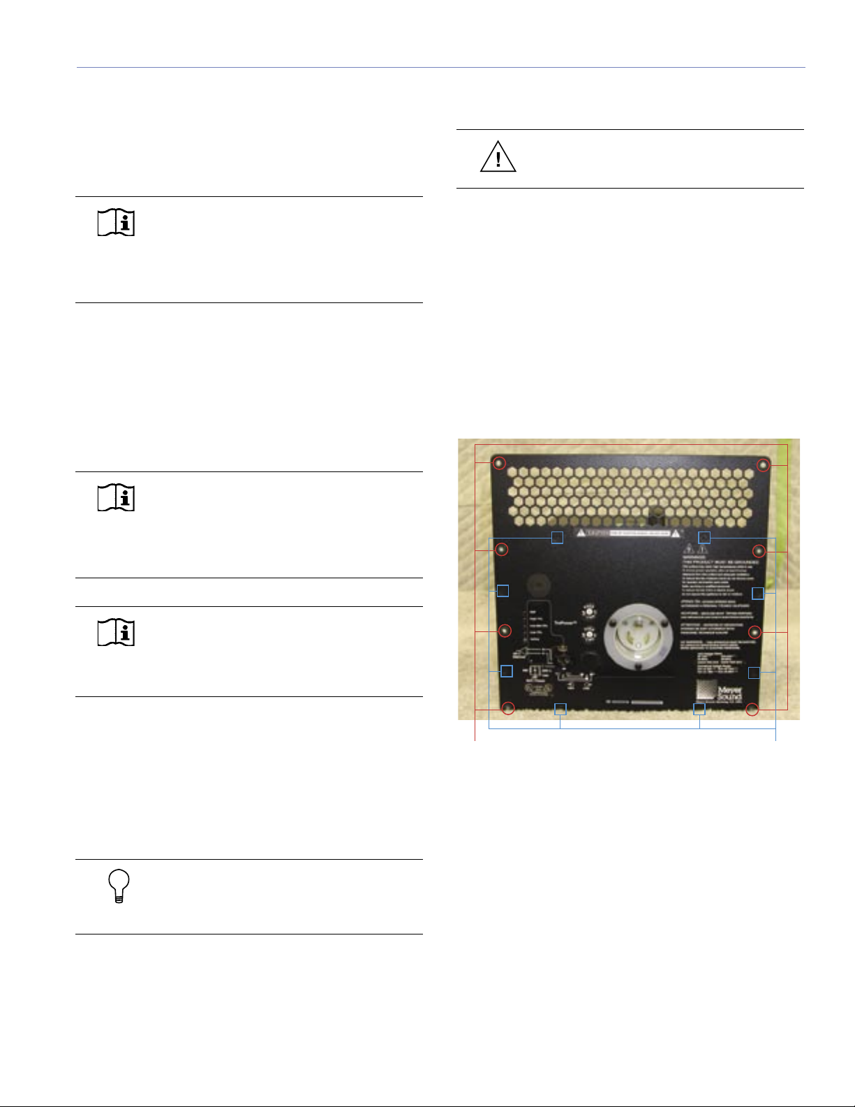
The RMS User Panel
You must have an interface on the loudspeaker before
you connect to it through a network. All Meyer Sound
self-powered loudspeakers (with the exception of the
HD-1/2, UPL-1/2 and HM-1S) can be equipped with an
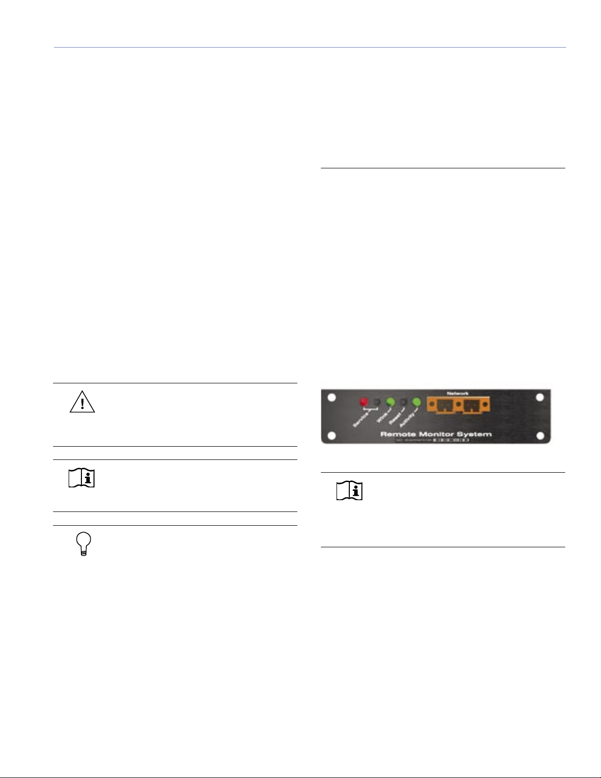
RMS communications module. The module's user panel is
shown in Figure 1.1.
Figure 1.1. The RMS communication module’s user panel
NOTE: All M Series loudspeakers are fitted
with the RMS communications module
as standard. The RMS communications module
is available as an option for other self-powered
Meyer Sound loudspeakers.
The user panel is straightforward, with three LEDs and two
buttons. Their functions are as follows:
Network Connectors
Two Weidmuller locking network connectors enable data
transmission to and from the network. The connectors are
bi-directional – able to both transmit and receive network
data.
Service LED (Red)
When blinking once every two seconds, the Service LED
indicates that the communications module is operational,
but the loudspeaker is not installed on the network. When
the loudspeaker has been installed on the network the
Service LED will be not be lit, while the Activity LED will
CHAPTER 1: PLANNING AND DESIGNING FOR RMS

4
CHAPTER 1
flash continuously. When continuously lit, the Service LED
indicates that the loudspeaker has a local RMS hardware
failure. In this case, the RMS communications module
may be damaged and you should contact Meyer Sound
Technical Support.
Wink LED
When the Wink LED is lit, it indicates that an identifying
signal has been sent from the host computer to the
loudspeaker. This is achieved using the service pin on the
loudspeaker and the RMS application.
NOTE: See Chapter 4 for more details on the
Wink function.
Activity LED
When the loudspeaker has been installed, the Activity
LED will flash continuously indicating that data is being
transmitted to the host computer. If not lit, the loudspeaker
has not yet been installed on the network.
Service Button
Pressing the service button will both commission and
identify a loudspeaker on the network. When pressed,
a happy face is displayed over the corresponding
loudspeaker’s icon in the RMS application.
NOTE: Chapter 4, “Using RMS Software”
covers the commissioning process in detail.
Reset Button
Pressing this button will reset the communications module
and reset the module’s control functions (e.g., causing
a muted loudspeaker to unmute or decommissioning a
loudspeaker from the network).
Desktop PCI Network Interface Card
If your RMS host computer is a desktop PC, you will
use an Echelon PCLTA-20 network card. The PCLTA-
20 card is a high-performance LonWorks PCI card for
desktop computers. Make sure that your computer can
accommodate a full-size, standard PCI card.
Laptop PCMCIA Network Interface Card
If you need the flexibility of a laptop for touring or portable
applications, you will need a PCC-10 network card. Make
sure that your laptop has a Type II PC card (formerly
PCMCIA) slot. This card supports the LonWorks®
interface and comes with an adapter cable to patch into
the network with a Weidmuller male connector.
i.LON 10 Ethernet Adapter I/O
The i.LON 10 Ethernet Adapter converts a twisted-pair
network to an Ethernet 10BaseT connection. This allows
you to connect your RMS network(s) to an RMS Host
computer via a standard Ethernet network. Multiple i.LON
10 Ethernet Adapters can be connected to a single RMS
Host to make up a larger RMS network with sub-networks
– highly useful for operating over long distances with a
large number of nodes.
The i.LON 10 uses standard 10BaseT cabling and an RJ-
45 connector.
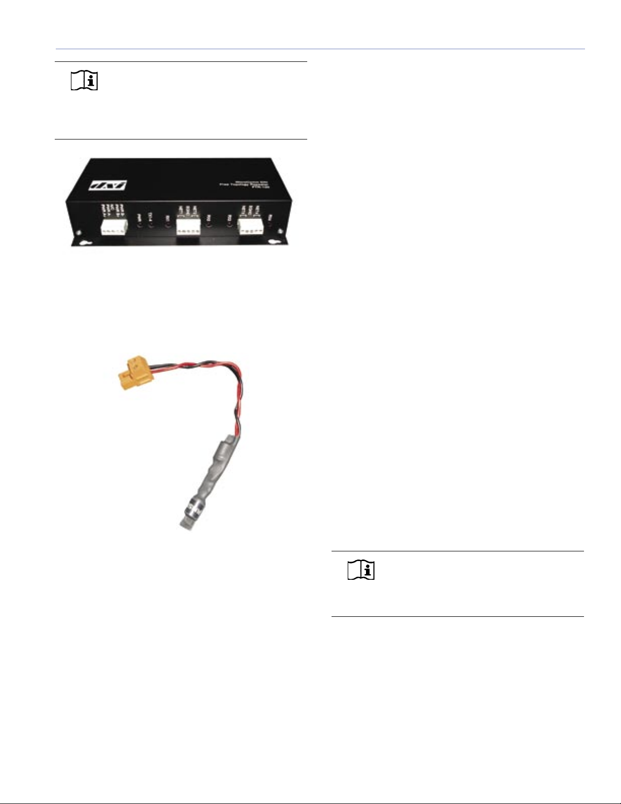
FTR-120 Network Repeater
The FTR-120 network repeater allows you to increase
the geographical coverage of your network. A network
repeater should be used in situations when an Ethernet-
based network is impractical – for example, when touring
with RMS and a simple twisted-pair network.
5
CHAPTER 1
NOTE: A repeater is a network device that
connects multiple segments of a network
cable. It re-times, strengthens, and regenerates the
incoming signal then sends the signal back to the
network.
Network Terminator
An RMS network terminator is a simple resistive capacitive
device designed to prevent electrical reflections on the
network. The terminator can be installed at almost any
location in the network depending on topology.
Custom Twisted-Pair Connectors
When designing twisted-pair cable runs, it’s not
uncommon to use a custom wall plate or connector to
make the connections more user-friendly. This is typical for
a theater or touring rig depending on design requirements.
TWISTED PAIR VS. ETHERNET
RMS is available in both twisted-pair and Ethernet
versions. When deciding which technology to use for your
RMS system, consider the following:
■ The number of loudspeakers on the network
■ The amount of cabling needed to run the network
■ Fixed or portable installation
■ The distance between your host computer and the
loudspeakers on the network
■ Existing Ethernet network access points at the venue
(if available)
A simple twisted-pair network, for example, works in most
situations. It’s easy to wire and requires no additional
networking routers, switches or hubs, although a repeater
is required for runs over 1,640 feet. A more cost-effective
solution (and a practical solution when a repeater is
required) for installations with an Ethernet infrastructure is
to run multiple i.LON-10 Ethernet adapters. Using i.LON-
10s also minimizes data traffic on larger networks, making
the RMS system more responsive.
More important, the network could be overloaded by
running long lengths of twisted-pair cabling on a subnet.
Overloading an RMS network is usually the result of the
following:
■ You are attempting to pass more data through the
network than what it is equipped to handle. More
than 50 loudspeakers on one network segment may
overload the network in this way.
■ The distance between the host computer and the
first loudspeaker (max-to-node) is greater than 1,640
feet (500 meters) in a non-repeater system, or the
length of one network segment (node-to-node) in a
system using a repeater is greater than 1,640 feet (500
meters).
NOTE: For best performance, it is
recommended that the distance between
the host computer and a loudspeaker not be more
than 1,450 feet (450 meters).
If you overload the network, the result is that the critical
data will reach you very slowly – or not at all. Like any
network, the software and hardware components in RMS
are interacting continuously to transmit information to the
host computer about the loudspeakers connected to the
network.
6
CHAPTER 1
Twisted Pair Network Cable
Twisted Pair Network Cable
Loudspeakers
RMS Work Station
RMS Host Software
LNS Server
RMS Database
Network Interface Driver (1-62)
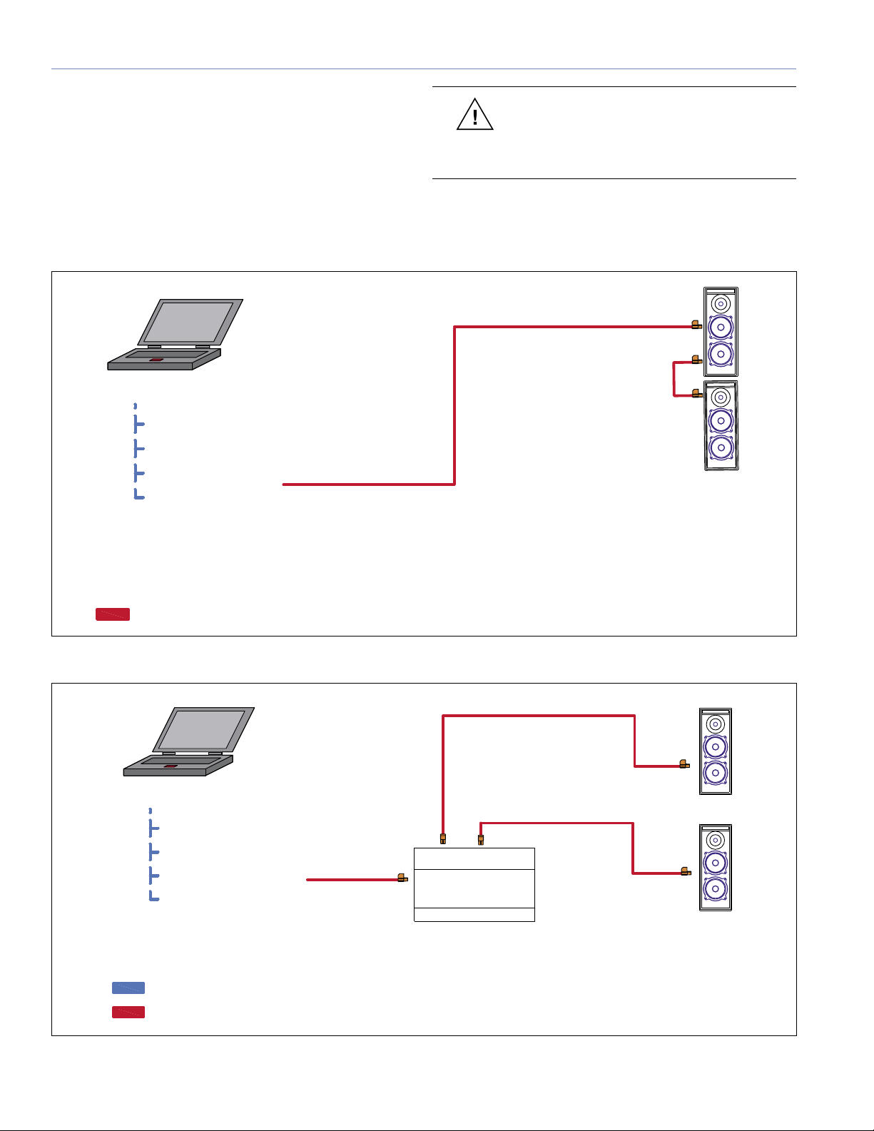
Figure 1.2. Simple twisted-pair network configuration
Twisted pair
Figures 1.2 and 1.3 show typical network configurations for
simple twisted-pair and twisted-pair repeater configurations.
When designing a twisted-pair RMS network, pay close
attention to the wiring, cable gauge, and connector
requirements (discussed in the section “Network
Specifications” later in this chapter) which are important to
good performance.
CAUTION: Consider using a repeater in
the network if you are within 1,640 feet
of exceeding the cable length or if you are using
VEAM™ connectors in your system design.
Ethernet Cat 5 Patch Cable
Twisted Pair Network Cable
RMS Work Station
RMS Host Software
LNS Server
RMS Database
Network Interface Driver
FTR-120 NETWORK
REPEATER
Loudspeakers
(1-62)
Loudspeakers
(1-62)
(1-115)
Quantity
Twisted Pair Network Cable
Twisted Pair Network Cable
Figure 1.3. Twisted-pair network configuration with repeater

7
CHAPTER 1
Laptop
Network Crossover Cable
Network Crossover Cabe
Twisted Pair Network Cable
i.Lon 10
Static IP Address
Loudspeakers
(1-50)
Twisted Pair Network Cable
RMS Workstation
Ethernet Cat 5 Patch Cable
Twisted Pair Network Cable
3Com
OFFICE
CONNEC T
PWR
Alert
Switch140
1234
PortStatus
12
3
4
Activity
10BASE-T
green= link OK yellow= Packet
Port
Status Activity
100BASE-TX
Network Switch
i.Lon 10
Static IP Address
i.Lon 10
Static IP Address
Ethernet Cat 5 Patch Cable
Loudspeakers
(1-50)
Loudspeakers
(1-50)
Twisted Pair Network Cable
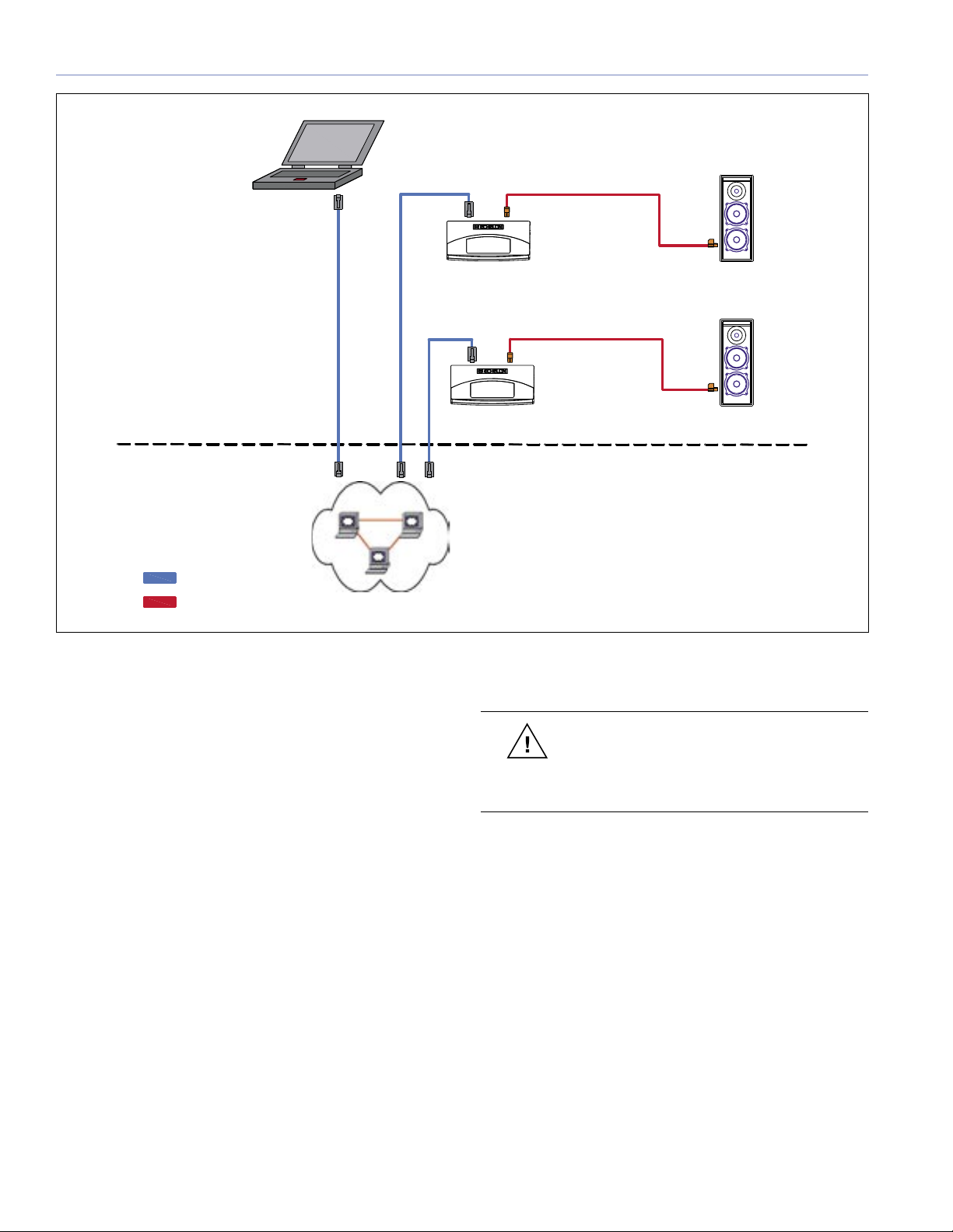
Figure 1.5. Closed Ethernet-based network configuration with multiple iLons
Figure 1.4. Simple closed Ethernet-based network configuration
Ethernet
Figures 1.4 through 1.6 on the following pages show
various network configurations for a simple Ethernet-based
network configuration.
NOTE: An Ethernet-based RMS system is
more complex from a design standpoint
and must conform to Ethernet network design
specifications (beyond the scope of this guide). A
general knowledge of Ethernet networks is very
helpful if you plan to deploy an Ethernet-based
system.
8
CHAPTER 1
The advantages of an Ethernet-based network are:
■ A larger number of loudspeakers may exist on a single
network
■ A wider area of available locations
■ Improved network speed
CAUTION: Meyer Sound recommends
that an Ethernet-based RMS network be
deployed as a closed, separate network to reduce
network problems from outside network traffic.
Figure 1.6. Ethernet-based network configuration using existing Intranet infrastructure
Loudspeakers
Ethernet Cat 5 Patch Cable
Twisted Pair Network Cable
Loudspeakers
Ethernet Cat 5 Patch Cable
Intranet
i.Lon 10
Static IP Address
i.Lon 10
Static IP Address
RMS Work Station
(1-50)
(1-50)
Twisted Pair Network Cable
Twisted Pair Network Cable

9
CHAPTER 1
Understanding the i.LON 10
As discussed earlier in this chapter, the i.LON 10 Ethernet
Adapter converts twisted-pair network data to Ethernet
network data, allowing you to connect RMS to one or more
LNS servers via the TCP/IP protocol.
Each i.LON 10 must have its own static IP address, which
will provide its RMS identity as a network segment in the
network database. It will also have its own database in the
RMS host computer and each network database segment
will contain all of the Neuron ID (the unique loudspeaker
identification number) information on the network for the
loudspeakers contained on that particular segment of the
network.
NOTE: i.LON 10 installation procedures
are covered in more detail in Chapter 2,
“Installing Transition Hardware.”
Hubs and Switches
A hub is a device that joins multiple computers or other
network devices together to form a single network segment.
Switches look nearly identical to hubs, but a switch is
more intelligent. Switches are capable of inspecting the
data packets as they are received, determining the source
and destination device of that packet and forwarding
that packet appropriately. Switches conserve network
bandwidth and offer better performance than hubs.
A Hub or a Switch is needed for an RMS Ethernet network
that contains more than one i.LON 10 or if you are sharing
an existing Ethernet network connection.
NOTE: A network repeater or an Ethernet-
based system with multiple i.LON 10s is
required if you want to connect more than 62
loudspeakers to an RMS host computer. This
will increase the data traffic capacity through the
network as well as signal strength over longer cable
runs.
TIP: While it is possible to wire an RMS
system in a near-infinite number of ways, a
typical network using Free Topology (flexible wiring
configuration) can only address 62 loudspeaker
nodes over a maximum cable length of 500 meters
(1,640 feet) using 20 AWG cable and a single
bus terminator (a terminator is a simple resistive
capacitive device designed to prevent network
reflections.).
NOTE: Each i.LON 10 equals one network
segment. You can have many network
segments within a network depending on your
installation needs.

10
CHAPTER 1
NETWORK SPECIFICATIONS
Maximum Loudspeaker Nodes
■ Twisted-pair system with a maximum of 62 nodes
(maximum of 50 recommended); up to 115 nodes with
a network repeater
■ Ethernet network with i.LON 10 with up to 50 nodes
per network segment
Twisted-Pair Cable Type
■ 20 AWG (Belden 8205 or equivalent) twisted pair,
stranded, unshielded
Ethernet Cable Type
■ Category 5 or higher. Straight-through (patch) cable
if using a hub or a switch. Use a crossover cable if
wiring the computer's Ethernet port directly to an
i.LON 10.
Connector Types
■ Twisted pair: Weidmuller 2 conductor locking
connector
■ Ethernet: 10BASE-T, type RJ-45
■ Portable: XLR and EN3
Maximum Network length
■ Maximum network length without installation of
repeater(s):
- Free Topology: 20 AWG, 18 AWG or 16 AWG
cable, one 52.3-ohm type terminator: 500 m (1,640
ft)
- Ethernet: 10BASE-T network limitations plus
Standard twisted pair limitations
Termination
■ Free Topology: One 52.3-ohm type terminator at any
point
■ Bus Topology: Two 52.3-ohm type terminators (one on
either end)
Connector Type
■ 2-wire plug with recommended snap-on lock
Network Platform
■ Differential Manchester Encoding; Polarity Insensitive,
Free Topology
Transceiver
■ EMI, complies with FCC Part 15, Class A; UL
recognized; VDE: EMI compliant
Data Rate
■ 200 ms data transfer rate with 20 loudspeakers

11
CHAPTER 1
RMS NETWORK DESIGN EXAMPLES
This section focuses on examples of several RMS system
designs that can serve as building block diagrams for an
RMS network. These examples show how the twisted-pair
and Ethernet connections are made to reduce network
load.
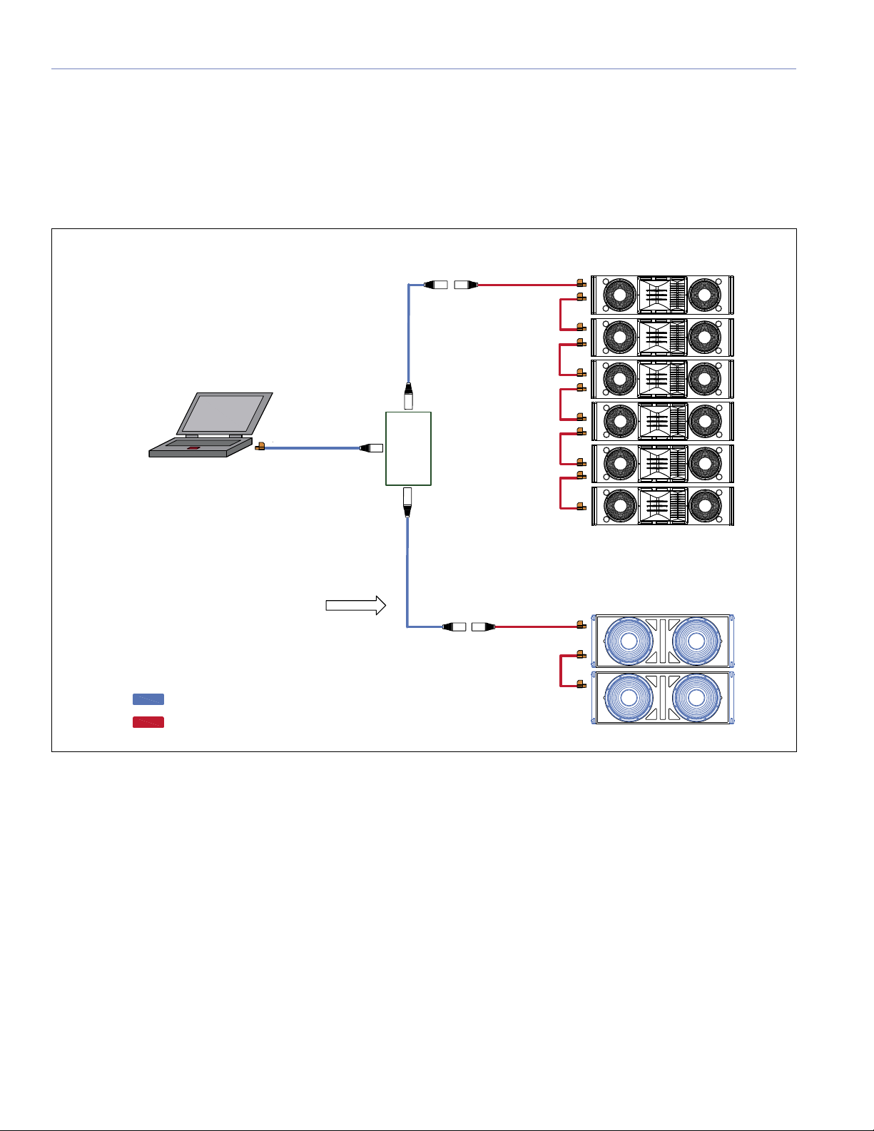
Small- to Mid-Sized Venue
If you’re planning for a small- to mid-sized venue, a
twisted-pair network is typical. Proper planning of the
cable runs to each loudspeaker and termination points
are important for reducing excess cable in the network
and minimizing network latency. You can also design
an Ethernet solution for a small- to mid-sized venue if
needed.
RMS work station
front-of-house or
a remote location
Twisted Pair Network Cable
User-supplied termination
panel provides parallel
termination in a close central
location to the loudspeakers
Twisted Pair Network Cable
RMS looping to next
cabinet in the array
12
CHAPTER 1
Touring or Portable Applications
Touring or portable applications may require a flexible
twisted-pair network. Using a laptop and keeping your
existing inventory of loudspeakers commissioned and
organized will make using RMS simple to setup and easy
to use.
RMS data can be connected to FOH through any "dry
pair" on an analog multi-pair snake system, and it’s helpful
to use a proprietary connector, such as a 4-pin XLR
connector, to avoid possible confusion with microphone or
line input signal paths.
RMS work station
front-of-house or
a remote location
Twisted Pair Network Cable
System Drive Line
RMS
Looping
Custom XLR or a custom
dedicated RMS connection
System Array
Mult Box
Parallel
2-Conductor Wire
RMS data can be connected to Front of House
through any “dry pair” on an analog multi-pair
snake system. Avoid possible confusion with
microphone or line input signal paths by clearly
labeling 3-pin XLR connectors – or use a
proprietary connector, such as a 4-pin XLR.
Twisted Pair
Network Cable
Twisted Pair
Network Cable
Custom XLR or a custom
dedicated RMS connection

13
CHAPTER 1
Large Venue Applications
For larger venues such as theatres, stadiums, arenas,
hotels, and theme parks, an Ethernet-based network, using
multiple i.LON 10s, is preferred for increased network speed
and durability.
When planning an Ethernet network you still have to convert
to twisted pair from the i.LON 10 to your loudspeaker
locations. Doing so allows you to form a hybrid network
between twisted-pair and Ethernet type cabling (10BASE-T).
RMS Work Station
Twisted Pair Network Cable
3Com
OFFICE
CONNEC T
PWR
Alert
Switch140
1234
Port Status
1234
Activity
10BASE-T
green= li nk OK yellow= P acket
Port
Status Activity
100BASE-TX
Network Switch
Ethernet Cat 5 Patch Cable
Ethernet Cat 5
FTR-120 NETWORK
REPEATER
Twisted Pair
Network Cable
RMS Data looping in an
loudspeaker array or
when possible to reduce
cable load on the RMS
network.
Even with the usage of an i.LON 10 in your design you may still ne
network repeater. You can still overload the RMSNET group if y
recommended amount of twisted pair cable on that RMSNET gro
i.LON10
Static IP Address
i.LON10
Static IP Address
Patch Cable
i.LON10
Static IP Address
ed a
ou run over the
up.
NOTE: Although
repeaters will
increase a network’s
electrical capacity,
we recommend using
multiple i.LON 10s
whenever possible.

14
CHAPTER 1
Design Tips for RMS networks
Different designs have their own strengths and weaknesses.
The following tips will help you make the most out of your
RMS network design:
■ Avoid making “dedicated single runs” for each
loudspeaker in a system design. Make only a single
twisted-pair run to loudspeaker locations or arrays
when possible. Once you have reached the loudspeaker
location and array, daisy-chain or loop through all the
loudspeakers in the array. This will help reduce cable
load on the network.
CAUTION: If you must make dedicated
twisted-pair runs to each loudspeaker (for
example, when using VEAM) do not exceed the total
recommended cable length (1,640 ft), or plan on
using a repeater to minimize lost data.
■ Plan for a single twisted-pair run from the PC location
and have the breakout panel located as close to the
loudspeaker locations as possible.
■ If you are receiving poor data or experiencing other
communications problems, make sure to use a
terminator in the network to help increase network
stability.
■ When planning an Ethernet-based network, plan the
location of the i.LON 10 to be as close to the twisted-
pair breakout location as possible.
■ With an Ethernet-based network that is running off
a venue’s existing network, work with the venue’s IT
department to choose and reserve static IP addresses
for your RMS network.
■ If possible, use a closed Ethernet-based network (as
discussed earlier).
15
CHAPTER 2
This chapter will cover installation and configuration of
many of the hardware devices you may encounter during
an RMS installation.
NOTE: RMS-equipped loudspeakers ship
by default with a spare jumper to enable/
disable the loudspeaker’s Mute functionality,
unless you request the jumper to be pre-installed
when the order is placed.
INSTALLING AN RMS NETWORK
COMMUNICATION MODULE (MP OR HP
AMPLIFIER)
This section will walk you through the installation process
for Meyer Sound MP-2, MP-4, HP-2, and HP-4 amplifier
modules.
NOTE: If muting is not currently enabled,
you can enable it while replacing the RMS
communications module. See the section “Mute-
Enable Jumper Installation” in this chapter for
information on this procedure.
NOTE: Amplifiers manufactured before
1997 need to be fitted with TPL control
board(s) and an RMS-ready user panel for upgrade
to RMS.
To replace an RMS communications module in MP and
HP amplifiers, you will need the following tools and
equipment:
■ Standard (#2) Phillips screwdriver
■ 3/8" nut driver
■ Fluke 87 multimeter or equivalent
TIP: All M Series products come standard
with RMS network communication modules
installed.
CAUTION: Ensure that the amplifier is not
connected to any electrical source.
To install the RMS communications module, perform the
following steps:
1. If the amplifier is in the loudspeaker cabinet, remove
the eight large head screws that attach the amplifier
to the cabinet. If the amplifier is not in the loudspeaker
cabinet, go to step 3.
2. Remove the amplifier from the cabinet slowly, taking
care to unplug the green loudspeaker connector (there
are two connectors on the four-channel version) on the
top side of the amplifier.
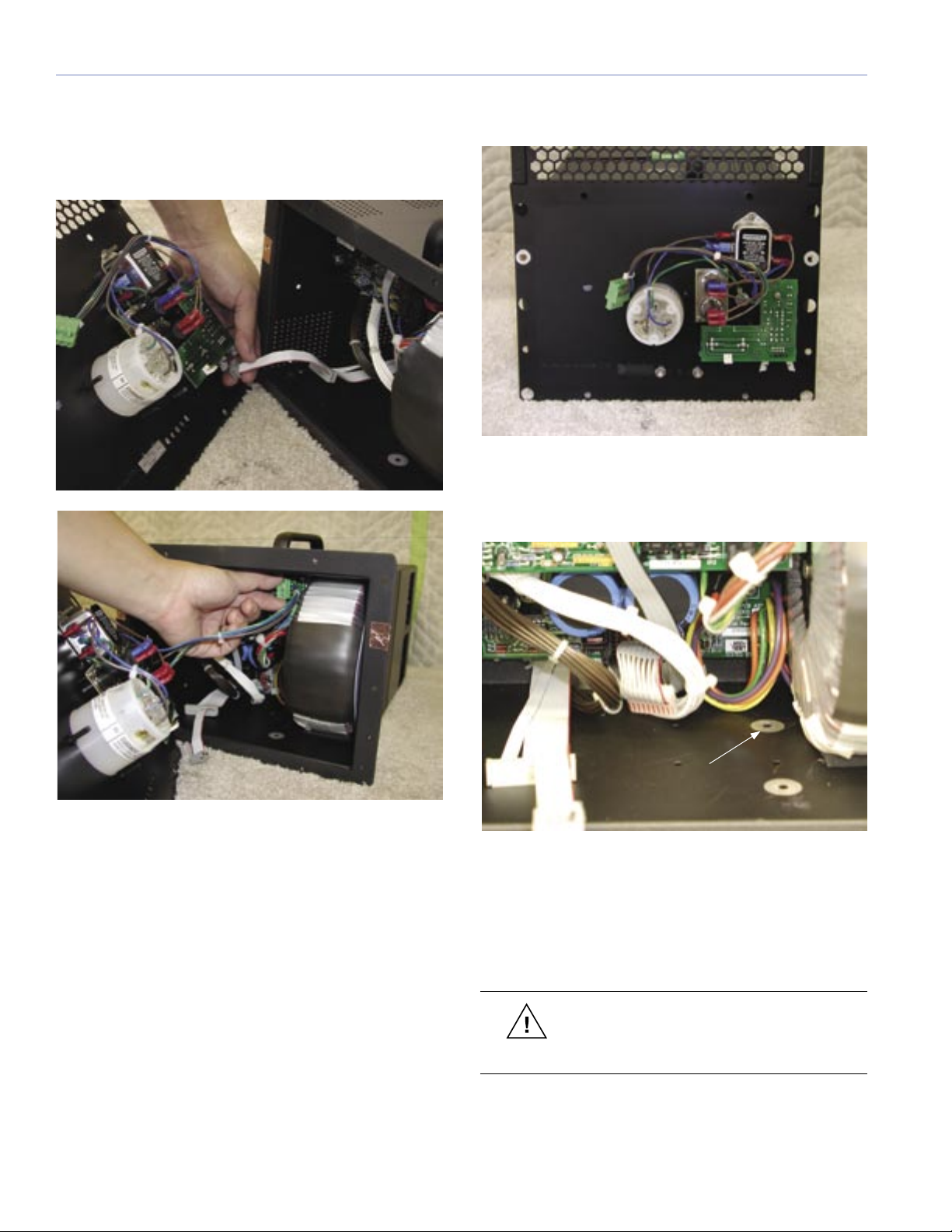
3. With the amplifier sitting on a firm surface, remove the
eight small head screws from its user panel.
Screw points for
attachment to cabinet
(four per side)
User panel attachment
screws (eight total)
CHAPTER 2: INSTALLING TRANSITION HARDWARE
16
CHAPTER 2
4. While slowly removing the amplifier's user panel,
disconnect the signal cable from the input board on
the user panel by disengaging the gray connector
and disconnect the AC input connector (4-wire green
connector) from the AC mains board.
5. Remove the blank plate from the user panel by
removing the two nuts on the back of the user panel.
6. Looking in to the power supply chassis, locate the
back right screw hole (next to the transformer) on the
floor of the power supply chassis.
back right screw hole
7. Verify that the paint around the hole is removed. If it is
not, remove a sufficient amount of paint with a Dremel
tool or sandpaper to allow for metal to metal contact
with the module standoff and the chassis floor. Make
sure that you remove all debris from the chassis when
you are done.
CAUTION: Over-thinning the metal around
the hole will make metal-to-metal contact
worse. Don’t grind down the metal too much.
Table of contents
Other Meyer Sound Measuring Instrument manuals

Popular Measuring Instrument manuals by other brands


MARTINDALE
MARTINDALE AV85 instruction manual

Milwaukee
Milwaukee 2280-20 Operator's manual

National Instruments
National Instruments PXIe-5622 CALIBRATION PROCEDURE

COLOGICX
COLOGICX PROTOGEN EGCP-03 user manual

Etatron
Etatron eSelect M 1 CD COOL Operating instructions and maintenance

Vega
Vega VEGAPULS 61 operating instructions


