Time TV-300 User manual

TV-300
MANUAL
TV-300

1G
ENERAL DESCRIPTIONS 2
1.1. Basic working principle 2
1.2. Application range 2
1.3. Technical Specifications 2
1.4. Basic configuration and Optional accessories 2
1.5. Other parameters 3
1.6. Features 3
2TECHNICAL TERMS 4
3C
ONFIGURATION 5
3.1. Description of components 5
3.2. Appearance 6
3.3. Description of main body 6
4I
NSTALLATION OF TRANSDUCER 7
4.1. Installation principle 7
4.2. Install method 7
4.2.1. Installed with bolt 7
4.2.2. Installed with magnetic base 8
4.2.3. Installed with probe 8
5HOW TO USE THE METER 9
5.1. Basic concept 9
5.2. Simple test 9
5.3. How to use the menu 10
5.4. Description of functions 11
5.4.1. Display 11
5.4.2. Analyse 11
5.4.3. View 13
5.4.4. System 13
6HOW TO USE THE ACCESSORIES 15
7T
ROUBLE SHOOTING 16
8M
AINTENANCE 17
APPENDIX 1: VIBRATION STANDARD 18
a. Rank of machine vibration (ISO2372) 18
b. Maximum vibration of motor that power larger than 1 horsepower
(NEMA MG1-12.05) 18
c. Maximum vibration of high-power induction drive motor
(NEMA MG1-20.52) 18
d. Maximum vibration of squirrel-cage induction drive motor
(API STD 541) 19
e. ISO/IS2373 Motor quality standard according as vibration velocity. 19
APPENDIX 2 VIBRATION FREQUENCY AND POSSIBLE REASON 20
Manual TV-300 1
CONTENTS

1.1 . BASIC WORKING PRINCIPLE
TV300 uses piezoelectric acceleration transducer to convert vibration signal into electric
signal. Then by analyzing input signal, results including RMS of velocity values, peak-
peak value of displacement, peak values of acceleration or real-time spectral charts are
displayed or printed out.
1.2. APPLICATION RANGE
The vibration meter is designed to test conventional vibration, especially the vibration
test in rotating and reciprocating machines. It can be used not only to test the
acceleration, velocity, and displacement of vibration as well as rev (or inherent
frequency), but also perform simple failure diagnosis.
The technical specifications of TV300 comply with the requirements of GB 13823.3.
TV300 is widely used in machinery, power, metallurgy, automobile and other industrial
fields.
1.3. TECHNICAL SPECIFICATIONS
- Measurement range
Acceleration: 0.1 m/s2- 392 m/s2 (Peak)
Velocity: 0.01 - 80 cm/s (RMS)
Displacement: 0.001 - 10 mm (Peak - peak)
- The frequency range
Acceleration: 10Hz - 200 Hz, 10Hz - 500 Hz, 10Hz - 1KHz, 10Hz - 10KHz
Velocity: 10Hz - 1KHz
Displacement: 10Hz- 500 Hz
- Accuracy: <±5%
- Temperature range: 0°C ~ 40°C
- Humidity range: <80%
1.4. BASIC CONFIGURATION AND OPTIONAL ACCESSORIES
- Basic configuration
Title Quantity
TV300 main body 1
6V/800mA ~220V/50Hz power adapters 1 (select one of them)
6V/800mA ~110V/50Hz power adapters
Vibration transducer TSV-01 1
Leather wrap 1
Package case 1
Manual 1
- Optional accessories
Title Quantity
Data Management software(with a cable) 1
Printer(with a cable) 1
Magnetic base 1
Probe groupware 1
Long needle 1
2Manual TV-300
1. GENERAL DESCRIPTION

1.5. OTHER PARAMETERS
- Display screen: LCD, 320×200 pixels, with LED backlight
- Battery's parameters:
Li battery, work 20 hours continuously. Charging time 12 hours.
- Dimensions: 171mm×78.5mm×28 mm
- Weight: 230g
1.6. FEATURES
- Three display modes: Common mode, Special mode and Spectrum mode
- The acceleration, velocity, displacement of vibration and rev (or inherent frequency)
can be tested.
- The testing meter can display measurement values in status bar according to alarm`
limit and warning limit.
- Simple failure diagnosis: Automatically raise the alarm and request to enter into
spectrum testing mode when the measurement value is beyond the limit.
- If equipped with printer, measurement value and spectral charts can be printed out.
- Measurement values and spectral charts can be analyzed with PC and software.
- Memory function: It can store 25×62 measurement values and 25 spectral charts.
- Li battery is used: The battery can charge at anytime safely and it can work
continuously for a long time after charging is finish.
- With LED backlight and auto-shutdown function.
Manual TV-300 3
1. Vibration:
A rapid linear motion of object about an equilibrium position, like piston, tuning fork
or motor.
2. Vibration displacement:
The magnitude of a vector from the initial position to a subsequent position assumed
by a body.
3. Vibration velocity:
The rate of speed of vibration.
4. Vibration acceleration:
The rate of change of vibration velocity with respect to time.
5. Vibration frequency:
The number of complete cycles of vibration per unit time.
6. Point number:
One point number correspond to one testing point, TV300 will keep up to 62 historical
results for each point.
7. Patrol test:
Test more than one point in a fixed routine. Each point correspond one testing point.
8. Warning limit:
Remind users that the vibration is beyond the limit of the safe state.
9. Alarming limit:
Remind users that the vibration is beyond the limit of the destruct status.
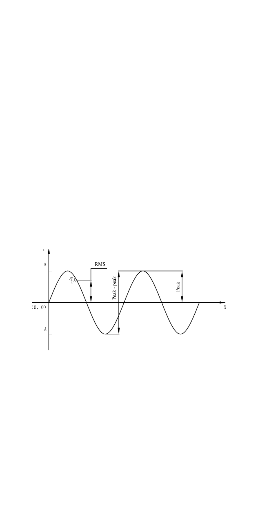
10. RMS, peak values and peak-peak values (see Figure 2-1)
11. Spectral chart:
A chart indicates the magnitude distribution of each frequency in the whole vibration.
Figure 2-1
4Manual TV-300
2TECHNICAL TERMS

3.1. DESCRIPTION OF COMPONENTS
Figure 3-1
1 Main body
2 Probe groupware
3 Long needle
4 Vibration transducer
5 Bolt
6 Magnetic base
According to different situations, the transducers maybe fixed in the probe groupware
or connected to the magnetic base (see chapter 4 in detail.).
Manual TV-300 5
3CONFIGURATION

3.2. APPEARANCE
Figure 3-2
3.3. DESCRIPTION OF MAIN BODY
Title
1 Display screen 1
2 Front cover 1
3 LCD 1
4 Keyboard 16
5 Sealed tray 1
6 Plastic frame 1
7 Front PCB 1
8 Back PCB 1
9 Back cover 1
10 Hole cover 2
11 Bolt M3 4
12 Li battery 1
13 Battery holder 1
14 Gasket M2 2
15 Bolt M2 19
6Manual TV-300
Nameplate
A sensitivity
knob- in the
hole
Display
window
Charging indicate light
RS232 socket Charging socket
Transducer socket
Keyboard

4.1. INSTALLATION PRINCIPLE
- The testing position should show the vibration characters of the object to be tested.
- The main axis of the transducers should be consistent with the direction of he object
to be tested.
- The transducers should be in close contact with the object to be tested.
4.2. INSTALL METHOD
Install method/ Install with Install with Install with
Contrast bolts magnetic base probe
Cost None low Rather high
Affection on None When roughness is When caring about
the result worse than Ra1.6, acceleration and the
the result maybe vibration frequency is
not stable. higher than 1KHz, the
result will be smaller.
Convenience Not good good Best
4.2.1. INSTALLED WITH BOLT
Application range: Screw eye has no influence on the running of the object being
tested. Usage: Drill a screw eye 5mm deep in the object being tested. Connect the
transducer to the object by bolts (see Figure 4-1). And this is the method that the
frequency response is best.
Figure 4-1
Manual TV-300 7
4INSTALLATION OF TRANSDUCER
The bolt drills through
the object being tested
Thickness δ
Vibration transducer
Bolt M5
Object being tested
Surface

4.2.2. INSTALLED WITH MAGNETIC BASE
Application range: Magnetic, flat surface, roughness less than Ra1.6, acceleration
less than 20 m/s2.
Usage: Before usage, take off the iron wafer and rubber wafer under magnetic
base (ensure enough suction), and then screw up the magnetic base on transducer
(see Figure 4-2). After usage, put back the iron wafer and rubber wafer to maintain
the magnetism.
Figure 4-2
4.2.3.INSTALLED WITH PROBE
Applications range: Frequency is less than 1KHz; vibration energy is not too small.
Usage: Connect the needle to the transducer directly by using probe groupware
(see figure 4-3)
Figure 4-3
8Manual TV-300
Surface
Vibration transducer
Bolt M5
Magnetic base
Object being tested
The surface is slick and flat The surface is rough The surface is uneven
Surface
Vibration transducer
Hold
Needle
Object being tested
Forming right angles between
the needle and the surface
The needle makes the
surfcace distortion
The mass is
too small
Forming bevel between the
needle and the surface

5.1. BASIC CONCEPT
Special display mode is as follows (see Figure 5-1).
Figure 5-1
- Battery status: The full scale indicates the power is 100%.
- Working status: When the measurement goes on, displays one moving column.
When the measurement is finished, displays "at hh : mm".
- Time: Current time.
- Measurement point number: One point number correspond to one testing point,
TV300 will keep up to 62 historical results for each point.
- Measurement values: Indicate the testing results of the acceleration, velocity, and
displacement.
- Status Bar: Indicate the relative relation of testing result, last testing result, warning
limit and alarm limit.
- Main menu: Consist of display, analyse, view and system.
5.2. SIMPLE TEST
- Press “on/off” key to power on;
Press “MEAS” key to start the testing operation (displays one moving column);
Press “MEAS” key again to finish the test;
Read the measurement values
- When testing continuously, the measurement point number can increase
automatically. Users can also choose the measurement point number by Up/Down
keys.
Manual TV-300 9
5HOW TO USE THE METER
Status
bar
Alarm
limit
Warning
limit
The last
measure
result
Time
Working
status
Battery
status
Point
number
Time
Main menu SystemAnalyse ViewDisplay

5.3. HOW TO USE THE MENU
The descriptions of the menu give as follows (adjust): ( indicates the default settings).
Left/Right keys are used to choose in the rows of the menu. Up/Down keys are used to
choose in the columns of the menu. The background color of the fonts in the menu
changing to black indicates the item is chosen. Press “OK” key to confirm the operation
or enter into the submenu, Press “C” key to cancel operation or return to upper menu.
Up, Down, Left, Right keys and Number 2,4,6,8 keys are used alternately. When
operation is on the menu, the direction keys are in use. When numbers are need, the
number keys are available.
10 Manual TV-300
Clock
About
LCD contrast - +
AUTO shotdown
English
Languages
Personal
settings
Display modes
Point increment
No
Yes / No
Common/Special /Spectrum
Veloctiy/Displacemetn / Acceleration
10-200Hz/10-500Hz//10-1KHz /10Hz-10KHz
Alarm limit
Warning limit
Yes
Limit
Transmission
bands
Parameter
Measure settings
System
Delete
Print
All records before
Current record
View
Analyse Print/Auto/Adjust/Zoom
Display

5.4. DESCRIPTION OF FUNCTIONS
5.4.1. DISPLAY
"Display" can change the display modes from common, special and spectrum
modes. It can give convenience for users to look through the data from different
way, but it does not change the default settings of display modes. If users want to
change the default settings of display modes, the submenu "Display modes" in the
menu "System" should be changed.
5.4.2. ANALYSE
When diagnosing the fault, users could use this function. Spectrum chart maybe
display like this. (See Figure 5-2)
Figure 5-2
When the measurement value is higher than the warning limit, TV300 can
automatically give an alarm and request to enter into spectrum testing mode (see
Figure 5-3).
Figure 5-3
Manual TV-300 11
SystemAnalyse ViewDisplay
NoFFT graph: YesDraw

The "Analyse" menu consists of "Print", "Auto", "Adjust" and "Zoom" four sub items.
- Print: Print out current spectral charts.
- Auto:
Peak values of the spectral chart could be automatically captured. And different
peak values could be selected by Left/Right keys. (see Figure 5-4)
Figure 5-4 A B
Figure (a) shows the peak-peak value tested is 62.6Hz, that maybe the rev of the
tested object;
Figure (b) shows the peak value tested is 109.6Hz, that maybe the inherent
frequency of the tested object;
- Manual
The values of different points in the charts can be looked through in the manual
style. The cursor position can be adjusted by Left/Right keys. The amplitude and
frequency of the point, which the cursor indicates, can be displayed.
(see Figure 5-5).
Figure 5-5
- Zoom
In spectrum analysis, the spectrum zoom function can change the frequency
resolution in the range selected by users. Firstly, to select the range of the
frequency----that is the concerned area, press Left/Right keys to move the
cursor. The cursor could move more quickly when the Left or Right key is hold.
Secondly, Up/Down keys could change the frequency resolution. The resolution
could reach 0.25Hz.
Figure 5-6
12 Manual TV-300

5.4.3. VIEW
Users can look through the measurement results stored in the memory by selecting
"View". The information of each measurement result comprises point number,
testing time and certain results (see Figure 5-7). Users could print out the list. Also,
the data can be deleted.
Figure 5-7
5.4.4. SYSTEM
5.4.4.1. Measurement settings
- Parameter: Velocity, Displacement and Acceleration. Affection of this
setting is shown in 5.4.4.3.
- Transmission bands: According to application, select the bands of frequency.
- Limit: When the limit is set, the meter could display status bar to
inspect the status of the running equipment easily. As
soon as the tested value is beyond the limit, the meter
request to enter into diagnosis (see Figure 5-2).
5.4.4.2. Point increment
If select "Yes", when a testing operation of the current point number is
finished, the point number will increase automatically, and go into the
waiting state of the next point number. Up/Down keys can also change
the testing point number.
If select "No", point number will not increase automatically. When tests
are performed continuously, the measurement results will be regarded
as different testing results of the same testing point number.
5.4.4.3. Display modes
There are three display modes: Common mode (Table 5-1, Figure 5-8),
Special mode (Table 5-2, Figure 5-9) and Spectrum mode (Figure 5-2).
Table 5-1 Common mode
Selected parameter velocity displacement acceleration
Display area RMS of velocity peak - peak value peak value of
of displacement acceleration
Manual TV-300 13

Display area/ Display area Display area Display Display
Selected parameter 1 (left) 1 (right) area 2 area 3
Velocity RMS of peak value of peak-peak peak value of
velocity velocity value of acceleration
displacement
Displacement peak-peak RMS of RMS of peak value of
value of displacement RMS of acceleration
displacement
Acceleration peak value of RMS of RMS of peak-peak
acceleration acceleration RMS of value of
displacement
Figure 5-8 Velocity-common Figure 5-9 Velocity- special
5.4.4.4. Personal settings
- Languages:
There are two languages available: Chinese and English.
- Auto shutdown:
The meter will shutdown automatically if there is no operation for a
while. And users can set the delay time themselves.
- LCD contrast:
Users can adjust LCD contrast by Left/Right keys.
5.4.4.5. Time
Time is the assistant information of the measurement results. TV300 can
automatically record the time when the test is performed. If the time is
not correct, it should be reset manually.
5.4.4.6. Software information
It consists of the model of the meter and the software identifier.
14 Manual TV-300

TV300 has accessories such as printer and corresponding software. If equipped with
printer, the printing operation can be performed. The data stored in TV300 can be
uploading to PC and do analysis with corresponding software. If PC is equipped with
printer, the data can also be printed out from PC.
TV300 connects to printer or PC through a communication cable. One end is connected
to TV300 through RS232 serial port, and the other end is connected to printer or PC
through a 9-pin connector.
How to use the software can refer to the specifications of the corresponding software.
Manual TV-300 15
6HOW TO USE THE ACCESSORIES

- When the battery cannot charge, check the charging indicating light.
- The measurement value is unstable.
1. Make sure the vibration frequency of the vibration object is in the frequency
range of 10Hz-10kHz.
2. If the magnetic base is used, pay attention to:
a. Make sure the surface of the tested object is flat, and roughness is smaller
than Ra1.6.
b. Make sure the iron wafer below the magnetic base is taken off, and the
magnetic force is enough.
- When enter the non-mother language system because of incorrect operation, users
can change back the mother language referring to the construction of the menu
(see 5.3).
If some trouble cannot be overcome, please contact to TIME Group Inc.
16 Manual TV-300
7TROUBLE SHOOTING

1. Operating environment: Strictly avoid collision, heavy dust, dampness, strong
magnetic field, oil, grease and dirt.
2. How to clean the main body of the meter: Because alcohol and other chemical
liquid can erode the main body of TV300, especial the display window, little water
can be used to clean to meter smoothly.
3. How to use the connector: Don't plug the connector of the transducers, printer or
PC, when TV300 is power on.
4. Calibration: The vibration meter is a high-precision instrument and the environment
will influence on it. So it should be calibrated periodically (half a year or one year). If
the sensitivity has changed, it can be adjusted by rotating the knob which is use to
adjust the sensitivity.
Manual TV-300 17
8MAINTENANCE
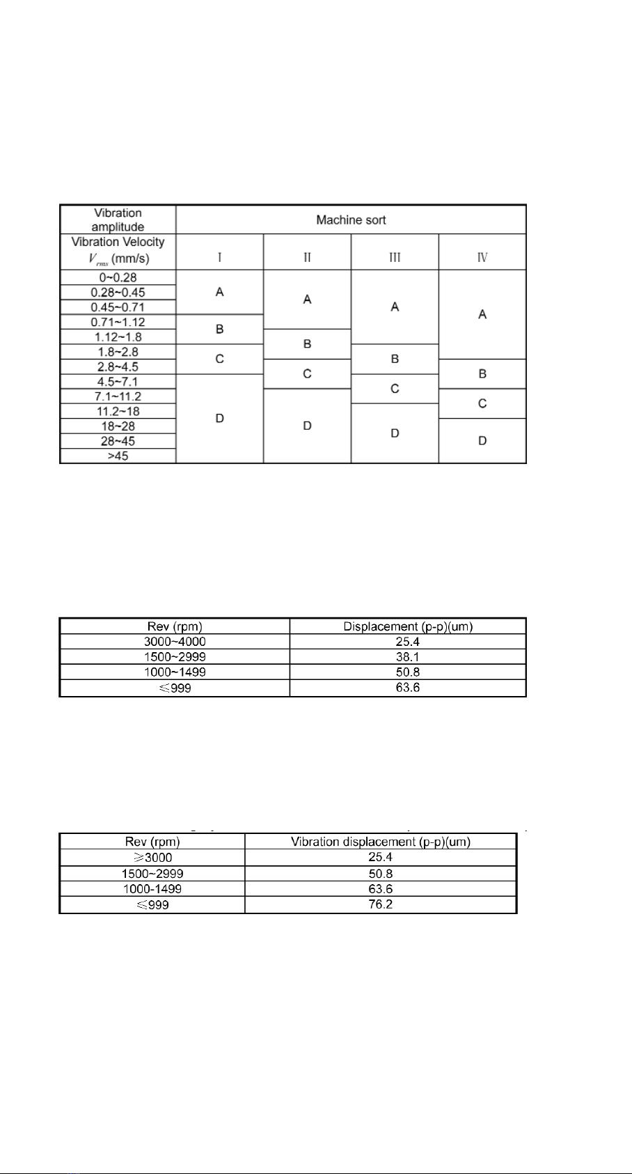
A. RANK OF MACHINE VIBRATION (ISO2372)
Note:
(1) Class I is small motor (power less than 15kW). Class I is medium motor (power
between 15kW~75kW). Class ? is high power motor (hard base); Class ? is high power motor (stretch base).
(2) A, B, C, D are vibration rank. "A" means good, "B" means satisfying, "C" means not satisfying, "D" means
forbidden. Vibration velocity should be taken from the three perpendicular axes on the motor shell.
B. MAXIMUM VIBRATION OF MOTOR THAT POWER LARGER THAN 1 HORSEPOWER
(NEMA MG1-12.05)
* For AC motor, rev is maximum synchronous rev. For DC motor, it is maximum power
rev. For motor in series, it is work rev.
C. MAXIMUM VIBRATION OF HIGH-POWER INDUCTION DRIVE MOTOR
(NEMA MG1-20.52)
* National Electric Manufacturers Association (NEMA) establishes two standards
above.
18 Manual TV-300
APPENDIX 1: VIBRATION STANDARD

D. MAXIMUM VIBRATION OF SQUIRREL-CAGE INDUCTION DRIVE MOTOR
(API STD 541)
* American Petroleum Institute (API) established this standard.
E. ISO/IS2373 MOTOR QUALITY STANDARD ACCORDING AS VIBRATION VELOCITY.
Limit of rank "N" is suitable for common motor. When the request is higher than that in
the table, limit can be gotten by dividing the limit of rank "S" with 1.6 or multiples of 1.6.
Manual TV-300 19
Table of contents
Other Time Measuring Instrument manuals


