Etatron eSelect M 1 CD COOL Instructions for use

OPERATING INSTRUCTIONS AND MAINTENANCE
IT
UK
eSelect M 1CD COOL
UNI EN ISO 9001-2008

ENGLISH
5
TECHNICAL SPECIFICATIONS OF THE INSTRUMENT ...............................................................11
INSTALLATION ..............................................................................................................................11
DESCRIPTION OF THE DISPLAY .................................................................................................15
OPERATING FUNCTIONS .............................................................................................................16
TABLE OF CONTENTS
Warnings ......................................................................................................................................... 8
Symbols used in the manual ............................................................................................................ 8
Transport and handling..................................................................................................................... 8
Intended use of the device ............................................................................................................... 8
Risks ............................................................................................................................................... 8
Assembly of the instrument ............................................................................................................. 9
Disassembly of the instrument ....................................................................................................... 9
General features .............................................................................................................................. 9
Main features .................................................................................................................................. 9
Dimensions of the instrument ......................................................................................................... 9
Main additional functions ............................................................................................................ 10
Wall installation ..............................................................................................................................
12
Diagram of electrical connections ............................................................................................... 12
Control Panel ............................................................................................................................... 14
ON-OFF mode .................................................................................................................................
16
DIRECT / REVERSE direction ........................................................................................................ 16
MIN / MAX ALARM function ........................................................................................................... 16
HYSTERESIS ........................................................................................................................ 16
DELAY output response delay on setpoint ................................................................................... 16
ANALOGUE OUTPUTS IN CURRENT 4-20 mA1 / 4-20 mA2 ...............................................................................16
TIMER IN REAL TIME / START-STOP TIME .................................................................................... 17
START-UP DELAY ........................................................................................................................ 17
FLOW SENSOR function “Proximity Sensor” ............................................................................................... 17
INSTRUMENT ESELCT M1 CD COOL ............................................................................................9
ESELECT M1 CD COOL ................................................................................................................14

6
ENGLISH
MENU SELECTION ........................................................................................................................22
PURGE MENU ................................................................................................................................23
CONDUCTIVITY SENSOR CALIBRATION > EXPERT MENU ......................................................30
ANALOGUE 4-20MA OUTPUTS ....................................................................................................31
SETTINGS ......................................................................................................................................32
SENSOR CLEANING AND MAINTENANCE AND TECHNICAL SPECIFICATIONS .....................34
TEMPERATURE .................................................................................................................... 17
ETHERNET / RS 485 communication control unit with external module ......................................... 17
Purge SV Solenoid Valve control .................................................................................................. 18
INHIBITOR control ........................................................................................................................ 19
BIOCIDE control ........................................................................................................................... 20
Other functions ............................................................................................................................ 20
Select the language of the PROGRAMMING MENU ....................................................................... 21
Select the CONSTANT K FACTOR OF THE CONDUCTIVITY PROBE ............................................... 21
TEMPERATURE settings ............................................................................................................... 22
DATE AND TIME
–
Timer in real time ............................................................................................ 22
PURGE operations by means ofinternal TIMER programming ..............................................................
23
PURGE operations by means of CONDUCTIVITY measurement ..................................................... 24
INHIBITOR METERING operations via Direct Purge function ........................................................ 26
INHIBITOR METERING operations via Purge % function ................................................................. 26
INHIBITOR METERING operations via TIMER programming function ............................................. 27
INHIBITOR METERING operations via PULSE EMITTING METER .................................................... 28
BIOCIDE 1 / BIOCIDE 2 via TIMER for programming DISPENSING CYCLES ...................................... 29
BIOCIDE MENU > PRE- PURGE >TIME LOCK................................................................................... 30
4-20mA1 / 4-20mA2 ...........................................................................................................................................................32
PROGRAMMING FUNCTIONS.......................................................................................................18
INITIAL DISPLAY ...........................................................................................................................21
INHIBITOR MENU ..........................................................................................................................25
BIOCIDE MENU .....................................................................................................................29

ENGLISH
7
Notes on CONDUCTIVITY PROBES ............................................................................................... 34
ALPHA factor / TEMPERATURE / CONDUCTIVITY ......................................................................... 34
CONDUCTIVITY sensors: Configuration and MEASUREMENT RANGE .......................................... 35
Configuration of CONDUCTIVITY PROBE wires ............................................................................ 36
Installation of LEVEL PROBES and TANKS for chemical products ............................................... 36
Suggestions for troubleshooting CONDUCTIVITY SENSORS........................................................ 37
INSTRUMENT TROUBLESHOOTING ............................................................................................36
8
ENGLISH
Warnings
Read the warnings below carefully. They provide important information regarding safe installation, use and
maintenance. Store this manual with the utmost care for future reference.
The device is built to a professional standard. Its durability and electrical and mechanical reliability will be more efficient if it is
used properly and maintenance is carried out on a regular basis.
ATTENTION: Any work or repairs inside the device must be carried out by qualied and authorised personnel. We assume no
liability due to failure to comply with this rule.
WARRANTY: 1 year (excluding parts subject to normal wear where applicable, namely: valves, fittings, pipe clamps, tubes, filter
and injection valve). Improper use of the device will void this warranty. The warranty is understood as ex-works or authorised
distributors.
Symbols used in the manual
FORBIDDEN
Precedes information regarding
safety. Indicates a forbidden
operation.
ATTENTION
Precedes very important text to protect
thehealthofexposedpersonsorthe
machine itself.
INFORMATION NOTE
Precedes information concerning use
of the device.
Transport and handling
The device must be transported as indicated on the box. Shipping by any means, even if free of carriage of the purchaser or
recipient, is carried out at the purchaser's risk. Complaints for missing materials must be submitted within 10 days of arrival of the
goods and within 30 days of receipt for defective material. If the device is to be replaced, this must be agreed upon with authorised
personnel or the authorised distributor.
Intended use of the device
The device must be solely employed for the use it has been expressly built for, i.e. to check the pH/Rx measurement. Any other
use is considered improper and therefore dangerous. The device is not intended to be used for any applications not foreseen at the
design stage. For further explanations, the customer must contact our ofces for information on the type of instrument in their
possession and its correct use. The manufacturer shall not be held liable for any damage resulting from improper, erroneous or
unreasonable use.
Risks
After removing the packaging, check the integrity of the device. If in doubt, do not use it and contact a qualified technician. The
packing materials (such as plastic bags, polystyrene, etc.) must not be left within the reach of children since they are potentially
dangerous.
Before connecting the device, make sure that the rating corresponds to that of the mains. The rating is displayed on the
adhesive label on the device itself
The execution of the electrical system must comply with the standards that define professional workmanship in the country
where the system is made.
Use of any electrical device implies observance of some fundamental rules. In particular:
▪do not touch the device with wet or damp hands or feet (e.g. swimming pools);
▪do not leave the device exposed to atmospheric agents (rain, sun, etc.);
▪do not allow the device to be used by children or persons incapable of using it without surveillance.
▪In case of failure and/or malfunctioning of the device, switch it off and do not tamper with it. For any repairs, please contact our
service centres and request the use of original spare parts. Failure to comply with the above can jeopardise the safety of the pump.

ENGLISH
9
INSTRUMENT ESELCT M1 CD COOL
▪If you decide to no longer use a device, it is recommended to make it inoperable by unplugging it from the mains.
▪Make sure it is switched off electrically (both polarities), disconnecting the conductors from the contact points of the mains by opening
the omnipolar switch with at least 3 mm between the contacts.
Assembly of the instrument
All instruments produced are normally supplied already assembled. For wall installation see paragraph “Wall assembly”.
Disassembly of the instrument
Always pay the utmost attention when disassembling the instrument or before performing maintenance on it. Always disable
electrical connections beforehand.
General features
eSelect M1 CD COOL is a multi-purpose instrument for a single parameter suitable for measurements of cooling towers,
specically designed for cooling water treatment, abatement operations of air purifiers and humidiers or any industrial conditioning
system. The controller is able to interact with other process equipment such as: a range of conductivity sensors (based on the
measurement range); flow meters; drain solenoid valves.
eSelect M1 CD COOL offers high quality performance in terms of measurements and functionality which make it extremely
versatile and easy to use such as:
- The instrument is able to work with constant K1 probes at 20.00 mS and even at 100.00 mS (the latter with graphite sensors);
the constant K5 ranges up to 2,000 μS, including other ranges from K0.8 to K10.
- Monitoring 2 modes for purge operations; 4 inhibitor metering modes; 2 Controls of biocidal product metering pumps.
Main features
▪Device manufactured according to standards
▪Case made of: ABS plastic
▪Backlit display 126x64
▪Can be fitted with level probe (to check chemicals) (not included)
▪Output relay for setpoint values
▪AUX external unit remote control output
▪RS485 / Ethernet external module connection
▪PT100 temperature sensor
▪100/240 VAC power supply 50/60 Hz single-phase (maximum ±10% uctuations are permitted); on demand 12/24 V
Dimensions of the instrument
10
ENGLISH
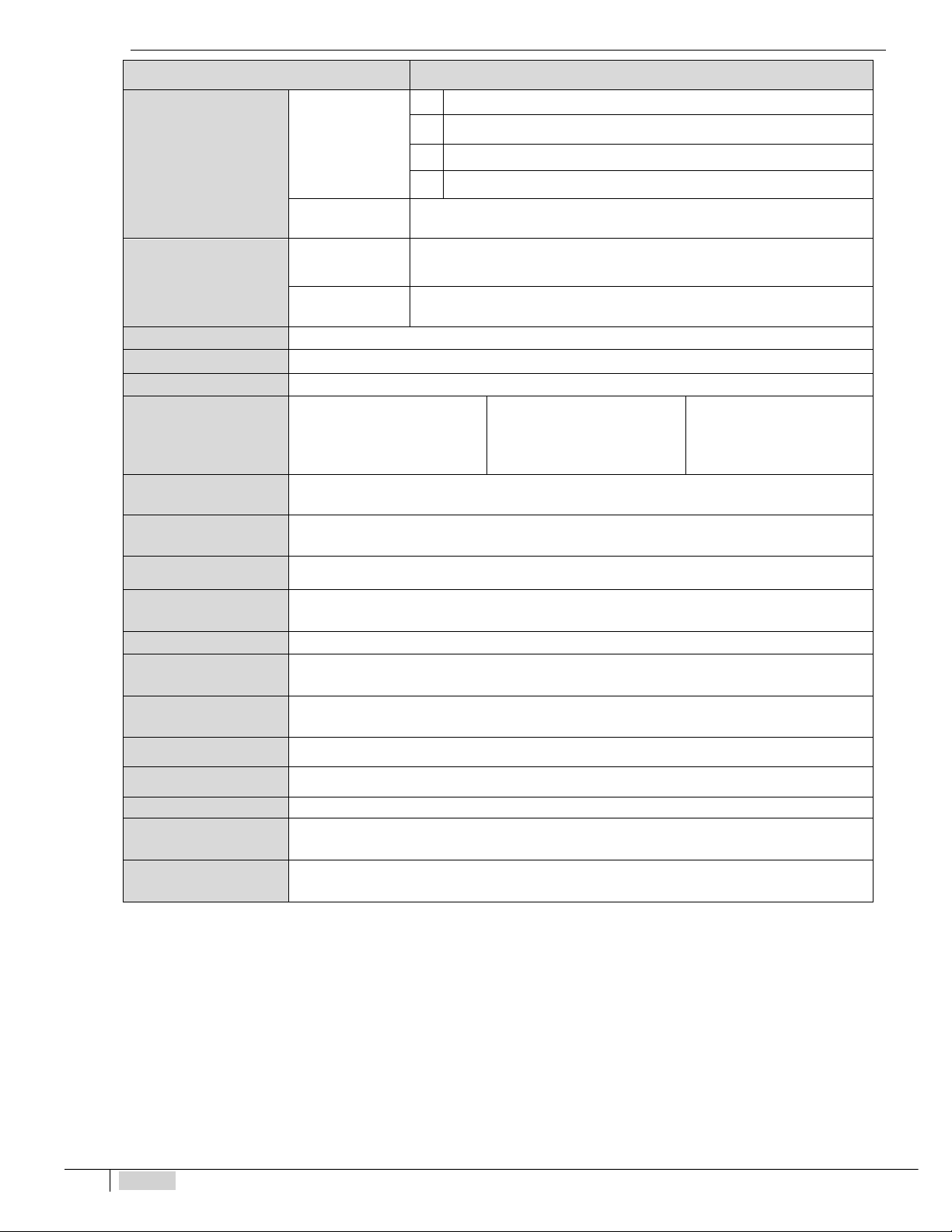
Main additional functions
Function Description
Setpoint
Relay outputs
1
SV (solenoid valve) PURGE ON-OFF / voltage-free, relay 5A max
–
230Vac
2
INHIBITORON-OFFmeteringpump/voltage-free,relay5Amax
–
230Vac
3
BIOCIDE1ON-OFFmetering pump/voltage-free,relay5Amax
–
230Vac
5
BIOCIDE2ON-OFFmetering pump/voltage-free,relay5Amax
–
230Vac
AUX Output
Relay
ALARM voltage-free contact, relay 5A max
–
230Vac
4-20 mA1-2
Outputs 0/4…20
mA1 EC
Adjustable(500 ohm maximum inputimpedance),withgalvanicseparation.
Connected to Conductivity measurement settings
Outputs 0/4…20
mA2 EC
Adjustable (500 ohm maximum input impedance), with galvanic separation.
Connected to Conductivity measurement settings
Delay on Setpoint
Relay activation delay, programmable for each setpoint (999 sec.)
FLOW Sensor
Blocks outlet operations if there is no flow in the probe socket
Level
Remote relay control to monitor the chemical additive level (level probe not included)
CE conductivity
measurement range and
K factor (cell constant)
K1 Range up to 20.00 mS
Hysteresis/PWM start-up point =
500 μS
Resolution 10 μS
K5 Range up to 2,000 μS
Hysteresis/PWM start-up point =
50μS
Resolution 1 μS
K5 Range up to 200 μS
Hysteresis/PWM start-up point =
0.50 μS
Resolution 0.1 μS
Temperature Settings
Manual or automatic offset (auto with temperature probe PT100)
▪ Resolution 0.1% °C ▪ Precision: ± 0.5% °C
Temperature probe
range
–
20 ...100°C
Relay insulation voltage
>3000 Vac
Internal electrical
protection
The power supply unit assures electrical protection (instead of the fuse)
Load
Resistive load 5A at 230VAC / Inductive load 0.5A at 230VAC
Power supply /
Consumption
Universal power supply 100
250VAC / 5W at 240VAC
Consumption / Rated
Current 230Vca 5W = 25mA ▪ 24Vca-cc=5W = 230mA ▪ 12Vcc 5W = 460mA
Display
Backlit 126x64 display; Visible display area 70x37 mm
Contact relay duration
≥5x10
4
operations (5A at 230VAC)
Noise level
Irrelevant
Environmental
conditions
Possibly dryenvironment, altitude up to 2000m, Relative humidity 80% for temperature upto 31°C
linearly decreasing to 50% of relative humidity at 40°C. Pollution degree 2.
Transport / storage
conditions
-5-60°C in dry environment
10

ENGLISH
11
INSTALLATION
CE conductivity measurement range and K
factor (cell constant)
▪ K1 Range up to 20.00 mS
Hysteresis / PWM start-up point = 500 μS
Resolution 10 μS
▪ K5 Range up to 2.,000 μS / Hysteresis / PWM start-up point = 50 μS
Resolution 1 μS
▪ K5 Range up to 200 μS / Hysteresis / PWM start-up point = 0.50 μS
Resolution 0.1 μS
Temperature settings: Manual or automatic offset (auto with temperature probe PT100)
▪ Resolution 0.1% °C ▪ Precision: ± 0.5% °C
Temperature probe range: – 20.... 100°C
Power supply / Consumption: Universal power supply 100250VAC / 5W at 240VAC
Microprocessor technology: SMD components with a 6-key digital control keypad
Linearity, Stability, Reproducibility: 0.5% in standard conditions
Display: Backlit 126x64 display; Visible display area 70x37 mm
Delay on Setpoint: Relay activation delay, programmable for each setpoint (999 sec.)
Delay on start-up: Delay in relay when the unit is switched on, programmable
Consumption / Rated Current: 230Vca 5W = 25mA ▪ 24Vca-cc=5W = 230mA ▪ 12Vcc 5W = 460mA
Internal electrical protection: Power supply unit assures electrical protection (instead of fuse)
Level / Relay remote control: Chemical additive level (level probe not included) output voltage +5VDC
RELAY 1 output: SV (solenoid valve) PURGE ON-OFF / voltage-free, relay 5Amax 230VAC
RELAY 2 output: INHIBITOR ON-OFF metering pump/ voltage-free, relay 5Amax 230VAC
RELAY 3 output: BIOCIDE1 ON-OFF metering pump/ voltage-free, relay 5Amax 230VAC
RELAY 5 output: BIOCIDE2 ON-OFF metering pump/ voltage-free, relay 5Amax 230VAC
AUX Output: ALARM voltage-free contact, relay 5A max 230Vac
FLOW sensor: Blocks outlet operations if there is no ow in the probe socket.
Outputs: Output 0/4...20 mA1 EC: Adjustable (500 maximum input impedance), with galvanic separation.
Connected to Conductivity measurement settings.
Output 0/4...20 mA2 EC: Adjustable (500 maximum input impedance), with galvanic separation.
Connected to Conductivity measurement settings.
Load: Resistive load 5A at 230VAC / Inductive load 0.5A at 230VAC
Relay insulation voltage: > 3000VAC
Contact relay duration: 5x10⁴operations (5A at 230VAC)
Noise level: Irrelevant
Operating temperature: ideal temperature 5°C-40°C, resistance up to 0°C-45°C
Environmental conditions: Possibly dry environment, altitude up to 2000m, Relative humidity 80% for temperature up to
31°C linearly decreasing to 50% of relative humidity at
40°C. Pollution degree 2.
Transport / storage conditions: – 560°C in a dry environment
Install the instrument in a dry place, away from heat sources at
a maximum room temperature of 40°C.
Comply with standards in force in the different countries
regarding electrical installation (Fig. 2). If the power cord does not
have a plug, the device must be connected to the mains by
means of an omnipolar disconnecting switch with at least 3
mm between the contacts. All the power supply circuits must
be interrupted before accessing the connection devices.
Fig. 1
–
Electrical connection
TECHNICAL SPECIFICATIONS OF THE INSTRUMENT

12
ENGLISH
Covers (A) x 4
Wall installation
The wall-mounting plugs are supplied with the device. Always use a plug suitable to the available support. The layout of the
holes to be drilled on the support is displayed in Figure 2.
Fig. 2 -Measurements for wall xing 226l x 146h
To access the 4 installation holes, remove the covers on the installation points (A) found on each corner of the
instrument, use a Phillips screwdriver to loosen the four screws underneath the covers, then open the front panel (see Fig.2).
The casing has 4 captive screws to quickly open/close the cover, thereby allowing for easy access for commissioning
and servicing, as well as assuring excellent seal for long-lasting operation
•
Install the unit in a dry place away from heat sources. Max room temperature 40°C.
•
Strictly comply with the regulations in force in the various countries regarding electrical systems.
•
Fit the instrument on the wall using the screws supplied
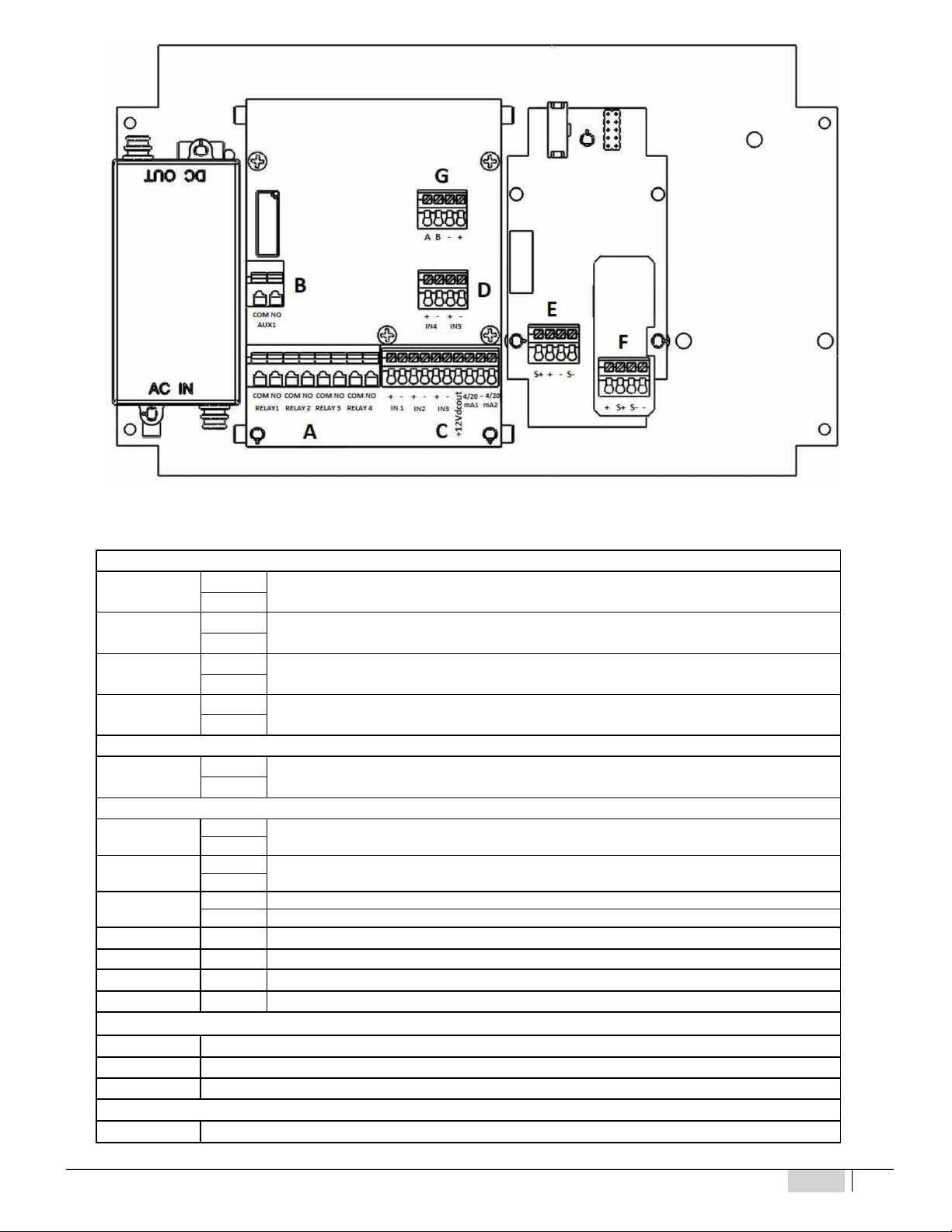
Diagram of electrical connections
To connect the accessories and peripheral devices to the instrument, remove the front cover screws, using a Phillips screwdriver
to reach the connecting terminal boards.
The terminal boards consist of spring terminals for quick coupling of the wires. Press the square “slotted” pin with a small at
headed screwdriver and insert the stripped wire in the corresponding terminal.
ATTENTION: exert slight pressure on the spring pin to avoid irreparably damaging the terminal board.
Do not connect more than one device to each pin
Run the wires to be connected through the cable glands on the case wall.
12
ENGLISH
13
Fig. 3
–
Connection diagram
TERMINAL BOARD “A”
Relay 1 COM SV PURGE Solenoid Valve
NO
Relay 2 COM INHIBITOR METERING PUMP
NO
Relay 3 COM BIOCIDE 1 METERING PUMP
NO
Relay 4 COM BIOCIDE 2 METERING PUMP
NO
TERMINAL BOARD “B”
AUX 1 COM ON-OFF ALARM relay output for external signalling device
NO
TERMINAL BOARD “C”
IN 1 +Digital input INHIBITOR level probe for the chemical tank
-
IN 2 +Pulse Emitting Meter
-
IN 3 + Proximity Sensor input BLACK wires
- Proximity Sensor input BLUE wires
+12VDC + 12 VDC output of the Proximity Sensor BROWN wire
4-20 mA1 + (+) Proportional output Conductivity 4-20mA1 for metering pump mA, PLC, data collection
-- (-) Proportional output Conductivity 4-20mA1/mA2 for metering pump mA, PLC, data collection
4-20 mA2 + (+) Proportional output Conductivity 4-20mA2 for metering pump mA, PLC, data collection
TERMINAL BOARD “D”
IN4 Digital input BIOCIDE 1 level probe for the chemical tank (+) (-)
IN5 Digital input BIOCIDE 2 level probe for the chemical tank (+) (-)
TERMINAL BOARD “E”
S + Conductivity Probe (WHITE wire)
14
ENGLISH
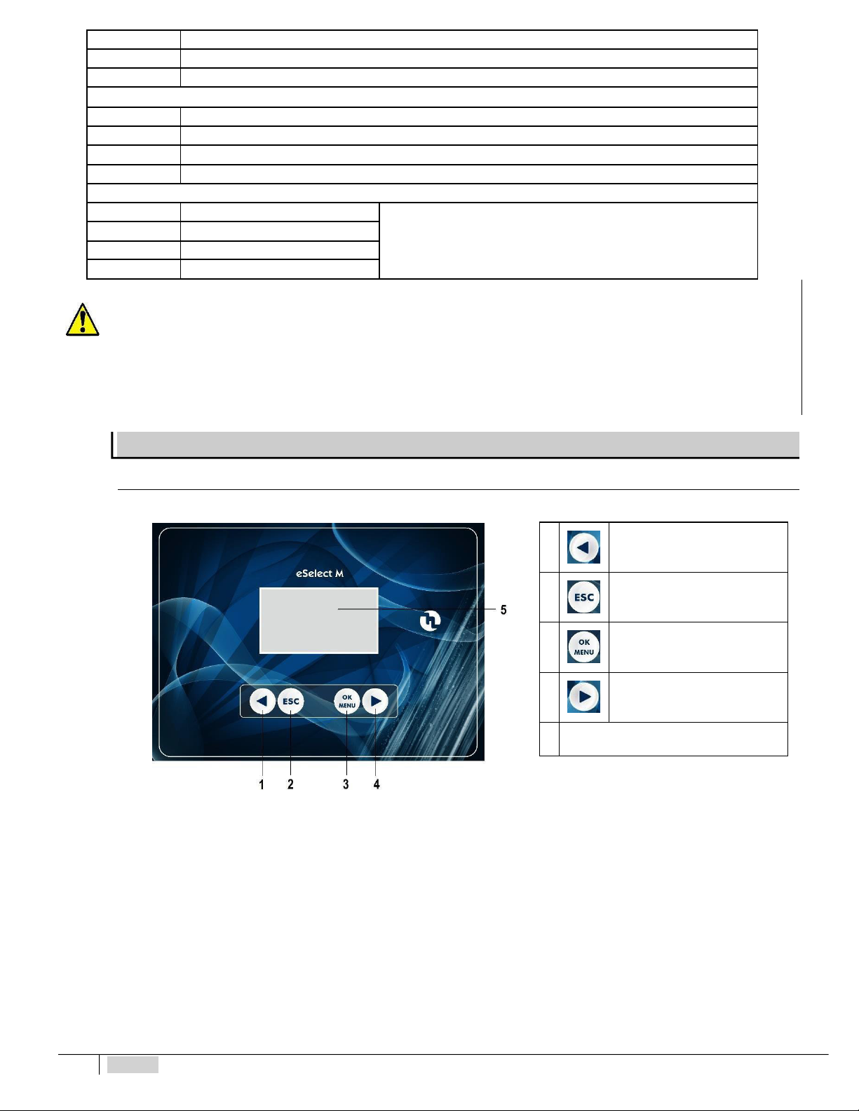
1Button to scroll the menu to the
left and decrease values
2 Button to quit the menu
3Button to enter the menu and
conrm selections
4Button to scroll the menu to the
right and increase values
5 Display
ESELECT M1 CD COOL
+White/Brown wire
-Black/Brown wire
S - Conductivity Probe (Black wire)
TERMINAL BOARD “F”
+PT100 temperature probe (RED wire)
S + PT100 temperature probe (BLUE wire)
S - PT100 temperature probe (GREEN wire)
-PT100 temperature probe (YELLOW wire)
TERMINAL BOARD “G”
AORANGE wire Connection for RS485 / ETHERNET external module.
For connection to the ETACLOUD, the external KIT CONNECT module
must be connected (NOT included with the instrument)
code KST0000101
KIT CONNECT X INSTRUMENTS SERIES M
BYELLOW wire
-BLACK wire
+Not Connected
REMEMBER:
unit with universal voltage 100-250 VAC (±10%) or 9-24VDC. If the real voltage is constantly at the limit (minimum or
maximum), or when the peaks are far above the mentioned range, the unit input is electrically protected against voltage uctuations;
outside the range mentioned above, the instrument does not work and the printed circuit must be replaced.
It is recommended
to use
voltage protections, check the earthing system and, when other equipment is connected in parallel, use a transducer. Furthermore, ETATRON
recommends
installing a UPS (genset) to assure continuity thus ensuring no data are lost. A system that is set up without following the proper
electrical design rules, without an earthing system, with frequent ON/OFF operations, might directly underminethe printed circuit.
Control Panel
The following picture shows the control panel with a description of the functions of the various keys.
Fig. 4 – Keypad
14
ENGLISH
15
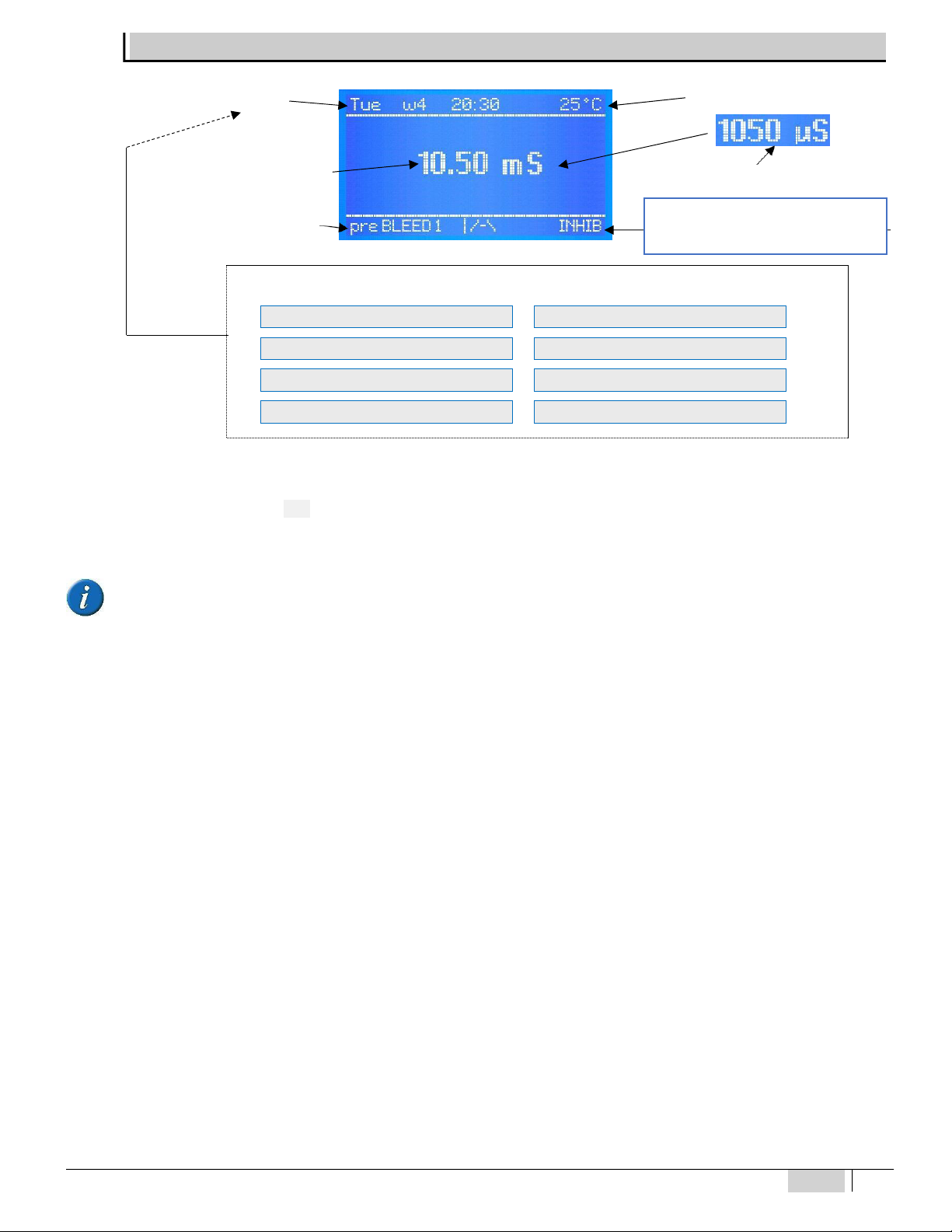
* Instrument status messages shown as follows:
Date / Time Temperature value**
Conductivity Value
in mS da 2000 µS and up
Status of the instrument
Conductivity Value
in µS up to 1999 µS
REAL DAY AND TIME INHIBITOR TANK
BIOCIDE PROGRAM BIOCIDE1 TANK
MAX EC ALARM BIOCIDE2 TANK
MIN EC ALARM NO LINK
If more than one function is active, the messages are displayed in continuous cycle, each is displayed for 3 seconds.
The ALARM or FLOW message disappears once the measurements are again consistent with the programmed settings. To remove the active
icons from the display, press and hold ESC. When the messages are displayed, the temperature value is not displayed.
NO MEASUREMENT CONNECTION LINK: communication between instrument and display down.
The software of the power and control boards of the eSelect M series are connected via the 485 protocol: when instead of the
temperature the display shows
NO MEASUREMENT CONN.
, this means there is a problem between the two boards, in that case check
the at electric cable and immediately contact the ETATRON service.
Other status icons shown at the end of the row ***
EC - MAX ALARM : Max EC conductivity value programmed in the “PURGE” menu mode = conductivity
EC - MIN ALARM : Min EC conductivity value programmed in the “PURGE” menu mode = conductivity
INHIBITOR TANK : when the Inhibitor tank reaches a low level (closed contact)
BIOCIDE1 TANK : when the Biocide1 tank reaches a low level (closed contact)
BIOCIDE2 TANK : when the Biocide2 tank reaches a low level (closed contact)
The day and time are set automatically by the instrument based on the real time selected in “SETTINGS”.
The Icon w .. is the week selected based on one of the two menus of the BIOCIDE programs, also based on the real time and date
selected in the "SETTINGS" menu
Temperature Value: if the temperature has been set up in manual mode, its value matches the one selected. If the PT100 mode has been
selected and a temperature sensor has been connected, the temperature value shown matches the real value in the system and allows for
automatic offsetting.
Other status icons shown at the end of the row ***
Other status messages are as follows:
WAIT please … : for 5 seconds after the instrument has started up
pre Purge 1/ pre Purge2:
blockstheBiocide1 or2 meteringoperationbecausetheconductivity levelishigherthanthevalueselectedinthe
“
Pre Purge
” programming step of the “BIOCIDE” menu.
BIO1 or BIO2 block:
removes all operations for Purge and Inhibitor metering immediately after dispensing Biocide 1 or Biocide 2 when the
dispensing process is completed.
Purge in standby
: all the conditions for activating the solenoid valve for the purge are in place but the SV is not open due to other active
operations, e.g. BIO block.
DESCRIPTION OF THE DISPLAY
Backlit display (126x64)
Visible display area 70x37 mm

16
16
ENGLISH
OPERATING FUNCTIONS
BIO1 or BIO2
in standby
:
the BIO metering process is in standby due to other active operations, for example pre-Purge or active Inhibitor
dispensing or Purge operation in progress.
“ | /
- \
”
This is an animated sequenced icon that moves each time the pulses are received by the unit via the pulse emitting meter.
NO FLOW
shows the absence of water flow in the probe socket of the sensor: this is only valid when using a proximity sensor and the "Flow
sensor" function is enabled.
Other status icons:
PURGE:
the SV solenoid valve is activated for purge operations
BIO1:
BIOCIDE1 dispensing operations
BIO2:
BIOCIDE2 dispensing operations
The acronyms and terms mentioned below are used in this booklet:
SV = Solenoid Valve; EC = Conductivity or Electro conductivity (also referred to as CD);
BIOCIDE = Biocide metering pump; INHIBITOR = Inhibitor metering pump; FLOW SENSOR = Proximity
ON-OFF mode
The unit features an ON-OFF mode that enables (or disables if the reverse mode is ON) the output relays of the metering
pumps, peristaltic pumps or other equipment.
ADVANTAGES: it works with the great majority of ON-OFF devices, which are also cost-effective.
DIRECT / REVERSE direction
The setpoint relays are factory set as follows:
Setpoint 3 EC: DIRECT mode, the output is active when the measured value is lower than the selected setpoint.
REVERSE mode, the output is active when the measured value is higher than the selected setpoint.
MIN / MAX ALARM function
The Alarm function (AUX1 relay) makes it possible to select the minimum and maximum values outside which the instrument triggers
an alarm.
ADVANTAGES: increasing safety measures assuring an alert if the parameters are out of control.
HYSTERESIS
Hysteresis is useful during operations to adjust the setpoints in ON-OFF mode and is used to enable or disable the output relays
when the selected hysteresis is achieved. Hysteresis is useful when there are too many quick swings around the setpoint, that might damage
the connected device. By increasing hysteresis it is possible to move away from the setpoint value in accordance with the required value.
Example with CL chlorine with range 2 Cl ppm: iftheselected setpointis1Cl ppm andhysteresisisset at0.050Clppm,thetwoactivation
values are 0.95 and 1.05 Cl ppm; within this range, the setpoint is OFF and outputs are blocked, outside this range the setpoint is ON (always
according to Direct or Reverse mode).
ADVANTAGES: assuring proper system control without straining the connected device.
DISADVANTAGES: the user must remember that the programmed hysteresis is slightly different from the required setpoint.
DELAY output response delay on setpoint
The Delay time blocks the output relays (max 999 sec. programmable) to ensure the outputs are active only when the sensor
measurements are stable, thus assuring the best results in terms of chemical balance.
ANALOGUE OUTPUTS IN CURRENT 4 -20 m A 1 / 4 -20 m A 2
The instrument features an output with signal in current in mA. The 4-20mA signal follows the settings of the Factor K cell constant
selected previously. The mA output provides two operating modes to be selected according to the system’s operational requirements:
•mA DEVICE: this is a programmable function combined with the EC conductivity measurement in real time which makes it therefore
possible to remotely monitor devices such as data loggers, PLCs, recorders or other devices suited to processing remote signals in mA. 4
mA corresponds to the minimum EC value (0 μS), 20 mA corresponds to the maximum measurable value (according
to the selected KFactor) which may be 200 μS, 2000 μS, 20 mS, 100 mS, the connected device is activated accordingly.

ENGLISH
17
•METERING ON SETPOINT: the mA output controls metering pumps suited to processing an input mA signal. 4 mA corresponds to
the minimum EC value (0 μS), therefore the connected mA unit operates at the minimum programmed capacity. 20 mA corresponds to the
maximum measured value (according to the selected Kfactor range) which may be 200 μS, 2000 μS, 20
mS, 100 mS, therefore the connected mA unit operates at the maximum programmed capacity.
•ADVANTAGES: best possible results because the pulses are extremely accurate in relation to measuredlevels.
•DISADVANTAGES: the user requires a specific metering pump or other device suited to processing an input signal in mA.
TIMER IN REAL TIME / START-STOP TIME
The Timer in real time makes it possible to control through a timer the AUX outputs for each remote device for the period selected in
the program. The operator may also program the days of activity and the exact time of
unit operations through Start/Stop programming.
START-UP DELAY
The start-up delay stops the output relays when the unit is switched on, thus allowing the sensor to polarise assuring correct
measurements (programmable).
FLOW SENSOR function “ Proximity Sensor”
Flow Sensor: if there is no water flow in the probe socket (and possibly in the system), the ow sensor (proximity sensor) disables
all outputs ensuring no chemical substance is added (DISABLED by default).
TEMPERATURE
Manual / Automatic Temperature offset (the latter with a PT100 temperature sensor) 0-100°C, the conductivity measurements will be
offset in temperature, always obtaining the exact value.
ETHERNET / RS 485 communication control unit with external module
The eSelect M series is suitable for remote control thanks to an RS485 expansion board with Modbus protocol using the ETACLOUD
software. The control unit via RS485/ETHERNET connection allows the operator to connect to the unit via a PC, a smartphone or a tablet,
change and view the programming and settings using the ETACLOUD software. The unit sends an email message once the alarm level,
overdose settings are reached, or when the maximum metering time of the metering pump has elapsed.
18
18
ENGLISH
Purge SV Solenoid Valve control
The instrument eSelect M – CD COOL offers two modes for purge operations (water drain) of the SV.
TIMER mode: for easy programming or in case of conductivity probe fault, the operator may enable the Timer mode; the SV is driven by the
internal timer regardless of the conductivity reading in the cooling tower.
Purge: TIMER mode
Mode Selection
Selects the operational mode to drive the purge SV: the two modes are via
Timer
built into the instrument
or via the
Conductivity
measurement.
Cycle time
Selects the intermediate time between two purge operations.
Cycle duration
Selects the opening cycle of the purge SV.
Flow Sensor
Enables or disables the Flow sensor function (proximity probe).
Max Manual Time
Overwrites the previous SV programming (timer or conductivity), selecting the maximum SV opening time
and manual start-up (next step). It is asafety measure inthe casewhere the operator opensthe SVvia
the Max manual programming and forgets to close it.
Manual ON / OFF start-up
Supersedes the previous Max Manual Time programming and SV programming (timer or conductivity).
The operator manually selects when the SV is ON and OFF. "Manual ON / OFF start-up" only works if the
previous function" Max Manual Time" has been programmed.
CONDUCTIVITY mode: processes the conductivity level to control purge operations; the displays show the measured EC values and drives the
relay output connected to the SV solenoid valve. Electroconductivity is monitored by a setpoint: once this is reached, the instrument commands
solenoid valve opening and drains the desalinated and conditioned water. NOTE: for EC conductivity measurements, the display shows μS
values up to 1999 (micro Siemens), then they change automatically into mS (milli Siemens) above the value of the latter.
CONDUCTIVITY MODE
Mode Selection
Selects the operational mode to drive the purge SV: the two modes are via
Timer
built into the instrument
or via the
Conductivity
measurement.
High Setpoint
Sets the setpoint at the highest value, after reaching which the relay closes (opens the SV)
Low Setpoint
Sets the setpoint at the lowest value, after reaching which the relay opens (closes the SV)
Max opening time
Maximum opening time of the purge valve: it is a safety mode that replaces the conductivity measurement
in the event of EC probe fault or other defects.
Max Alarm
If the EC measurement exceeds the selected
Max
value, the relay is closed and the alarm message is
displayed. The alarm is independent ofthe chosendirection (direct / reverse), viarelay 4,it controls an
external signalling device.
Min alarm
If the EC measurement is below the selected
min
value, the relay is closed and the alarm message is
displayed. The alarm is independent ofthe chosen direction (direct/ reverse), viarelay 4,it controls an
external signalling device.
Direction
Direct
,theoutputisactivewhenthemeasuredvalueislowerthantheselectedsetpoint.
Reverse
,the
output is active when the measured value is higher than the selected setpoint
Flow Sensor
Enables or disables the Flow sensor function (proximity probe).
Max Manual Time
Overwrites the previous SV programming (timer or conductivity), selecting the maximum SV opening time
and manualstart-up(next step). Itisa safety measure inthecasewherethe operatoropensthe SVvia
the Max manual programming and forgets to close it.
Manual ON / OFF start-up
Supersedes the previous Max Manual Time programming and SV programming (timer or conductivity).
The operator manually selects when the SV is ON and OFF. "Manual ON / OFF start-up" only works if the
previous function" Max Manual Time" has been programmed.
ON-OFF mode: The unit features an ON-OFF mode which activates (or deactivates in the event of reverse mode ON) the output relays
connected to the ON-OFF equipment such as SV (solenoid valve).
RELAY 4 ON-OFF RELAY OUTPUT: The relay 4 output may be connected to the alarm device (buzzer or light) or to other equipment.
ADVANTAGES: increases safety measures providing an alert if the parameters are out of control.
MIN / MAXALARM: The Alarm function makes it possible to select the minimum and maximum values outside which the instrument goes into alarm mode.
To restore the alarm function, wait for the measurement to go back to the setpoint
ADVANTAGES: increases the safety measures assuring an alert if the parameters are out of control.
PROGRAMMING FUNCTIONS

ENGLISH
19
INHIBITOR control
The instrument eSelect M – CD COOL offers four modes for inhibitor metering operations.
DIRECT PURGE: starts dispensing the inhibitor when the purge SV is open (works parallel to the SV)
DIRECT PURGE
Mode Selection
DIRECT PURGE:
the inhibitor is dispensed
during SV
purge operations.
Max Metering time
Selects the maximum inhibitor dispensing time.
Flow Sensor
Enables or disables the Flow sensor function (proximity probe).
Max Manual Time
Overwrites the previous SV programming (timer or conductivity), selecting the maximum SV opening time
and manual start-up (next step). It is a safety measure in the casewhere the operator opens the SV via
the Max manual programming and forgets to close it.
Manual ON / OFF start-up
Supersedes the previous Max Manual Time programming and SV programming (timer or conductivity).
The operator manually selects when the SV is ON and OFF. "Manual ON / OFF start-up" only works if the
previous function" Max Manual Time" has been programmed.
% PURGE: The inhibitor is dispensed after the SV closes for a time based on the SV opening percentage equal to the duration of the last purge
operation.
PURGE %
Mode Selection
PURGE %:
the inhibitor is dispensed on the percentage basis of the last SV opening.
Max Metering time
Selects the maximum inhibitor dispensing time.
Purge % supply
Sets the SV time percentage for draining; this is the time corresponding
to inhibitor dispensingoperations.
Flow Sensor
Enables or disables the Flow sensor function (proximity probe).
Max Manual Time
Overwrites the previous SV programming (timer or conductivity), selecting the maximum SV opening
time and manual start-up (next step). It is a safety measure in the case where the operator opens the
SV via the Max manual programming and forgets to close it.
Manual ON / OFF start-up
Supersedes the previous Max Manual Time programming and SV programming (timer or conductivity).
The operator manually selects when the SV is ON and OFF. "Manual ON / OFF start-up" only works if
the previous function" Max Manual Time" has been programmed.
TIMER: controls inhibitor dispensing operations via the internal timer: at the start of each period, a metering pump injects a selected volume of
inhibitor for a preset time. During SV drain operations, inhibitor dispensing stops.
TIMER
Mode Selection TIMER: controls inhibitor dispensing operations via the internal timer.
Pause Period
During this period the inhibitor metering pump is stopped.
Metering time
Selects the inhibitor dispensing time.
Flow Sensor
Enables or disables the Flow sensor function (proximity probe).
Max Manual Time
Overwrites the previous SV programming (timer or conductivity), selecting the maximum SV opening
time and manual start-up (next step). It is a safety measure in the case where the operator opensthe
SV via the Max manual programming and forgets to close it.
Manual ON / OFF start-up
Supersedes the previous Max Manual Time programming and SV programming (timer or conductivity).
The operator manually selects when the SV is ON and OFF. "Manual ON / OFF start-up" only works if
the previous function" Max Manual Time" has been programmed.
METER: The function is active during topping up of mains water and is driven by the instrument which controls the meter pulses in line,
dispensing the inhibitor in a manner proportional to the inlet water flow.
NOTE: the meter function requires using a proportional metering pump suited to processing input digital contacts generated by a pulse
emitter water meter.
METER
Mode Selection
METER
is a function connected to the meter pulses, dispensing the inhibitor in a manner proportional to
the inlet waterow.
Pulse Start
Selects the pulse from the meter to start injecting by the inhibitor metering pump.
Metering time
Selects the inhibitor dispensing time.

20
ENGLISH
Flow Sensor
Enables or disables the Flow sensor function (proximity probe).
Max Manual Time
Overwrites the previous SV programming (timer or conductivity), selecting the maximum SV opening
time and manual start-up (next step). It is a safety measure in the case where the operator opens the
SV via the Max manual programming and forgets to close it.
Manual ON / OFF start-up
Supersedes the previous Max Manual Time programming and SV programming (timer or conductivity).
The operator manually selects when the SVis ON and OFF. "Manual ON / OFF start-up" only works if
the previous function" Max Manual Time" has been programmed.
BIOCIDE control
The instrument eSelect M – CD COOL offers two modes for two Biocide metering operations.
Most cooling tower systems include two biocide programs to assure efcient disinfection quality.
NOTE:
the Biocide function requires using an On-O metering pump suited to processing the input contacts generated by the internal
timer.
BIOCIDE 1 / BIOCIDE 2
Edit programs
Enables or disables the Biocide metering program via the real-time timer.
Program
The program in biocide mode offers many programming steps that assure more accurate metering
operations and with absolute precision (up to 99 programs for each biocide).
Setting
Pre-Purge
Pre-Purge is a safety function: if the conductivity level
is
lower than the selected EC setpoint (High
Setpoint
)
it allows the drain operation before dispensing the biocide and after disabling the purge SV. It prevents
wasting chemical biocides uselessly in the event the SV should open at the same time, during or just before
the start of the biocide activation time.
Time lock
Output time lock mode: SV purge, inhibitor dispensing and Biocide2 dispensing operations are blocked for
the duration of the Biocide1 dispensing operations, thus preventing a waste of the chemical product while
allowing its disinfection cycle to be completed at the same time.
Flow Sensor
Enables or disables the Flow sensor function (proximity probe).
Max Manual Time
Overwrites the previous SV programming (timer or conductivity), selecting the maximum SV opening time
andmanualstart-up(nextstep).Itisasafetymeasureinthe casewheretheoperatoropenstheSVviathe
Max manual programming and forgets to close it.
Manual ON / OFF start-up
Supersedes the previous Max Manual Time programming and SV programming (timer or conductivity). The
operator manually selects when the SV is ON and OFF. "Manual ON / OFF start-up" only works if the
previous function" Max Manual Time" has been programmed.
Other functions
Calibration
Calibration menu of the Conductivity sensor and PT100 temperature sensor.
Manual or automatic temperature oset is useful for conductivity measurement.
4-20 mA outputs
Controls the data logger, PLC, recorder or devices suited to processing the mA signal.
Real-time clock
Sets the date and exact time driving the internal timer according to the real-time clock
Flow Control
Selects the ow sensor (proximity probe): the ETATRON ow sensor is normally open (NO). This status must be
enabled while commissioning from the SETTINGS menu.
Level Control
TheeSelect M
–
CDCOOLoffers3levelcontrolsthatallowtheusertoconnect3floatlevel probesthatcontrolthe
meteringtankleveloftheinhibitorandbiocidemeteringpumps1and2.Whenthelowlevelindicatedbythefloatis
reached, the connected metering pumps are stopped, the alarmrelay is opened and a message is displayed.
20
ENGLISH
21
NOTE FOR THE PROGRAMMER:
Read the manual before starting programming or always have it at hand to be sure you are making the
correct selections.
IMPORTANT: if no keys are pressed for 60 seconds, the instrument will show the current measurement.
To go forward quickly, press and hold one of the ◄► buttons
The software version is shown when the instrument is on the lower part of the display.
The software is subject to revisions without notice.
The instrument is prepared for measuring and is then ready to operate.
At this stage, certain status messages might be displayed, which might be active because of current measurements, just go on
programming.
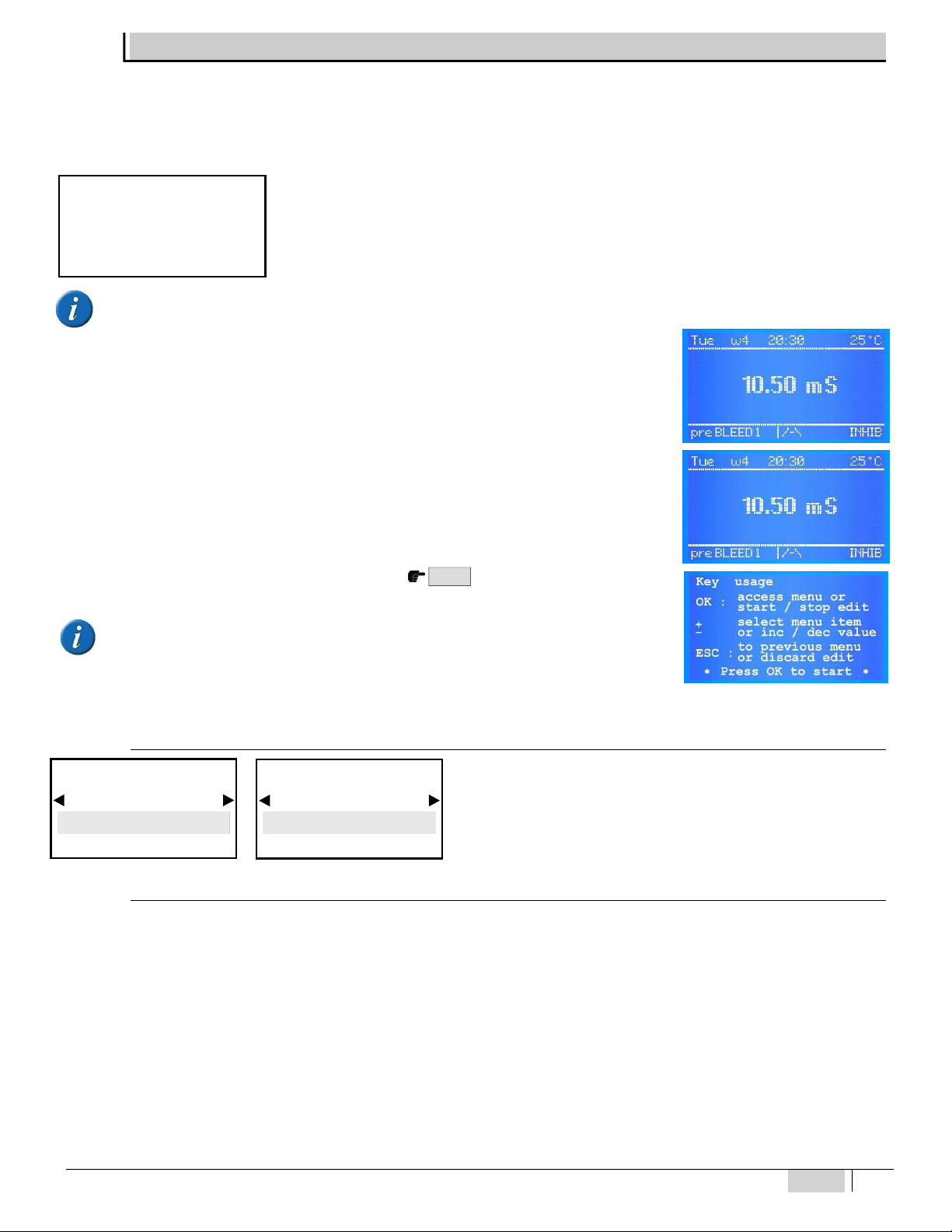
The INITIAL DISPLAY shows the measurements according to the selected K range. If the instrument has
already been programmed, the display shows the programs selected previously.
The CONTINUOUS MEASUREMENT DISPLAY shows the measurements of the parameter, the status of the
functions and the alarm indications.
When the instrument is switched on for the first time, a list of functions of all keys is displayed. This screen
is no longer displayed during subsequent start-up operations.
READ THE MESSAGE CAREFULLY, THEN PRESS OK TO START.
USE OF THE KEYS
OK: access to the menu, start/stop, selection and editing
selects the step of the menu or increases / decreases the value
ESC: goes back to the previous menu or does not save the change
* Press OK to start*
To go forward quickly, press and hold one of the ◄► buttons IN ENGLISH
Select the language of the PROGRAMMING MENU
To select the language of the programming menu.
After selecting the Language (ITALIAN, ENGLISH), the programming menu
adapts accordingly.
Select the CONSTANT K FACTOR OF THE CONDUCTIVITY PROBE
The instrument is adjusted based on cell constant “K” of the probe in use.
IMPORTANT: it is essential for the user to know the cell constant of the probe, provided by its manufacturer.
STANDARD OPERATIONAL CONDUCTIVITY RANGES
-K1 up to 20.00 mS (20,000 μS)
-K5 up to 2,000 µS
ON REQUEST other measurement ranges are possible only after approval by ETATRON D.S.:
> K0.8 up to 100 mS (100,000 µS):the latter by means of probe with graphite electrode.
> K10 up to 200 µS with probe suitable to measure thisrange.
IMPORTANT: the K1 probe with range 20,000 μS, also makes it possible to measure low conductivity levels, example up to 200 µS, but in these
cases the values are indicative because resolution will be less accurate. However, the same concept does not apply to the other range, example:
K5 probe may never measure values above its maximum range, i.e. 2.000 µS.
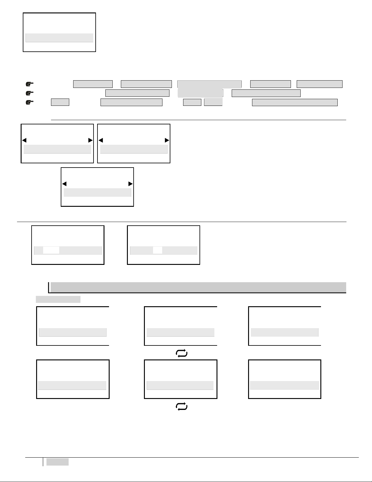
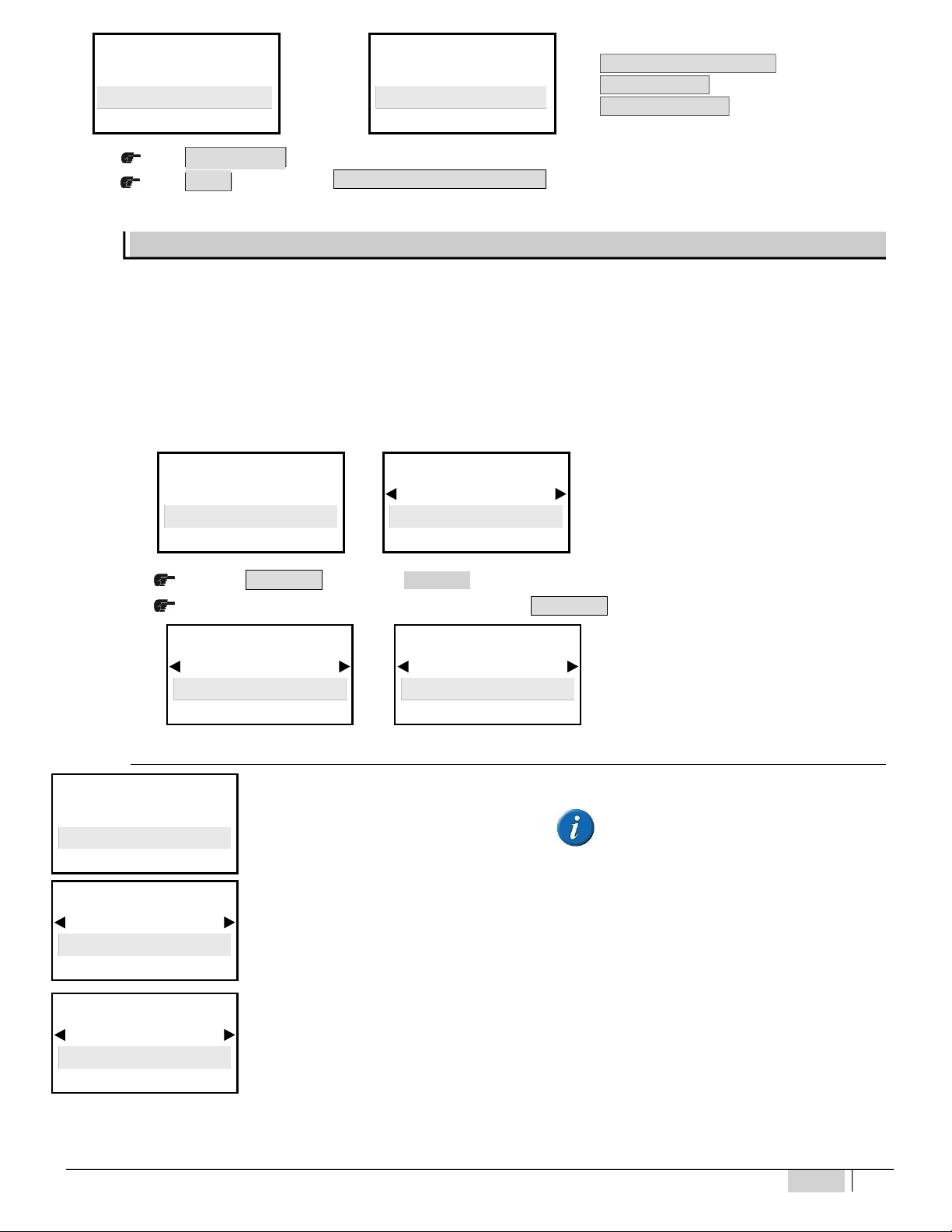
INITIAL DISPLAY
CONTROLLER SETTINGS
Language
English
BASIC MENU
SETTINGS
Lingua
Italiano
MENU BASE
ETATRON
Model eSelec M1
Rev. X. X
22
ENGLISH
S E T P O I N T 1
M E N U S E LE C T I O N S E T P OI N T 1S E T T I NG S
MENU SELECTION
The cell constant K default set at 1,000, press ◄► to edit the K value.
K1 select 1,000
K5 select 5,000
The display shows the value in μS but if the selected value exceeds 1999 μS, it will show 2.00 mS
IMPORTANT: ensure the selected K value matches that of the conductivity sensor in use.
The instrument adapts the measurements and display resolution based on the type of selected probe.
In case the user should wish to change the cell Constant Factor K, even during operations, act as follows:
BASIC menu > >
from EXPERT menu go into >
> > >
> >
Press to go back to
TEMPERATURE settings
or press to go back to
One of the following functional modes can be selected:
Manual:
The value is set by the user (0-100°C ) in the conguration menu, it is the
reference parameter for offsetting the pH value
Automatic:
The value measured by the PT100 probe is the reference parameter for
offsetting the chlorine value
DATE AND TIME
–
Timer in real time
◄Date
2017 May 14 ►◄ Time
12: 02 ►
Some applications might require programming activation
or deactivation of the device. This is why the electronic
device is equipped with a clock and calendar.
The MENU SELECTION conguration includes all the following steps:
◄Menu Selection
SV PURGE ► ◄ Menu Selection
Inhibitor ► ◄ Menu Selection
Biocide 1 ►
◄Menu Selection
Biocide 2 ► ◄ Menu Selection
Calibration* ► ◄ Menu Selection
4 - 20 m A1 ►
Se�ing Meas. CE
Const.K EC probe
1 , 000
SETTINGS
Temp. Sensor
Automatic
SETTINGS
Temperature
25 ° C
SETTINGS
Temp. Sensor
Manual
ESC M E A S U R EM E N T D I S P L A Y
M E N U S E LE C T I O N
ESC
C o n s t . K EC p r o b eM E N U S E LE C T I O N
C o n s t . K EC
ESC
E X P E R T M E N U
20
ENGLISH
23
O K / M E N U
O K/ M EN U
O K / M E N U
M E A S U R EM E N T D I S P L AY
SV PURGE MENU
Mode Selection
Timer
SV PURGE MENU
Mode Selection
Conductivity
◄Menu Selection
4 - 20 m A2 ► ◄ Menu Selection
Settings ►
* Selecting setting
C o n s t . K EC p r o b e ,
S E T P O I N T 1 and
C A L I B R A T I O N will be followed by the
values in the selected K range
Press
Press
to confirm the selection and to go on to the next sub-menu.
to go back to the
The instrument offers two modes for purge operations (water drain) of the SV.
-TIMER mode: for easy programming or in case of conductivity probe fault, the operator may enable the Timer mode; the SV is driven by the
internal timer regardless of the conductivity reading in the operating Cooling tower.
-CONDUCTIVITY mode: processes the conductivity level to control purge operations; the displays show the measured EC values and drive
the relay output connected to the SV solenoid valve. Electroconductivity is monitored by a setpoint: once this is reached, the instrument
commands solenoid valve opening and drains the desalinated and conditioned water.
The first step requires enabling the drain SV (solenoid valve):
◄Menu Selection
SV PURGE
►
SV PURGE MENU
Mode Selection
Disabled
NOTE: by selecting Disable it is not
possible to program the BLEED menu,
therefore press ESC to quit
Press to go into the SV PURGE menu
Use the arrows ◄ ► to select the required mode, press to confirm
PURGE operations by means of internal TIMER programming
The Timer mode drives the SV via the internal timer regardless of the conductivity value in the cooling tower.
Selects the intermediate time between two purge operations.
PURGE MENU
Menu Selection
SV PURGE
SV PURGE MENU
Mode Selection
Timer
SV PURGE MENU
Cycle time
00 : 00 ( h: m)
ESC
Table of contents
Other Etatron Measuring Instrument manuals


