Meyer Sound Microphones User manual

CONSTELLATION INSTALLATION GUIDE
Microphones, Processors, and
Loudspeakers
Please visit www.meyersound.com for release notes, software
updates, and forum support.

Copyright ©2008 Meyer Sound Laboratories
05.166.005.01 A2
Constellation Installation Guide
Published 2009-Feb-05
The contents of this manual are furnished for informational purposes only, are subject to change without notice, and
should not be construed as a commitment by Meyer Sound Laboratories Inc. Meyer Sound assumes no responsibility
or liability for any errors or inaccuracies that may appear in this manual. Except as permitted by applicable copyright
law, no part of this publication may be reproduced, stored in a retrieval system, or transmitted, in any form or by any
means, electronic, mechanical, recording, or otherwise, without prior written permission from Meyer Sound.
Galileo, Compass, TruShaping, and Composite EQ are trademarks and Meyer Sound, Meyer Sound MAPP Online and
SIM are registered trademarks of Meyer Sound Laboratories Inc. (Reg. U.S. Pat. & Tm. Off.). All third-party trademarks
mentioned herein are the property of their respective trademark holders.
Printed in the U.S.A.
ii

TABLE OF CONTENTS
About This Document v
Chapter 1: Power Requirements 1
Building Power 1
Equipment Rack Power 2
Power Specifications 3
Chapter 2: Wiring Installation 5
Conduit 5
MM-4XP Cabling 6
Microphone Cabling 6
Polarity 7
Chapter 3: Loudspeaker Locations and
Installation 9
Loudspeaker Locations and Installation 9
Loudspeaker Installation 13
Chapter 4: Microphone Locations and
Installation 15
Microphone Placement 15
Microphone Details and Accessories 15
Microphone Installation 18
Chapter 5: Constellation Processor Installation 21
Choosing an Equipment Rack 21
Installing Processors in the Equipment Rack 21
Chapter 6: System Control Options 25
Chapter 7: Initial System Tests 27
Setting Up CueStation 27
Routing Signal to Outputs 28
Using Wild Tracks as a Signal Source 29
Checking Signal on Microphone Inputs 29
Chapter 8: Meyer Sound Technical Support 31
iii

PREFACE : ABOUT THIS DOCUMENT
This guide will take you through the installation process of all Constellation components, in
preparation for the calibration tuning phase. Each component has unique requirements for
power, audio signal, and best wiring practices. Follow all of the guidelines in this manual to
guarantee the highest-quality sound for your venue.
There are several main components to a Constellation system:
Constellation Processors
The Constellation processors provide all of the audio processing and signal routing functions
necessary for a Constellation system. The processors are typically rack-mounted in an
equipment room with other audio components. See Chapter 5, Constellation Processor
Installation (p. 21) for more information.
Constellation Loudspeakers
Constellation loudspeakers can be mounted directly on a surface or hidden within a
back-can. Your Constellation design will specify the exact number and type of loudspeakers
required for your venue's Constellation system. Loudspeaker installation instructions can
be found in Chapter 3, Loudspeaker Locations and Installation (p. 9).
Constellation Microphones
Constellation microphones are typically hung from the ceiling, or surface-mounted on a
wall or ceiling. Your Constellation design will specify the exact number and type of
microphones required, as well as their placement within the venue. Microphone installation
instructions can be found in Chapter 4, Microphone Locations and Installation (p. 15).
System Control
Each Constellation system will include a method for the client to select Constellation
settings. This may include a simple touchscreen mounted on a wall, a web page, or direct
control of the system through CueStation™software. Installing a control device may require
a network or serial connection to the Constellation processors. See Chapter 6, System
Control Options (p. 25) for more information.
v

CHAPTER 1: POWER REQUIREMENTS
The type, quality, and correct connection of the electrical system that will be used to supply
power to the Constellation system is very important. The effect of poor, inadequate, or low-quality
power will have a detrimental result in the sound quality of the system. The following information
is the Meyer Sound specification for proper powering of the various components of a
Constellation System.
Building Power
A dedicated transformer or a balanced power transformer of adequate size for the Constellation
system shall be attached to the building power system. The ground conductor of the transformer
will be connected directly to the ground used by the building’s main service transformer. All of
the ground wires of the Constellation electrical system will be joined at the dedicated transformer.
An uninterruptible power supply should be placed in-line with the output of the transformer. It
should be of adequate size and type to provide enough current for an appropriate amount of
time to continue to meet the systems power needs in the event of power disruption to the input
of the transformer. Check with your electrical engineer to properly size this transformer.
At the grounding point of the ISO transformer, the chassis ground, or mechanical ground, the
isolated ground, and the neutral buss will be connected. The chassis or mechanical ground will
connect the sub-panels, conduit, enclosures, racks, etc.
The neutral bus, through the distribution and sub-panels, will be connected to the neutral
terminal of all electrical sockets or the neutral connector of equipment.
The isolated ground will NOT be connected to any electrical panel, conduit, or any other
conductor EXCEPT for the ground connection to a piece of equipment through its power supply
cord or directly to the chassis of the equipment.
The chassis of equipment connected to the isolated ground system shall not have contact with
any material that is connected to the chassis or mechanical ground. This includes structural
steel, aluminum studs, and non-isolated racks.
No microphones, loudspeakers, Constellation processors, computers, monitors, termination
blocks, XLR connectors, or any other equipment associated with the Constellation system can
come in contact with any conductive material that is attached to any of the building’s chassis
1

or mechanical ground system or the Constellation electrical systems’chassis or mechanical
ground. This will prevent the “shorting”of the Constellation system’s isolated ground system.
Equipment Rack Power
The equipment racks for the loudspeaker power supplies and Constellation processors should
be isolated from any other conductive material and connected directly to the isolated ground.
Using a PVC connection box and rubber feet on your rack will isolate the power source and
keep the isolated power ground from touching common power ground.
Insulate all cables in the rack room from conduit and extraneous grounds. Do not tie the shell
of cable type microphone connectors to shield except within microphones themselves.
Connectors which utilize their shells as conductors for shield, i.e., 3-circuit phone jacks, shall
be insulated from their mounting plate.
Because of the great number of possible variations in grounding systems, it shall be the
responsibility of the contractor to follow good engineering practice, as outlined above, and to
deviate from these practices only when necessary to minimize crosstalk and to maximize
signal-to-noise ratios in the audio and control systems.
The electrical contractor, along with the system contractor, shall be responsible for confirming
that the technical ground is properly electrically bonded to the building technical ground system.
It is not acceptable to use wall plugs for the rack installation; always use AC distribution inside
the rack. Because electrical code may vary from state to state and country to country, always
check with your electrical engineer and the laws in your area for specific code requirements.
2
CHAPTER 1: POWER REQUIREMENTS

Power Specifications
It is important to make sure that each powered component receives the required amount of
electrical power.
Matrix3 Processors
The Matrix3 Constellation processors require 200 watts maximum per unit.
Stella-188 Power Supply
The Stella-188 Power Supply can supply power for up to 16 Stella-4 loudspeakers, or 8
Stella-8 loudspeakers. Current draw: Burst Current (<1 sec) 5.2 A rms (115V AC), 3 A rms
(230 V AC), 6.7 A rms (100 V AC)
MPS-488E Power Supply
The MPS-488E Power Supply can supply power for up to 8 MM-4XP loudspeakers, through
5-pin SwitchCraft EN3 connectors. Current draw: Burst Current (<1 sec) 15 A rms (115 V
AC), 7.5 A rms (230 V AC)
3
CONSTELLATION INSTALLATION GUIDE

MPS-488P Power Supply
The MPS-488P Power Supply can supply power for up to 8 MM-4XP loudspeakers, through
5-pin Phoenix connectors. Current draw: Burst Current (<1 sec) 15 A rms (115 V AC), 7.5
A rms (230 V AC)
Multiple power supplies should be installed in the rack with no empty spaces between them.
The power ratings for all Meyer Sound products can be found online at
http://www.meyersound.com, listed by individual product.
4
CHAPTER 1: POWER REQUIREMENTS

CHAPTER 2: WIRING INSTALLATION
The installer should be a recognized experienced local installer with a good track record of
previous related installations. Meyer Sound does not authorize companies for product installation;
however, Meyer Sound expects all installation companies to follow universal standards set out
by NSCA, NAB, and other universally accepted standards.
Conduit
When installing Constellation wiring, be sure to use the NSCA or similar guide lines for installation
of low voltage wiring. Use no wire tuggers please! Microphone cable, digital cable, and most
low voltage cabling can not withstand tuggers without damage to the wiring itself.
Except where otherwise shown in Contract Documents, use separate conduits for following
circuits:
■Microphone-level (below –30 dBu, 20 Hz to 20kHz)
■Line-level (–30 dBu to +24 dBu, 20 Hz to 20 kHz)
■Loudspeaker (greater than +24 dBu, 20 Hz to 20 kHz)
■Control (switching or synchronous, DC from 0 to 50 volts, AC from 0 to 48 volts)
■AC power (greater than 48 volts, 60 Hz)
CAUTION: Microphone and line level conduit should not run parallel to AC power
conduits within 36”if possible.
5
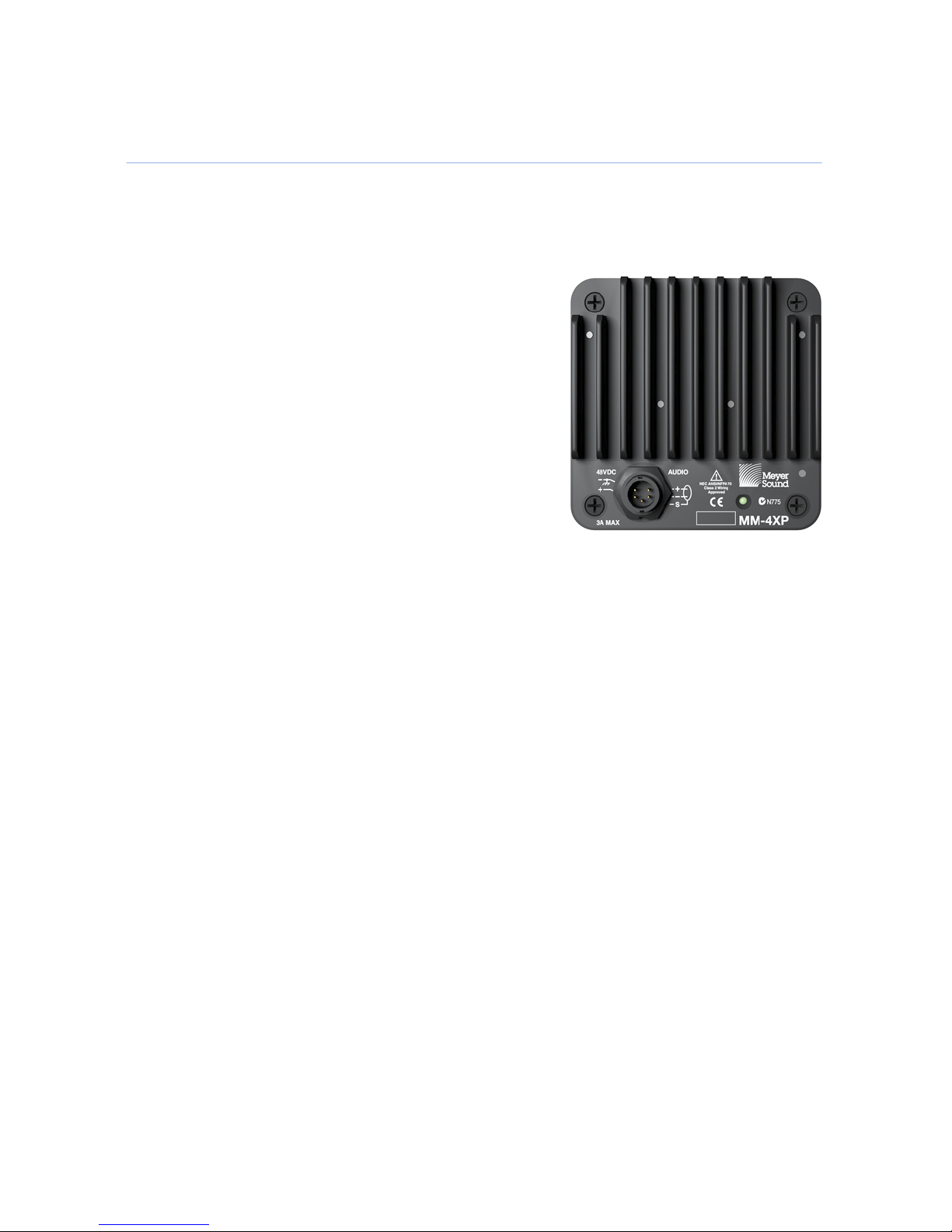
MM-4XP Cabling
The MPS-488(E/P) MM-4XP power supply provides both audio signal and power to the MM-4XP
loudspeakers. To connect the signal conducts of the Belden 1502 cable to a Phoenix connector:
1. Follow insulation stripping lengths.
2. Connect the shield to pin one at both ends of the cable.
Do not “lift”the ground conductor at either end.
3. When stripping insulation do not nick the insulation of
individual conductors.
4. Completely remove any exposed foil shield.
5. Protect the conductors from shorting against any other
conductor by using heat shrink or Teflon tubing on the
ground conductor.
6. Apply heat shrink at the point that the exterior jacket exposes the individual conductors.
Microphone Cabling
When connecting the signal conductors of the microphone cable to the XLR connector for
connection to the Constellation microphones:
1. Connect the shield to pin one at both ends of the cable. Do not “lift”the ground conductor
at one end. Do not attach ground connector to the chassis of the XLR connector. When
stripping the outer insulation, make sure to not damage the insulation of individual conductors.
2. Completely remove any exposed foil shield.
3. Protect the conductors from shorting against any other conductor by using Teflon tubing on
the ground conductor. Apply heat shrink at the point that the exterior jacket exposes the
individual conductors. Do not strip more insulation away from the individual conductors than
is necessary to have maximum contact with the solder cup of the XLR connector.
4. Pre-tin all three solder cups of the XLR connector and the wire conductors before making
the solder connection between the two. Do not overheat the wire conductors, as this may
cause melting of the insulation.
6
CHAPTER 2: WIRING INSTALLATION

Polarity
Polarity must be maintained between all microphone and loudspeaker cables. Follow the “pin
two is hot”standard for wiring balanced lines. Maintain continuity of shields at all connecting
points, except as required by standard specified practice for “floating”shields.
7
CONSTELLATION INSTALLATION GUIDE

CHAPTER 3: LOUDSPEAKER LOCATIONS AND
INSTALLATION
Loudspeaker Locations and Installation
Loudspeaker placement will be specified in the Constellation system design. The Meyer Sound
representative will provide plans showing the exact placement of each loudspeaker and
microphone within the venue. If there are conflicts in any drawings or conflicts in field locations
due to other equipment, please notify the consultant and Meyer Sound representative
immediately with those conflicts so the issue may be resolved.
IMPORTANT: Please do not make any unauthorized field changes. This will affect the
performance of the system. Any changes to the location of a loudspeaker or microphone
must be approved by the acoustical consultant and Meyer Sound. In most cases, the
architect should also be notified. Notifications must be in writing.
Mounting an MM-4XP
Mounting an MM-4XP on a surface typically requires a U-bracket and a wiring box.
9
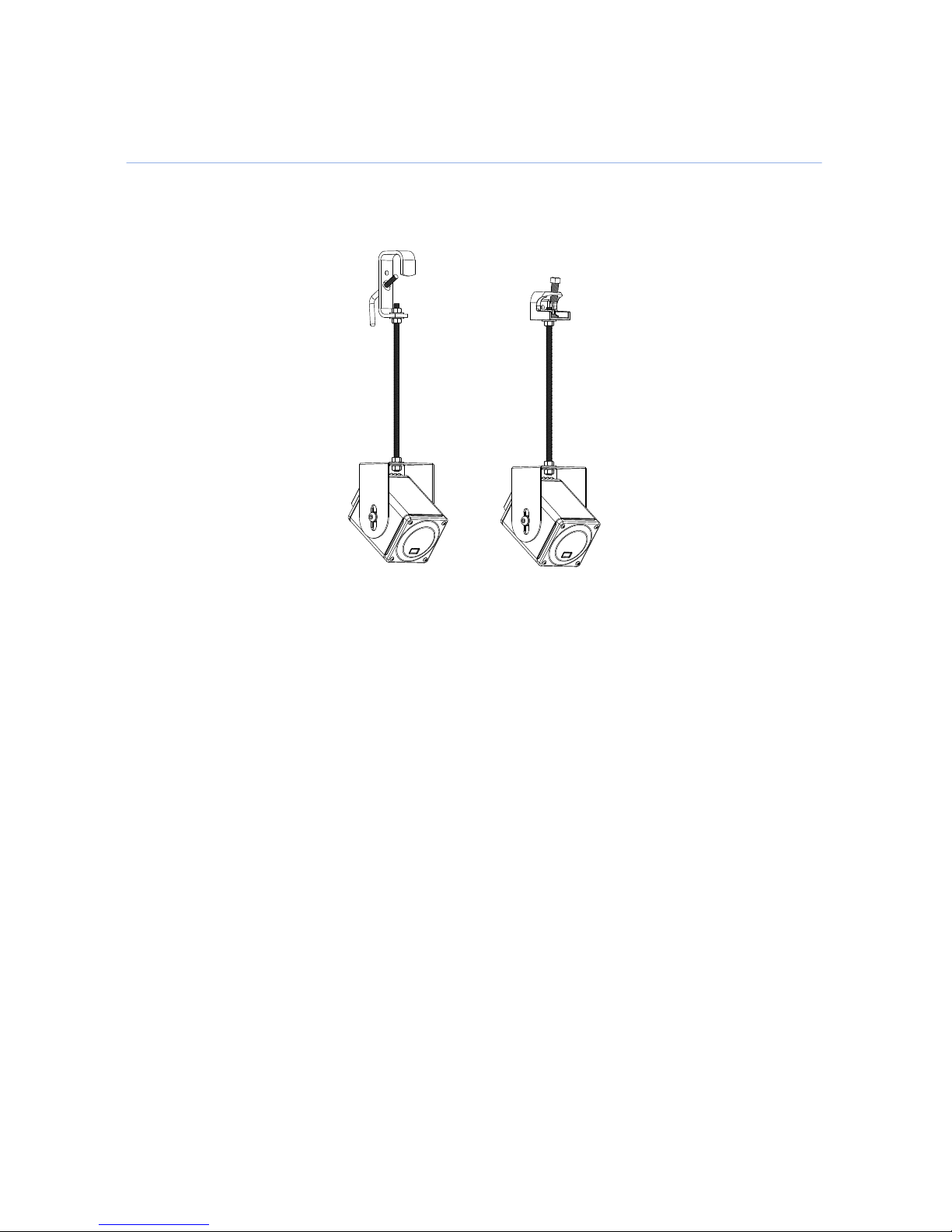
Hanging an MM-4XP from a pipe may require an all-thread extender. The all-thread can be
attached to a pipe using a C-clamp or a beam clamp:
10
CHAPTER 3: LOUDSPEAKER LOCATIONS AND INSTALLATION
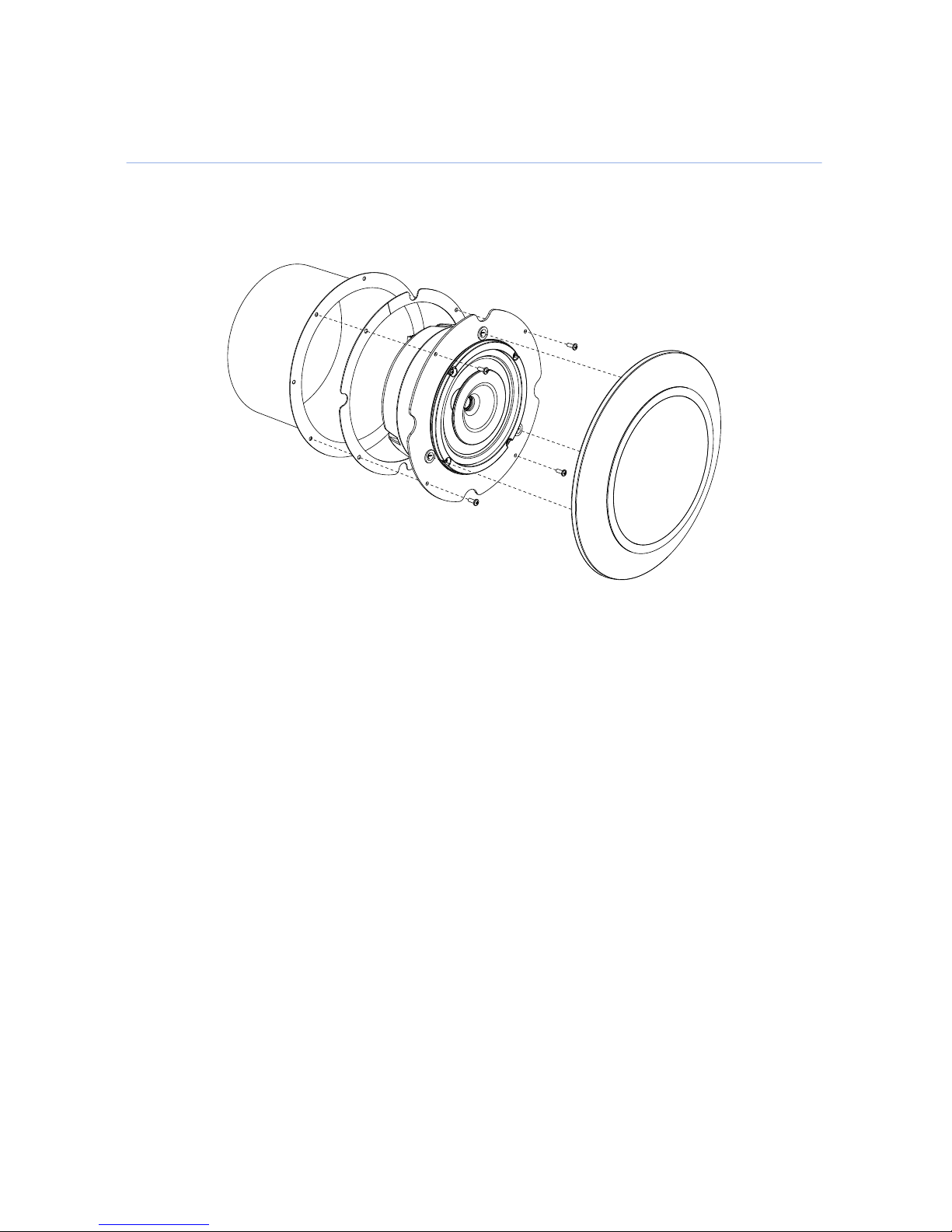
Mounting a Stella-8C
This diagram shows an exploded view of the Stella-8C.
11
CONSTELLATION INSTALLATION GUIDE
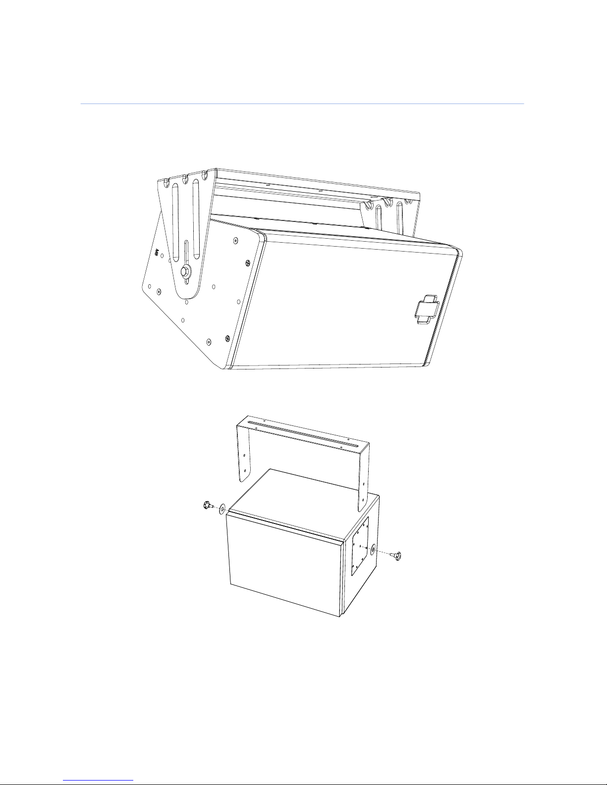
Mounting UltraSeries Loudspeakers
This diagram shows a UPJunior with the mountable U-bracket.
This diagram shows the UMS-SM with mountable U-bracket.
12
CHAPTER 3: LOUDSPEAKER LOCATIONS AND INSTALLATION

Loudspeaker Installation
One of the things that makes the Constellation system sound so natural is that it regenerates
the physical acoustics of a room. As a consequence, the resulting quality of a Constellation
system is dependent on the quality of the physical acoustics of the space. Make sure all mounts
for loudspeakers are secure, tight and free from buzzes, rattles, and acoustic distortion. Isolate
with rubber mounting where necessary. Use rated materials wherever and whenever possible.
Meyer Sound loudspeakers will mount with any standard available mounting hardware or beam
clamp available in hardware outlets around the world. Most American manufacturers of hardware
will have a load rating stamped on the hardware itself. Use at least a 5:1 ratio to calculate loads.
(for instance, if you have a 100 lb. load, use a 500 lb. rated clamp.) Although non-stamped
hardware may well be suited for your application, if there is no stamped rating it may be a
liability if the hardware fails.
Carefully document and identify all buzzes, rattles and objectionable distortion in room finishes
or fixtures. Ask the general contractor to correct all causes of such defects, if possible. Always
notify the architect, consultant, and Meyer Sound representative indicating the cause of each
issue and suggested corrective procedures. Keep a written history of room problems in case
they show up again later.
13
CONSTELLATION INSTALLATION GUIDE

CHAPTER 4: MICROPHONE LOCATIONS AND INSTALLATION
Microphone Placement
As with the loudspeaker locations, each microphone’s location is specified by the Constellation
system design. If there are conflicts in any drawings or field locations due to other equipment,
please notify Meyer Sound and your consultant immediately with those conflicts so the issue
may be resolved.
Microphone Details and Accessories
Three Constellation microphones are offered; a compact cardioid, a miniature cardioid, and a
miniature omni. All Constellation microphones consist of the capsule, 10 meters of cable, and
are terminated by a microdot connector. A microdot to XLR adaptor is supplied with the
microphone.
The miniature cardioid microphone looks like this:
15

The miniature omni microphone looks like this:
The compact cardioid microphone looks like this:
The XLR connector that terminates these microphones has a barrel that is approximately 3"
long. It looks like this:
16
CHAPTER 4: MICROPHONE LOCATIONS AND INSTALLATION

Dimensions of the miniature capsules are shown below:
Miniature OmniMiniature Cardioid
A shock mount is available for the compact cardioid. The compact cardioid capsule is shown
with the shock mount below:
17
CONSTELLATION INSTALLATION GUIDE

Microphone Installation
Make sure all mounts for microphones are secure and tight. Use rated materials wherever
possible. Try to maintain as much distance as possible from electrical equipment and fixtures,
without modifying the microphone placement guidelines. Be aware of large transformers, as
well as high voltage lighting instrument locations. These devices may still have an impact on
the performance of the microphones.
Most microphones can hang in place suspended by their own wire. Suspending a microphone
that is tied to a piece of 1/8”all-thread works very well for rigid applications and for judging
elevations at a particular location. All-thread is a common construction material and is available
with many accessories such as a sturdy beam clamp for attachment to existing steel. All-thread
comes in a variety of lengths and sizes.
The Constellation system requires a large number of Constellation microphones to be installed
using various methods depending on location and type of microphone being used. In all cases,
special attention is needed regarding the ground of the signal path attached to the microphone.
Pin-1 of the signal, otherwise known as Ground, should have only one path between the output
of the microphone and the ground terminal of the Constellation processor. If alternate ground
paths exist via wiring or connectors, increased noise, usually hum, will be added to the system
and will have to be corrected. Many times this involves re-installing cabling or providing insulation
to connectors to prevent connection to other grounds or conductors.
In an effort to prevent these kinds of installation faults, the following guidelines need to be
practiced:
■Starting at the microphone, the metallic parts of the microphone capsule should not come
into contact with any conductive material. This will provide a connection of the signal
ground to the mechanical ground of the building or other ground path, which can induce
noise at the microphone input of the Constellation processor.
■The metal shell of the XLR that is connected to the microphone is attached to signal ground.
Pin-1 of this connector is tied to the chassis of the connector. This XLR connector, and all
others, must be insulated so that they cannot come into contact with any other material
that could provide an alternate ground path, including other XLR connectors attached to
other microphones.
■Combining of Pin-1 conductors at a terminal block is not permitted.
■When using an input type XLR patch box to accept a number of individual microphone
inputs and combine them into one multi-core cable/snake, the box should be tested for
18
CHAPTER 4: MICROPHONE LOCATIONS AND INSTALLATION
This manual suits for next models
1
Table of contents


