Meyer 550 Series Guide

1
292-K-002 Rev A
Eecve 6-16-2017
Series 550
Meyer Insulaon Blower
INSTALLATION, OPERATION &
MAINTENANCE INSTRUCTIONS
Wm. W. Meyer & Sons, Inc.
1700 Franklin Blvd • Libertyville, Illinois 60048-4407 • 800-963-4458 • 847-918-0111 • Fax: 847-918-8183
e-mail: sales@meyerinsulaon.com · websites: hp://www.meyerinsulaon.com or www.wmwmeyer.com
2
TO THE OWNER, AND INSTALLATION, OPERATION AND MAINTENANCE PERSONNEL
The safety of the operator and those people that may come into contact with the equipment is of great
importance to Wm. W. Meyer & Sons, Inc. “Meyer”. The decals, shields, guards and other protecve
features designed, furnished or recommended for this machine are there for your protecon.
BEFORE aempng to install, operate or perform maintenance on this Equipment READ carefully and
UNDERSTAND all safety instrucons contained in this set of Instrucons in addion to all applicable
government safety/health laws and regulaons and generally recognized industry standards. The
operaon and maintenance of this equipment should be restricted to only those personnel trained in
its use. Consult Factory for the availability of manuals in other languages.
Installaon, Operaon and Maintenance personnel should READ carefully and UNDERSTAND the
secons of this Instrucon Manual relevant to the work they are performing. The various precauons
and recommendaons detailed within this manual are not necessarily all inclusive. These instrucons
are intended to provide general safety and operaonal guidance relang to typical uses with which
Meyer is familiar. Addional informaon may be provided that pertains to your specic piece of
equipment upon request.
SAFETY FIRST!
Indicates the presence of a hazardous situaon that, if not avoided, WILL result in
death or serious injury.
Indicates the presence of a hazardous situaon that, if not avoided, COULD result in
death or serious injury.
Indicates the presence of a hazardous situaon that, if not avoided, COULD result in
minor or moderate injury.
Indicates informaon that is important, but is not related to a parcular hazard.
TABLE OF CONTENTS
Safety Precauons ...................................................................................... 2
Applicaons - Intended Use of Equipment ................................................. 6
Receiving and Uncrang ............................................................................. 6
Specicaons.............................................................................................. 6
Operang Instrucons................................................................................ 8
Maintenance............................................................................................. 10
Troubleshoong........................................................................................ 11
SECTION I
SAFETY PRECAUTIONS

3
1-1 GENERAL SAFETY INFORMATION
• Equipment is to be operated by trained qualied personnel only.
• Always read and follow the operang and safety procedures.
• Do not operate without all guards and safety equipment installed in the proper locaon and in
working order.
• Do not disable any safety features. They are there for your protecon.
• Always use qualied personnel when repairing or maintaining the equipment.
• Do not leave the equipment unaended while it is running.
• Do not wear loose clothing or jewelry when operang this equipment. Long hair should be conned
by a hat or a hair net.
• Do not operate under the inuence of alcohol or drugs.
• If a malfuncon should occur, turn the machine o immediately and correct the problem, before
restarng the machine.
FOLLOW THESE SAFETY INSTRUCTIONS.
Emergency Shut Down Procedure
Push the E-Stop Buon in and the red panel light will come on. This will stop the machine completely.
Before connuing operaon you must determine the reason for the E-Stop. Turn the engine ignion
key to the OFF posion and remove the key. Disconnect the fuel line and close the vent on the fuel
tank. Disconnect the negave baery terminal and secure it using the lockout box. Follow your
employer’s Lockout\Tag out procedures. Aer the issue has been idened and corrected the machine
may be put back into operaon.
1-2 INSULATION MACHINE SAFETY
• Limit the operaon only to those personnel trained in the proper use and operaon of the
machinery.
• Never operate the machine without proper venlaon.
• Keep all clothing and your body away from the rotang equipment.
• Obey all safety labels and instrucons axed to the machine. Do not point discharge hose at
anything other than empty space, do not place hand(s) or any objects in material discharge stream.
• Never run the machine speed faster than the factory sengs.
• Always wear proper protecon when handling the baery. This includes eye protecon proper
gloves and proper clothing.
• Always wear proper personal protecve equipment including but not limited to eye protecon,
hearing protecon, respirator and gloves.
• Do not smoke while operang the machinery.
• Prior to performing any service or maintenance follow MACHINE SAFETY SHUTDOWN
INSTRUCTIONS.
If there are any quesons as to the safe operaon of this equipment, please do not hesitate to contact
us at 1-800-963-4458.
4
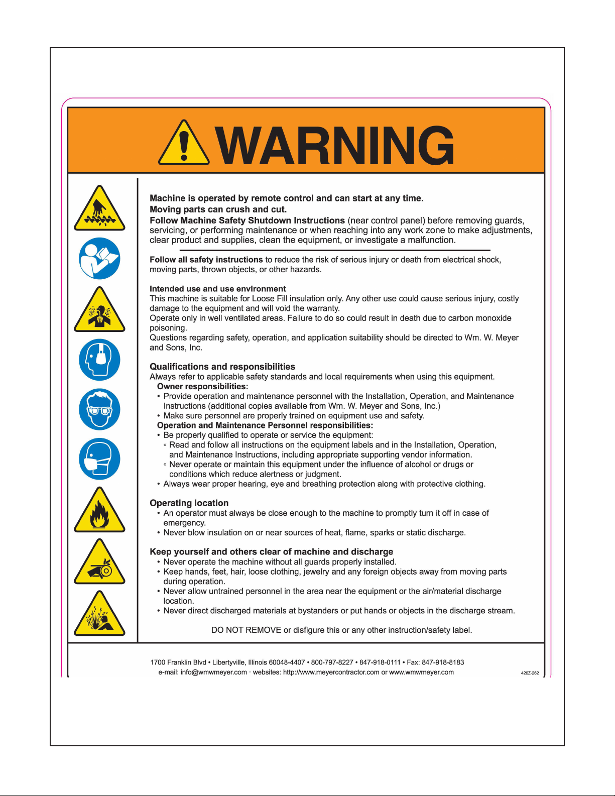
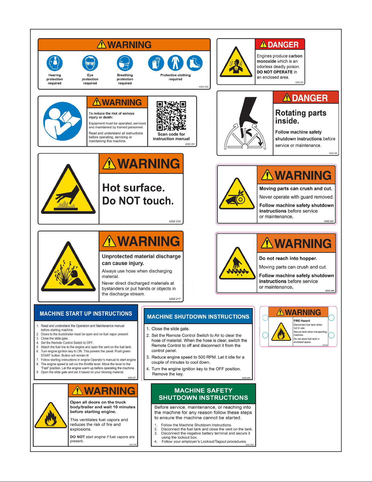
1-3 SAFETY LABELING
5

6
3-1 RECEIVING YOUR MACHINE
Immediately check the condion of your new machine as received. The unit was shipped in perfect
condion and should arrive the same way. Ownership of the goods was transferred to the carrier
as soon as it le our dock. Your order may have shipped on mulple skids, verify your count equals
that of the Bill Of Lading. If there are any missing items or visible problems, mark them on the Bill Of
Lading that the carrier has and call their oce immediately before the driver leaves your premises.
Meyer cannot le a claim on your behalf; however, please let us know by phone and wring about any
problems so that we can assist you with immediate replacement parts or informaon.
3-2 UNCRATING YOUR MACHINE
1. Carefully remove all shipping materials from the machine.
2. Check that all parts are included as stated on the Packing List that came with your shipment.
3. If anything is missing for any reason, please contact Wm. W. Meyer & Sons immediately.
4. If the equipment or goods are discovered to be damaged in a shipment at a later date, contact the
carrier and Wm. W. Meyer & Sons immediately.
SECTION III
RECEIVING AND UNCRATING
SECTION II
APPLICATION - INTENDED USE OF EQUIPMENT
The MEYER Model 551 INSULATION BLOWING MACHINE is designed to process and blow all of the
currently available loose ll berglass and cellulose insulaons on the market today.
NOTICE: This equipment must be used only for the purpose for which it was
intended. Any other use could cause bodily injury to the operator, costly damage to
the equipment and void the warranty.
SECTION IV
SPECIFICATIONS
EQUIPMENT SPECIFICATIONS
WIDTH: 63”
DEPTH: 42 1/2”
HEIGHT: 59”
WEIGHT: APPROX. 1,100 LBS.
7
MACHINE COMPONENTS
• Feeder Assembly
• Hopper Assembly
• Control Panel/Electrical
• Engine
• Dual Clutch Drivetrain
Two operators needed for safe operaon.
• One hose operator
• One machine operator/loader
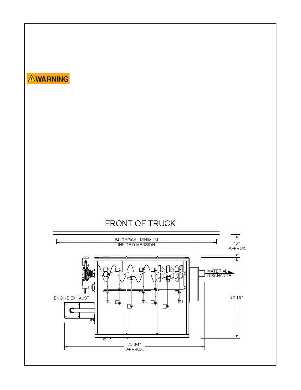
Machine Installaon
The size of the truck is dictated by the size of the machine, crew, and the how much insulaon the
installer wants to have available. Typically, this is a truck with an 8’ wide X 20’ long box (or longer) and
a gross vehicle weight rang (GVWR) of 21,000 lbs. The recommended minimum is a truck with a 7’ X
14’ box and a GVWR of 16,000 lbs. In addion, it should have two side doors and a full width rear door
for access and engine venlaon.
Tools and material needed for installaon:
• Drill and drill bits
• 3/8” bolts or lag screws
• Exhaust pipe ngs from the machine to underneath the truck (2 ½”)
• Fork li or other safe means to li the machine
• Pry bar(s)
• Screw driver, socket and ratchet, saw (hole or saber)

8
1. Move the machine into posion nong that you will need to have access to the rear and le side of
the machine. With the machine in posion; mark the truck oor where the engine exhaust (on the
le side) will go through the oor and mark the base’s mounng hole locaons.
2. The machine can be le in place or moved to provide beer access to the areas that need to be
drilled/cut. Using an 1/8” bit, drill pilot holes to determine if there is anything under the truck oor
that would interfere with the mounng fasteners or the engine exhaust pipe. If there is; move the
holes accordingly.
3. Cut a 3” hole in the oor for the exhaust pipe. Install the ashing (included), center it in the hole
and tack it down.
4. Drill holes for the machine mounng bolts. The size depends on what type and size of fasteners
you are using. Secure the machine to the truck oor.
5. The blower is at the back of the machine. Install the blower inlet screen into the elbow on the inlet
of the blower. The screen is shipped with the machine accessories.
The engine and engine exhaust piping could be extremely hot and could cause
burns. In addion; if ammable material comes in contact with these surfaces
it could ignite. Due to the variability of installaons Meyer cannot provide a guard for the engine
exhaust piping. The installer of the equipment must take the necessary steps to guard this surface from
contact.
6. Install the exhaust pipe and ngs (not included). Be sure to securely aach both ends of the
exhaust extension.
SECTION V
OPERATING INSTRUCTIONS
Before starng the machine check that no foreign material is in the hopper, that the
blowing hose is connected and the hose operator is in posion. Ensure that the only
people around the machine are those involved with its operaon.
Explosive fuel can cause res. Do not overll the fuel tank. Allow room for
expansion of the fuel. Fill the tank away from the engine and avoid spills. The
fuel tank must be in contact with the ground before and during lling. Do not let the fuel line come
in contact with the exhaust system. Fuel for this machine is highly ammable; failure to follow these
precauons could lead to a re and serious injury or death.
Engine exhaust contains carbon monoxide, a poisonous gas that will kill you in
minutes. You CANNOT see it, smell it, or taste it. Even if you do not smell exhaust
fumes, you could sll be exposed to carbon monoxide gas. If you start to feel sick, dizzy, or weak while
using this machine, shut it o and get to fresh air immediately. Seek medical aenon immediately.
You may have carbon monoxide poisoning.
The surfaces of the engine and exhaust can be extremely hot. Do not touch, allow to
cool before servicing.
Open all doors on the truck body/trailer and wait 10 minutes before starng engine.
This venlates fuel vapors and reduces the risk of res and explosions.

9
PRE-START CHECKS
1. The doors to the truck/trailer must be open so that the operator and machine have adequate
venlaon.
2. The blowing hose must be aached and the operator in posion.
3. Check that the switch on the Remote Control Cord is in the OFF posion. Connect the cord to the
control panel. Note: Starng the machine with the switch set to AIR or AIR/MATERIAL will overload
the clutch and the engine.
Do not operate the machine with any guards removed. The drive components
must be guarded before starng your machine and must remain guarded during
operaon. Failure to do so could lead to serious injury or death.
Do not reach into the hopper. There are moving parts in the hopper that can
crush and cut. Follow the machine safety shutdown instrucons before service or
maintenance.
MACHINE START UP INSTRUCTIONS
1. Read and understand the Operaon and Maintenance manual before starng the machine.
2. Doors to the truck/trailer must be open and no fuel vapor present.
3. Close the slide gate.
4. Set the Remote Control Switch to OFF.
5. Aach the fuel line to the engine and open the vent on the fuel tank.
6. Turn engine ignion key to ON. This powers the panel. Push green START buon. Buon will remain
lit.
7. Follow starng instrucons in engine Operator’s manual to start engine.
8. The engine speed is set via the throle lever. Move the lever to the “Fast” posion. Let the engine
warm up before operang the machine.
9. Open the slide gate and set it based on your blowing material.
MACHINE SHUTDOWN INSTRUCTIONS
1. Close the slide gate.
2. Set the Remote Control Switch to Air to clear the hose of material. When the hose is clear of
material, switch the Remote Control to OFF and disconnect it from the control panel.
3. Reduce the engine speed to idle. Let it run at idle to cool down before shung down.
4. Turn the engine ignion key to the OFF posion. Remove the key.
MACHINE SAFETY SHUTDOWN INSTRUCTIONS
1. Follow the MACHINE SHUTDOWN INSTRUCTIONS.
2. Disconnect the fuel tank and close the vent on the tank.
3. Disconnect the negave baery terminal and secure it using the lockout box.
4. Follow your employer’s Lockout/Tagout procedures.
Fire hazard. Whenever the machine is not in use or is being transported, disconnect
the fuel tank from the engine and close the vent on the fuel tank. Secure the tank
before transporng the machine.
10
SECTION VI
MAINTENANCE
Before performing any service or maintenance ensure that the machine cannot
be started. Follow machine safety shutdown instrucons before service or
maintenance. Failure to do so could lead to serious injury or death.
For engine service or maintenance see the engine Operator’s Manual.
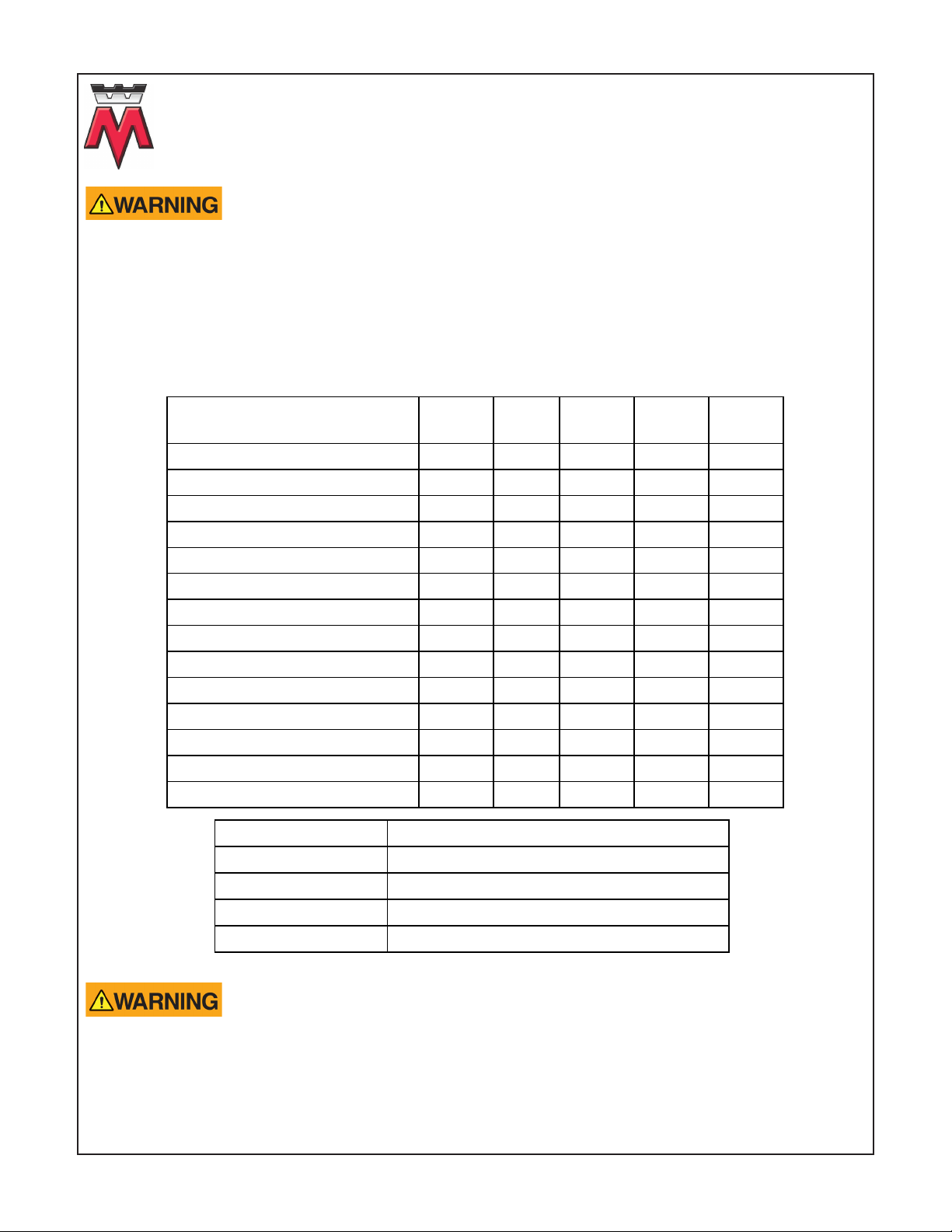
Your Meyer 551 Insulaon Blowing Machine is designed to be used with minimal maintenance for all
its components. The following is only a guide; experience is the best guide for the right maintenance
schedule for your machine.
DESCRIPTION
EACH
SHIFT
20
HOURS
100
HOURS
250
HOURS
500
HOURS
INSPECT ALL DRIVES X
CHECK GUARDS X
DRIVE ALIGNMENT & TENSION X
CHECK ENGINE EXHAUST PIPE X
GREASE BLOWER BEARINGS X
GREASE HOPPER BEARINGS X
CHANGE ENGINE OIL FILTER X
CHANGE BLOWER OIL X
CHANGE GEAR BOX OIL X
CLEAN INLET SCREEN X
CHANGE SEALSTRIPS X
OIL DRIVE CHAINS X
CHECK ALL DRIVE SET SCREWS X
ENGINE AIR FILTER X
ALL BEARINGS NLGI grade #2 LITHIUM GREASE
DRIVE CHAIN 30W NON DETERGENT MOTOR OIL
BLOWER OIL: AEON NLGI grade #2 LITHIUM GREASE
ENGINE SAE 10W30 MOTOR OIL
REDUCER GEARBOX AGMA #8 GEAR OIL
Removing guards exposes personnel to moving parts. Prior to removing any guards
the machine must be prevented from starng and the parts from moving. Remove
the key from the engine ignion, disconnect the fuel line, and disconnect the negave baery terminal
and secure it using the lockout box. Follow your employer’s Lockout/Tagout procedures.
Other manuals for 550 Series
1
Table of contents
Other Meyer Blower manuals


