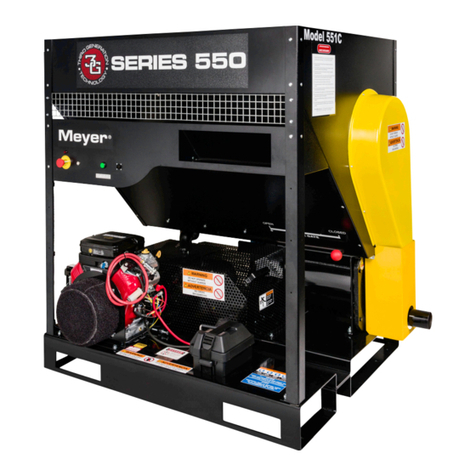
Meyer 550 Series Guide

1
292-K-003
Eecve 07-17-2023
Series 550
Meyer Insulaon Blower
INSTALLATION, OPERATION &
MAINTENANCE INSTRUCTIONS
Wm. W. Meyer & Sons, Inc.
1700 Franklin Blvd. • Libertyville, Illinois 60048-4407 • 847-918-0111 • Fax: 847-918-8183
email: sales@wmwmeyer.com ·meyercontractor.com or wmwmeyer.com
Read this manual carefully before installing, operang, or maintaining this equipment.
Failure to do so could result in serious injury or death.
Save this manual

2
TO THE OWNER, AND INSTALLATION, OPERATION AND MAINTENANCE PERSONNEL
The safety of the operator and those people that may come into contact with the equipment is of
great importance to Wm. W. Meyer & Sons, Inc. (“Meyer” “factory”). The decals, shields, guards,
and other protecve features designed, furnished, or recommended for this machine are there for
your protecon. This machine is designed for use with loose ll insulaon only. Other material could
cause serious injury and will void the warranty. The machine is powered by an internal combuson
engine which produces Carbon Monoxide Gas; it must be operated in a well-venlated area. BEFORE
aempng to operate or perform maintenance on this equipment READ carefully and UNDERSTAND all
safety instrucons contained in this set of Instrucons. Failure to do so could result in serious injury or
death.
Equipment owner responsibilies
Equipment owners are responsible for understanding the contents of this document and compliance
with applicable government laws and regulaons and appropriate industry standards. The owner
should also contact any associaons aliated with their market for any training, cercaon, and/
or proper procedures (suggested or required), for their parcular business. Appropriate safety and
equipment training is the responsibility of the owner. The owner/operator is responsible for any
hazards related to the material that is being handled by the machines and for ensuring that the users of
the equipment have and use the proper Personnel Protecve Equipment (PPE). In addion, the owner
must create a Lockout/ Tagout procedure for personnel to follow before performing any maintenance
on this equipment. This manual is intended to assist the owner in the creaon of safety procedures and
in the training process. The operaon and maintenance of this equipment should be restricted to those
trained in its use and possess the expert knowledge to perform maintenance.
TABLE OF CONTENTS
Safety Precauons ...................................................................................... 2
Applicaon and Models.............................................................................. 8
Receiving and Inspecon............................................................................ 8
Specicaons and Installaon .................................................................... 9
Machine Operang Instrucons ............................................................... 11
Maintenance............................................................................................. 12
Troubleshoong........................................................................................ 14
SECTION I
SAFETY PRECAUTIONS

3
Operaon and Maintenance personnel responsibilies
Personnel that are operang or maintaining this equipment must READ carefully and UNDERSTAND the
secons of this Instrucon Manual relevant to the work they are performing. The various precauons
and recommendaons detailed within this manual are not necessarily all-inclusive. These instrucons
are intended to provide general safety and operaonal guidance relang to typical uses with which
Meyer is familiar. If you have any safety or operaonal quesons pertaining to the design or applicaon
of the equipment, we encourage you to contact Meyer at (847) 918-0111.
SIGNAL WORD DEFINITIONS
Indicates a hazardous situaon which, if not avoided, will result in death or serious
injury.
Indicates a hazardous situaon which, if not avoided, could result in death or serious
injury.
Indicates a hazardous situaon which, if not avoided, could result in minor or
moderate injury.
Indicates informaon that is important, which if not followed, may cause damage to
the equipment.
IMPORTANT SAFETY INFORMATION
To reduce the risk of serious injury or death:
Be Qualied.
• Operaon of this equipment must be limited to those that are properly trained in its use.
• Servicing or maintaining this equipment must be performed by trained maintenance personnel
only.
Read all safety informaon.
• Obey all safety labels on the equipment. Do not remove any safety labels. If the equipment is
missing any labels (see “Safety Labeling” secon), contact Meyer immediately and before pung
the equipment into service.
• Read and understand all the safety related informaon contained in this manual and the Engine
manual prior to aempng to perform any work with or on this equipment.
Heavy - handle safely. The weight of this equipment and its component parts could cause serious injury
if dropped or mishandled during installaon, service, or maintenance. Always use safe handling and
rigging methods.
Operate in a well-venlated area. The carbon monoxide from the engine exhaust is an odorless,
colorless, poison gas. If inhaled can lead to carbon monoxide poisoning resulng in serious injury or
death.
When using the machine, make sure the truck or trailer is parked outside and never in a building or
garage.
Engine exhaust must be piped outside the machine trailer or truck and directed away from the interior.

4
Doors of the truck or trailer must be open during operaon to allow for the movement of outside air
through and to provide venlaon for the operator and the air-cooled engine.
Guard and avoid dangerous parts. There are moving parts of this equipment that will crush and
cut any body part that they contact, resulng in serious injury or death. Never operate the machine
without all guards properly installed.
Hopper Opening must only have material loaded into it. Hands, arms, and other body parts should
never enter the hopper opening.
Never open access covers/door or reach inside the equipment for any reason while it is in operaon.
Any accessory or auxiliary components installed with this equipment must have protecve guarding
correctly installed and permanently fastened in place.
Be Aware that the equipment can be started remotely, without warning.
Always have (1) person at the machine while it is running. They must be trained in its proper use, able
to maintain control over people interacng with the equipment, and be close enough to turn it o in
case of an emergency.
Never blow insulaon on or near sources of heat, ame, sparks, or stac discharge.
Follow Machine Safety Shutdown Instrucons before removing any guards, performing maintenance,
or making any adjustments, clearing material, invesgang a malfuncon, or cleaning the equipment.
Keep hands, feet, or other body parts, loose clothing, jewelry, etc., clear of the hopper inlet and
material discharge. Never disconnect the material hose while the machine is running or direct
discharged materials at others.
Lockout/Tagout all sources of energy before installing, servicing, or maintaining this equipment.
Potenal sources of energy include but are not limited to: motors, switches, cylinders, and solenoids.
Also consider:
• Equipment may start remotely, without warning, if energized.
• Hazardous voltage presents the risk of electrical shock.
• Equipment surfaces may be hot; allow them to cool before performing any work.
Secure the portable fuel tank before transporng the machine. In addion, the fuel tank must not be
stored in an enclosed container such as a truck body or trailer. Fuel vapors can build up leading to a
hazardous situaon.
Push the E-Stop buon if something unforeseen occurs. This will completely stop the machine and
illuminate the Red Panel Light. Before restarng the machine close the slide gate and turn the Remote
Control panel switch to “OFF”.
Wear the proper PPE (Personal Protecve Equipment) Personnel using the machine must always wear
appropriate clothing and equipment for the work environment as dened by local, state, and federal
safety requirements, including but not limited to:
• Hearing Protecon
• Eye Protecon (goggles or safety glasses)

5
• Breathing Protecon (respirator, lter mask)
• Skin Protecon (long sleeved shirts, pants, and gloves) or protecve suit
Contact the loose ll insulaon manufacturer for any addion PPE requirements.
HAZARD IDENTIFICATION
Principle of operaon
The insulaon blowing machines that Meyer & Sons manufacturers and sells are machines that have
rotang shas with paddles, pins and vanes designed to break up and move compressed material
(cellulose and berglass) from an open hopper into a pneumac conveying line. Once in that line or
hose, the material is propelled through the hose and exits into an open space (building ac) or an
enclosed space (sidewall). Because of the way in which material is loaded into the machine, the hopper
must be open and therefore moving parts are accessible. The machine likewise has moving drive train
components which must always remain guarded.
Amputaon hazard
The insulaon blowing machine shas are driven by an engine/motor at a relavely high speed. The
shas are connected to the engine or motor via roller chains or transmission belts. The spinning shas
and connected drive train components present a serious personal injury hazard, including but not
limited to amputaon. If any human body part comes in contact with these parts and an immovable
object, such as the machine hopper wall, that body part could be cut o.
Exposure to hazards
In order for the insulaon machine to funcon, material must be able to be placed in an open and
accessible hopper. It is designed such that material can be put into the hopper without personnel
coming into contact with rotang parts. The discharge of the machine is designed to have a hose
aached in order for the insulaon to be blown where it is required. The discharge of the hose must
never be covered by a human hand or other body part and must only be directed to areas where
it cannot come in contact with people and/or human body parts. The drive train components are
guarded and must remain so when the machine is in operaon. There are no adjustments that can be
made to the components while the machine is running.
Training
The owner bears the responsibility to ensure that personnel who may be working on/or operang
the insulaon machine are properly trained. Personnel must be aware that: (1) anything coming into
contact with the moving parts in the machine hopper could be cut o/amputated; (2) if body parts
come in contact with the rotang vanes in the feeder, they will be cut o/amputated; (3) before
working on, cleaning, repairing or maintaining a machine, Lockout/Tagout procedures must be strictly
followed; and (4) the machine must not be operated without guarding in place. Before interacng with
the insulaon machines, personnel must read the Operator’s Manual.

6
Safety Labels

7

8
The MEYER Model 551 INSULATION BLOWING MACHINE is designed to process and blow all of the
currently available loose-ll insulaons on the market today.
This equipment must be used only for the purpose for which it was intended. Any
other use could cause serious injury, costly damage to the equipment and will void
the warranty.
INFORMATION FOR SAFETY AND SERVICE
Type/Size___________________________________
Serial Number_______________________________
Date of Installaon___________________________
SECTION II
APPLICATION & MODELS
SECTION III
RECEIVING AND INSPECTION
Upon receipt of equipment and material from Meyer, the following basic steps should be taken. The
equipment is heavy and proper handling procedures should be used (See the "Heavy - handle safely"
informaon in the "IMPORTANT SAFETY INFORMATION" secon.)
1. Use the packing list to determine that all the items shipped have been received. Your equipment
was carefully crated for safe shipment when given to the carrier. If Items are missing, contact
Meyer per contact informaon at the end of this secon.
2. Check for damage. Damage in transit is the responsibility of the carrier. Title to your equipment
and all other items in the shipment were transferred to you as soon as the shipment le our dock,
thus it is your responsibility to handle any claim. In the event damage has occurred:
• Be sure to have the driver sign a copy of the freight bill with a notaon about any damage and
contact their oce before the driver leaves your premises.
• Contact the carrier to arrange for an independent inspector to come out to inspect the damage
and prepare the inspecon report. It is imperave that this inspecon is done before you start
to unpack or use any of the equipment.
• If there are any visible problems with your unit or any other items in the shipment, you or the
driver must note in detail the damage on all copies of the freight bill before signing for the
shipment. Then immediately call Meyer.
• Photographic records of the damage are helpful to communicate the extent and type of
damage as well as provide a clear record.

9
SECTION IV
SPECIFICATIONS AND INSTALLATION
• In addion to inspecng damaged equipment, you should also check the condion of the safety
labels to ensure they have not been damaged or come o. If they have, contact Meyer for
replacements prior to installaon.
• Concealed Damage: If Equipment or goods are discovered to be damaged in shipment at a later
date, contact the carrier and Meyer immediately.
• In all cases of damage in transit, contact Meyer for assistance in determining whether or not
this damage may, in any way, aect safety or proper operaon. Please contact us so that we
can assist you with replacement parts or with any quesons about the claim process, using the
following contact informaon:
Wm. W. Meyer & Sons, Inc.
1700 Franklin Blvd.
Libertyville, IL 60048
sales@wmwmeyer.com
847-918-0111
EQUIPMENT SPECIFICATIONS
WIDTH: 63”
DEPTH: 42 1/2”
HEIGHT: 59”
WEIGHT: APPROX. 1,100 LBS.
Machine Installaon
The size of the truck is dictated by the size of the machine, crew, and the number of bags of insulaon
transported. Typically, this is a truck with an 8’ wide X 20’ long box (or longer) and a gross vehicle
weight rang (GVWR) of 21,000 lbs. The recommended minimum is a truck with a 7’ X 14’ box and a
GVWR of 16,000 lbs. In addion, there should be a door on either side of the body and a full width rear
door. This is to provide: proper air ow to allow to aid in the removal of fuel vapors, venlaon for the
air-cooled engine, fresh air for the operator, and help prevent any buildup of dangerous engine exhaust.
Tools and material needed for installaon:
• Drill and drill bits
• 3/8” bolts or lag screws
• Exhaust pipe ngs from the machine to underneath the truck (2 ½” dia.)
• Forkli or other safe means to li the machine
• Pry bar(s)
• Screwdriver, socket and ratchet, saw (hole or saber)

10
1. Move the machine into posion nong that you will need to have access to the rear and le side of
the machine. With the machine in posion; mark the truck oor where the engine exhaust (on the
le side) will go through the oor and mark the base’s mounng hole locaons.
2. The machine can be le in place or moved to provide beer access to the areas that need to be
drilled/cut. Using an 1/8” bit, drill pilot holes to determine if there is anything under the truck oor
that would interfere with the mounng fasteners or the engine exhaust pipe. If there is; move the
holes accordingly.
3. Cut a 3” hole in the oor for the exhaust pipe. Install the ashing (included), center it in the hole
and tack it down.
4. Drill holes for the machine mounng bolts. The size depends on what type and size of fasteners
you are using. Secure the machine to the truck oor.
The engine and exhaust piping could be extremely hot and could cause burns or
ignite a re. Due to the variability of installaons, Meyer cannot provide a guard for
the engine exhaust piping. The installer of the equipment must take the necessary steps to guard this
surface against contact by people or ammable materials.
Engine exhaust piping must be routed away from the side doors to help prevent the
exhaust from entering the truck body or trailer. In addion, it should be routed away
from any ammable materials such as the truck fuel tanks. Ensure that the proper ngs and piping
are used and installed correctly. Failure to do so could lead to serious injury or death.
5. Install the exhaust pipe and ngs (not included). Be sure to securely aach both ends of the
exhaust extension.

11
SECTION V
MACHINE OPERATING INSTRUCTIONS
Prior to use, the operator must read and understand the enre manual and all the
safety related informaon including all the warnings and guarding instrucons. This
includes but is not limited to reading and understanding the “IMPORTANT SAFETY INFORMATION” and
“HAZARD IDENTIFICATION” Secons. Verify that all guarding is in place and the area is clear of all non-
essenal personnel. Failure to do so could lead to serious injury or death.
Engine exhaust contains carbon monoxide, a poisonous gas that will kill you in
minutes. You CANNOT see it, smell it or taste it. Even if you do not smell exhaust
fumes, you could sll be exposed to carbon monoxide gas. Operate only in well venlated areas. If you
start to feel sick, dizzy, or weak while using this machine, shut it o and get to fresh air immediately.
Seek medical aenon immediately. You may have carbon monoxide poisoning.
The surfaces of the engine and exhaust can be extremely hot. Do not touch or allow
anything to come in contact with the hot parts.
Venlate fuel vapors to reduce the risk of res and explosion. Open all doors on the
truck body/trailer and wait 10 minutes before starng the engine. Leave all doors
open throughout use.
FUEL SAFELY
Fuel is highly ammable. Avoid spills, heat, and buildup of stac electricity. Never fully ll the fuel
tank, allow room for the expansion of the fuel so that when it expands it does not overow. Fill the
tank away from the engine and other sources of heat or open ames. Always ll the tank on the
ground, never in the back of a truck or other vehicle. The tank must be in constant contact with the
ground and the pump nozzle must be in constant contact with the tank during the lling process. This
will lessen the chance of stac electricity buildup. Failure to follow these instrucons could lead to
serious injury or death.
PRE-START CHECKS
1. The operaon of this machine must be limited to people that have read and understood this
manual, the equipment labels, and the proper handling of the insulaon material being installed.
2. Only people involved in the machine operaon are in the vicinity.
3. Check that no foreign material is in the hopper.
4. The doors to the truck body / trailer must be open to provide adequate venlaon for operator and
machine.
5. Check that all guards are in place.
6. The blowing hose is aached to the machine and the person manning the hose is in posion.
7. Check that the switch on the Remote Control Cord is in the OFF posion and connected to the control
panel.
Starng the machine with Remote Control Cord Switch in either the AIR or AIR/
MATERIAL posion will overload the clutch and the engine.

12
SECTION VI
MAINTENANCE
MACHINE STARTUP INSTRUCTIONS
1. Doors to the truck/trailer must be open and no fuel vapor present.
2. Close the slide gate.
3. Set the Remote Control Switch to OFF.
4. Aach the fuel line to the engine and open the vent on the fuel tank.
5. Turn engine ignion key to ON. This powers the panel. Push green START buon. Buon will remain lit.
6. Follo
w starng instrucons in engine Operator’s Manual to start engine.
7. The engine speed is set via the throle lever. Move the lever to the “Fast” posion. Let the engine
warm up before operang the machine.
8. Open the slide gate and set it based on your blowing material.
MACHINE SHUTDOWN INSTRUCTIONS
1. Close the slide gate.
2. Set the Remote Control Switch to Air to clear the hose of material. When the hose is clear of
material, switch the Remote Control to OFF and disconnect it from the control panel.
3. Reduce the engine speed to idle. Let it run at idle to cool down before shung down.
4. Turn the engine ignion key to the OFF posion. Remove the key.
MACHINE SAFETY SHUTDOWN INSTRUCTIONS
Before removing guards, servicing, or performing maintenance, reaching into the hopper, making
adjustments, or clearing material jams:
1. Follow the MACHINE SHUTDOWN INSTRUCTIONS.
2. Disconnect the fuel tank and close the vent on the tank.
3. Disconnect the negave baery terminal and secure it using the lockout box.
Maintenance must be performed by qualied personnel possessing the appropriate expert knowledge
for the specic task.
Lockout/Tagout the machine before performing any service or maintenance
including removing any guards. Failure to do so could lead to serious injury or death.
For engine service or maintenance see the engine Operator’s Manual.
Your Meyer 551 Insulaon Blowing Machine is designed to be used with minimal maintenance for all
its components. The following is only a guide; experience is the best guide for the right maintenance
schedule for your machine.

13
DESCRIPTION
EACH
SHIFT
20
HOURS
100
HOURS
250
HOURS
500
HOURS
INSPECT ALL DRIVES X
CHECK GUARDS X
DRIVE ALIGNMENT & TENSION X
CHECK ENGINE EXHAUST PIPE X
GREASE BLOWER BEARINGS X
GREASE HOPPER BEARINGS X
CHANGE ENGINE OIL FILTER X
CHANGE BLOWER OIL X
CHANGE GEAR BOX OIL X
CLEAN INLET SCREEN X
CHANGE SEALSTRIPS X
OIL DRIVE CHAINS X
CHECK ALL DRIVE SET SCREWS X
ENGINE AIR FILTER X
ALL BEARINGS NLGI grade #2 LITHIUM GREASE
DRIVE CHAIN 30W NON DETERGENT MOTOR OIL
BLOWER OIL: AEON NLGI grade #2 LITHIUM GREASE
ENGINE SAE 10W30 MOTOR OIL
REDUCER GEARBOX AGMA #8 GEAR OIL
In order to perform any service or maintenance on the drive train the drive guards must be removed.
1. Follow the MACHINE SAFETY SHUTDOWN INSTRUCTIONS.
2. Remove the two bolts that hold the le and right side guards down.
3. Remove the le side guard rst and then the right side.
4. Replace the guards aer compleng the service or maintenance and before operaon.
When replacing or ghtening drive belts or chain it is imperave that the drive components –
sprockets or sheaves are in line with each other. Use a straight edge of sucient length to make the
determinaon.
Replace the drive belts if there are signs of cracking or wear. If belts are slipping or squealing during
operaon adjust them by moving the drive/driven components in the appropriate direcon to restore
proper tension.
Check the tension on the chain drives when they are lubricated. On the hopper chain drives if there is
more than 3/4” deecon or play measured equidistant between the sprockets, the chain needs to be
replaced. The feeder drive chain tension can be adjusted via the base mounted tensioner.

14
SECTION VII
TROUBLESHOOTING
Lockout/Tagout the machine before performing any service including removing
guards. Failure to do so could lead to serious injury or death.
Machine is running but no material is discharging from hose.
• Slide gate is in the closed posion.
• Clutch is in OFF posion.
• Feeder shear pin is broken.
• Remote Control wire or panel connector is broken or damaged.
• Remote Control wire board connecons loose.
• Faulty clutch relay on circuit board or faulty circuit board.
• Drive belt is slipping or broken.
• Feeder chain is o the sprocket or broken.
• Hopper chains are o their sprockets or broken.
• Material jam in machine or hose.
• Hose is bent or closed o from machine to ac.
• Worn out sealstrips in feeder allowing blowback.
Low material output.
• Check slide gate posion.
• Paral obstrucon in hopper or hose.
• Hose is kinked or damaged.
• Clutch is slipping.
• Machine speed is too low.
• Blower inlet is clogged.
• Blower outlet tubing to feeder has slipped o its connecon.
• Bleed valve assembly is in the open posion.
• Operator is overlling hopper resulng in material top pressure which can lead to material bridging
above the feed reel.
• Material is scking to agitator or feed reel from forcing too much material into the hopper, this
pracce causes less material to be conveyed through the system due to build up on surfaces.
Machine or engine seems sluggish while blowing material.
• Engine is overheang due to low RPM.
• Engine is overheang due to cooling shrouds clogged with insulaon.
• Material is wet inside hopper.

15
• Too much material forced into hopper.
• Clutch slipping during operaon.
• Too many hose reducons.
• Obstrucon at blower inlet.
• Drive belts may be slipping.
• Gear Box oil is low or empty.
• Loose drive components.
Engine runs but somemes misres while blowing material.
• Poor fuel in tank.
• Dirt or water in the fuel system.
• Spark plug wire is loose.
• Oil sentry wires connectors are loose.
• Loose wires or connecons at circuit board behind control panel.
• Faulty circuit board.
• Faulty engine ignion module.
• Engine overheang.
Unusual sounds coming from machine during operaon.
• High pitched squeal near perforated guards - Check for loose drive belts.
• Metal scraping sound when shung down machine - Clutch plate is rubbing.
• Banging sound from hopper area – Loose object has fallen into hopper.
• Constant air leaking sound while machine is in operaon – Bleed valve is open or loose tubing
between the blower and feeder.

SAFETY SUPPLEMENT
ATTENTION INSTALLERS/OPERATORS FOR YOUR
PROTECTION:
1. Read and understand the Operating Manual accompanying this
equipment before performing any work.
2. Additional safety label kits are available from Meyer upon request at no
charge. This is part of our effort to ensure this equipment is installed,
personnel that may ever be on-site that a potential for injury could occur.
3. Under no circumstances should this equipment be installed or operated
in a manner that permits access to the interior of the insulation blowing
machine.
4. Outlet connections must always have a hose attached.
5. Always power OFF the machine before performing any work.
6. Always keep loose clothing, hands, feet or any parts of your body, tools
and/or any foreign objects away from the interior of hopper and hose.
7. Never remove the discharge hose that is attached to the machine without
8. Consult the Meyer factory if you have any questions regarding the proper
installation, operation and maintenance of this equipment.
Wm. W. Meyer & Sons, Inc.
Website: http://www.meyerinsulation.com
File # 292-M-001
Eecve 1-4-2016

SAFETY LABELS
Locate all of the safety labels on your equipment and know their meaning before operating your
Insulation Blowing Machine.

NOTE: Contact Wm. W. Meyer & Sons, Inc. at 847-918-0111 for free replacement safety label kit.

SERIES 550 INSULATION BLOWING MACHINE
SAFETY PRECAUTIONS
Photos for reference only.
NEVER OPERATE THE MACHINE
WITHOUT HOSE ATTACHED TO THE
DISCHARGE TUBE
NEVER OPERATE THE MACHINE
WITHOUT GUARDS IN PLACE
292-M-001
Other manuals for 550 Series
1
Table of contents
Other Meyer Blower manuals
Popular Blower manuals by other brands

Ryobi
Ryobi RY09605 Replacement parts list

Stanley
Stanley STPT600 manual

Static Clean
Static Clean Sentinel BTI Installation operation & maintenance

Parkside
Parkside PKM 1500 A1 operating instructions

Utile
Utile LW401 Installation, operation & maintenance instructions

Ametek
Ametek EN858 Service and parts manual