Meyer E-58H User manual

FORM NO. 1-822
August 2005
Price: $4.25
E-58H, E-78 & E-88
power unit
service manual
Diamond Equipment
6 Angell Lane• Damariscotta, ME 04543-9720
Phone (207) 563-2227
www.diamondplow.com • email [email protected]
© 2005 Printed in the U.S.A.
Meyer Products LLC
18513 Euclid Ave. • Cleveland, OH 44112-1084
Phone (216) 486-1313
email•[email protected]
ELECTRO-LIFT

FOREWARD
This Service Manual includes complete information for servicing the following Electro Lift® Units:
E-58H
E-78 E-Z Mount Plus
E-88 E-Z Mount Xpress
IMPORTANT: Maintenance and repairs must be performed with the moldboard on the
ground.
The information is grouped according to the type of work being performed, such as diagnosis and testing,
disassembly and reassembly. Special tools and specifications are also included in this manual.
All information, illustrations and product descriptions contained in this manual are correct at
publication time. We do, however, reserve the right to make changes at any time without
prior notice.
MEYER PRODUCTS INC.
SECTION INDEX
Section Number Section Title ..................................................... Page
0 GENERAL INFORMATION AND
MAINTENANCE ....................................................... 1
1 GENERAL DESCRIPTION AND
THEORY OF OPERATION ...................................... 4
2 DIAGNOSIS ............................................................. 19
3 REPAIR PROCEDURE ............................................ 36
4 ELECTRONIC TROUBLESHOOTING ..................... 70
5 SPECIFICATIONS ................................................... 75
Meyer Products LLC reserves the right, under its continuing product improvement program, to change construction
or design details, specifications and prices without notice or without incurring any obligation.

SECTION 0 - GENERAL INFORMATION AND MAINTENANCE
CONTENTS
GENERAL INFORMATION .................................................... 2
• MODEL IDENTIFICATION .................................................... 2
• MODEL IDENTIFICATION AND
SERIAL NUMBER LOCATION ............................................. 2
• MOTOR IDENTIFICATION .................................................... 2
MAINTENANCE ..................................................................... 2
• GENERAL MAINTENANCE ................................................. 2
• CLEANLINESS ................................................................ 2
• VEHICLE ELECTRICAL SYSTEM ........................................... 2
• CHECK REGULARLY ......................................................... 2
POST-SEASON MAINTENANCE ....................................... 2
• MEYER HYDRAULIC FLUID M-1 ......................................... 2
• REPLACEMENT OF HYDRAULIC FLUID .................................. 3
• FILTERS ....................................................................... 3
• PROTECTION AGAINST RUST
AND CORROSION ........................................................... 3
-1-

Vehicle Electrical System
Maximum performance and efficiency of the Electro
Lift® unit requires that the vehicle’s electrical system
be properly maintained and consist of:
Battery -- ........ 70 Amp. Hr. Minimum or
550 Cold Cranking Amps.
Alternator ...... 60 Amp. Minimum
Check Regularly
1. Battery Terminals - Must be clean and free of
corrosion.
2. Electrical Connections - Must be free of corrosion
and tight.
3. Battery - Must be in first-class condition.
4. Alternator (or Generator) and Regulator - Must be
functioning to specifications.
5. Hydraulic Fluid Reservoir Level - A significant drop
in hydraulic fluid level indicates a leak which must
be located and corrected. Insufficient hydraulic
fluid may result in severe damage.
POST-SEASON MAINTENANCE
Meyer Hydraulic Fluid M-1.
Meyer Hydraulic Fluid M-1 is a specially formulated
mineral oil which maintains an almost constant
viscosity from normal to sub-zero temperatures.
Because it remains free flowing at extremely low
temperatures, the performance and efficiency are
not affected.
Meyer Hydraulic Fluid M-1 also contains an additive
which neutralizes moisture accumulating in the fluid
due to condensation. It is effective for a maximum of
one year’s use.
Meyer Products Inc. will not be liable for damages
resulting from the use of inferior or other fluids
or oils.
GENERAL INFORMATION
Model Identification
The E-58H, E-78 & E-88 unit is an electrically powered
hydraulic mechanism specifically designed for use with
the Meyer E-Z Mount Xpress and E-Z Mount Plus and
E-Z Mount Classic Snow Plow systems.
Model Identification and Serial Number Location
Inclusion of the model number and serial number is
extremely important when writing up warranty claim
forms and product report forms for proper evaluation
and follow up.
The basic model number is located on the name plate
(plastic cover). The serial number is located on the
name plate decal underneath the plastic cover.
MAINTENANCE
The following maintenance information is intended
as a basic guide for providing the E-58H, E-78 &
E-88 unit with the proper service and care. Sustained
heavy duty operation or operating under adverse
conditions may necessitate more frequent servicing.
General Maintenance
Cleanliness
The greatest enemy to any hydraulic system is dirt
or contamination. Therefore, cleanliness must be
stressed at the time of installation, servicing and
repairing.
-2-

Replacement of Hydraulic Fluid
After a season’s use, completely drain the hydraulic
fluid (including hydraulic fluid in hoses and cylinders).
Drain fluid through filler hole shown in Figure 0-1 or
drain hole in base by completely retracting lift rod
and unbolting unit to pour fluid out or using a suction
pump. Disconnect the fittings at the Angling and
Mount (E-88 only) cylinders and completely retract
the cylinder rods and purge cylinders and hoses of all
hydraulic fluid. Flush the complete system including
unit, hoses and angling rams with the M-2 Flushing
Fluid, or a non wax (Napthenic) cleaner. If kerosene
(Parrafinic) is used to flush the system, the system
must be flushed again to remove any kerosene with
M-2 Flushing Fluid, or a (Napthenic) based cleaner
that is wax free.
Refill E-58H, E-78 & E-88 unit with M-1 Fluid by fully
retracting lift rod (Ram) and filling reservoir to 1-1/2 “
below the filler hole. Fill and bleed hoses and Power
Angling and Mount (E-88 only) cylinders by loosening
hydraulic fittings at cylinders until they leak. Power
angle plow repeatedly from one side to the other
until fluid flows steadily from the leaking fittings while
maintaining a constant check on the reservoir fluid
level. Repeat for mounting (E-88 only) cylinder.
Raise and lower the plow several times and with lift
rod fully retracted, give a final check to the fluid level
and replace filler plug.
Filters
Clean the two filters located in base of unit and power
angling block with mineral spirits or equivalent and
blow out with compressed air. See Figure 0-1 for filter
locations.
Protection Against Rust and Corrosion
When the E-58H, E-78 & E-88 unit is not used for
extended periods, protect the chromed lift rod (Ram)
by fully extending it and coating it with chassis
lubricant. Full extension of the lift rod (Ram) fills the
cylinder with hydraulic fluid. Coat the exposed portions
of the Power Angling cylinder rods (Rams) and Mount
cylinder (E-88 only) of the E-Z Mount Xpress with
chassis lubricant to protect them against rust and
corrosion.
FIGURE 0-1 E-78
-3-
Drain Plug
Filler Plug
Filter Plugs
Lift Rod
Filler Plug
Drain Plug
Filter Plugs
FIGURE 0-1 E-88
Lift Rod

SECTION 1 - GENERAL DESCRIPTION AND THEORY OF OPERATION
CONTENTS
GENERAL DESCRIPTION ..................................................................................................... 5
THEORY OF OPERATION .................................................................................................... 5
• FUNCTIONS E-58H, E-78 & E-88 ................................................................................... 5
• ELECTRICAL AND FLOW CHARTS ........................................................................................ 6-15
•• E-88 ..................................................................................................................... 6-11
•• E-78 ...................................................................................................................... 12-15
•• E-58H ................................................................................................................... 31-35
ELECTRO LIFT® UNIT COMPONENTS .............................................................................. 16
• MOTORS ...................................................................................................................... 16
•• Iskra ..................................................................................................................... 16
• HYDRAULIC PUMP .......................................................................................................... 16
• PRESSURE RELIEF VALVE ................................................................................................. 16
• SOLENOID VALVES .......................................................................................................... 16-17
•• Cartridge ............................................................................................................ 16
•• Coil ...................................................................................................................... 17
“A” Solenoid Valve .............................................................................................. 17
“B” Solenoid Valve .............................................................................................. 17
“C” Solenoid Valve .............................................................................................. 17
“D” Solenoid Valve (E-88 only) ........................................................................... 17
“E” Solenoid Valve (E-88 only) ........................................................................... 17
• CHECK VALVES ............................................................................................................. 18
• PILOT CHECK VALVE ...................................................................................................... 18
• CROSSOVER RELIEF VALVES ............................................................................................. 18
• SOLENOID SWITCH ......................................................................................................... 18
• FILTERS ....................................................................................................................... 18
-4-

GENERAL DESCRIPTION
E-58H, E-78 & E-88 unit is an electrically powered and
electrically controlled hydraulic mechanism specifically
designed for use with Meyer Snow Plows. The E-88
and E-78 raises and lowers the plow with an integral
8” stroke hydraulic cylinder. The E-88 will also mount
and dismount the Xpress plow system from the vehicle
using a hydraulic Mount/Dismount Cylinder.
In addition to raising and lowering the plow hydraulically,
the E-58H, E-78 & E-88 angles the plow hydraulically,
left and right, via remote hydraulic cylinders.
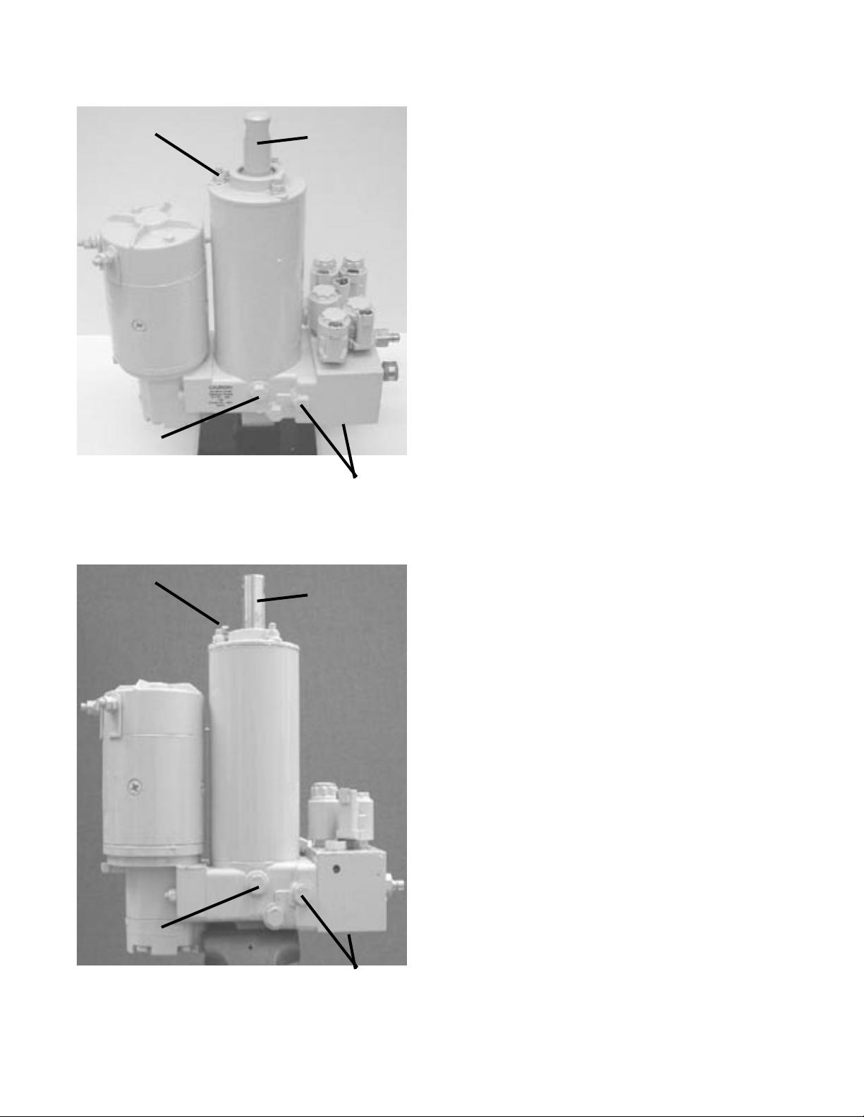
The Electro Lift® unit consists of a specially designed
high torque 12-volt DC motor which is directly coupled
to a gear-type hydraulic pump. The pump obtains its
supply of hydraulic fluid from an integral reservoir
which totally surrounds the integral hydraulic cylinder
which raises and lowers the plow.
The E-88 includes an integral valve body which
contains five electrically controlled solenoid valve
cartridges. Solenoid valve cartridge “A” which is
energized to allow the plow to lower by gravity.
Solenoid valve cartridge “B” is energized to route the
pressurized hydraulic fluid to the integral hydraulic
cylinder to raise the plow. Solenoid valve cartridge
“C” is energized to route the pressurized hydraulic
fluid to the left remote hydraulic cylinder to angle
the plow to the right. Solenoid valve cartridge “D” is
energized to route the pressurized hydraulic fluid to
the right remote hydraulic cylinder to angle the plow
to the left. Solenoid valve cartridge “E” is energized
to route the pressurized hydraulic fluid to extend the
mount/dismount hydraulic cylinder to remove the plow
from the vehicle. Mounting the plow to the vehicle only
requires energizing the electric motor since the normal
route for the pressurized hydraulic fluid is to retract the
mount hydraulic cylinder.
The E-58H & E-78 includes an integral valve body
which contains three electrically controlled solenoid
valve cartridges. Solenoid valve cartridge “A” which
is energized to allow the plow to lower by gravity.
Solenoid valve cartridge “B” is energized to route the
pressurized hydraulic fluid to the integral hydraulic
cylinder to raise the plow. Solenoid valve cartridge “C”
is energized to route the pressurized hydraulic fluid
to the left remote hydraulic cylinder to angle the plow
to the right. When all cartridge are not energized and
the motor is running the pressurized hydraulic fluid
will flow to the right remote hydraulic cylinder to angle
the plow to the left.
Additional components which control and supply
electrical current to the E-58H, E-78 & E-88 units are
an operator controlled Touchpad (E-58H only), RCM
(Remote Control Module); a solenoid switch to supply
high amperage current to the unit’s motor (motor
solenoid); a PCM (Plow Control Module) (E-78 & E-88
only)and a HCM (Headlight Control Module)(E-78 &
E-88 only). valve cartridge(s); and short heavy gauge
cables to distribute high amperage current directly
from the positive terminal of the vehicle’s battery and
ground the unit directly to the negative terminal of the
vehicle’s battery.
THEORY OF OPERATION
FUNCTIONS
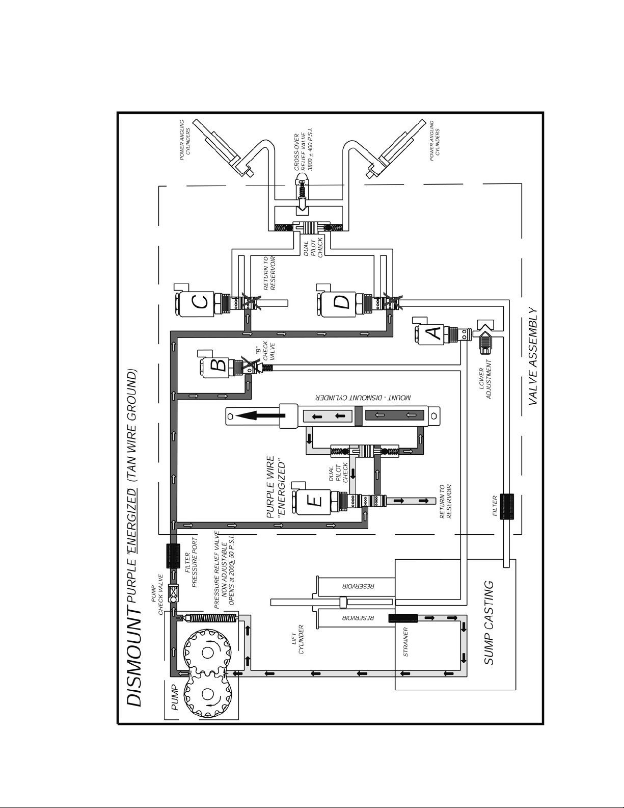
The E-88’s six basic functions performed are:
• Raise snow plow
• Lower snow plow
• Angle snow plow to right
• Angle snow plow to left
• Mount Xpress Snow Plow System
• Dis-mount Xpress Snow Plow System
Refer to Figures 1-1 through 1-6 (pages 6 thru 11) for
electrical and hydraulic flow chart for each function.
Each figure explains which component is actuated
and related in each function.
The E-58H & E-78’s four basic functions performed
are:
• Raise snow plow
• Lower snow plow
• Angle snow plow to right
• Angle snow plow to left
Refer to Figures 1-7 through 1-10 (pages 12 thru 15)
for electrical and hydraulic flow chart for each function.
Each figure explains which component is actuated and
related in each function.
-5-

E-88 Mount, Motor Only
-6-
FIGURE 1-1

E-88 Dismount, Motor and “E” Solenoid
-7-
FIGURE 1-2

E-88 Raise, Motor and “B” Solenoid
-8-
FIGURE 1-3

E-88 Lower, “A” Solenoid
-9-
FIGURE 1-4

E-88 Angle Left, Motor and “D” Solenoid
-10-
FIGURE 1-5

E-88 Angle Right, Motor and “C” Solenoid
-11-
FIGURE 1-6

E-58H & E-78 Raise, Motor and “B” Solenoid
-12-
FIGURE 1-7

E-58H & E-78 Lower, “A” Solenoid
-13-
FIGURE 1-8

E-58H & E-78 Angle Left, Motor only
-14-
FIGURE 1-9

E-58H & E-78 Angle Right, Motor and “C” Solenoid
-15-
FIGURE 1-10

Under a condition, such as when a hydraulic cylinder
is extended to the end of its stroke, eliminating
additional space for the pressurized hydraulic oil to
be pumped into, the alternate opening and closing
of the poppet valve controls the pump’s pressure
output and provides an escape for the pressurized
hydraulic fluid.
The pressure relief valve used in the E-58H, E-78 &
E-88 pump, while more sophisticated than the one
described, functions in the same manner. The pump
pressure relief valve may be adjusted to the specified
pressure of 2000 P.S.I. by adjusting the set screw after
installing a suitable pressure gauge of 2500 P.S.I. in
the circuit.
SOLENOID VALVES
Hydraulic valves are simple in concept and all have the
same basic function: Control the direction of oil flow.
Each Solenoid Valve consists of two components: the
Cartridge and the Coil.
Cartridge
The Cartridge consists of the hydraulic valve
mechanism and an armature which enables the
valve mechanism to be operated and controlled
electrically. The Cartridge is designed to screw in
and out of the E-58H, E-78 & E-88 units much like
the typical “spark plug”.
FIGURE 1-13
COIL
VALVE SPOOL
WI NDI NG
ARMATURE
FIGURE 1-11
ELECTRO LIFT® UNIT COMPONENTS
FIGURE 1-12
-16-
E-58H, E-78 & E-88 UNIT COMPONENTS
MOTOR (4-1/2”)
Iskra - Two terminal
The Iskra motor is a four pole, electromagnet motor
which consists primarily of a 4-1/2” diameter solid
steel frame, armature, brushes, field coils and pole
pieces. This motor can be used on vehicles with either
the common negative ground electrical system or the
positive ground electrical system.
HYDRAULIC PUMP
The pump in a hydraulic system employs an external
source of power to apply a force to a liquid. A pump
develops no power of its own. It simply transfers power
from an external source (the electric motor on the E-
58H, E-78 & E-88 unit) to the liquid in the hydraulic
system.
The basic operating principles of the hydraulic
pump used in the E-58H, E-78 & E-88 units are quite
simple. Figure 1-11 illustrates the basic components
of a positive displacement gear type pump and their
functions. The pumping action takes place within the
pump chamber which is connected to the reservoir by
the intake line. The pump chamber has an outlet line
in which the liquid under motion and pressure leaves
the pump to perform work.
PRESSURE RELIEF VALVE
A basic pressure relief valve is shown in
Figure 1-12. It consists of a poppet valve and a valve
spring. Both are located in a passage which connects
the inlet passage to the outlet passage. The poppet
valve is normally held closed by the valve spring,
sealing the connecting passage from the pressurized
outlet passage. The poppet valve, being a piston, is
exposed to the pressurized hydraulic fluid in the outlet
passage. Whenever the hydraulic pressure against
the poppet valve becomes greater than the pressure
being exerted on the poppet valve from the opposite
direction by the valve spring, the poppet valve will
open. This allows some of the pressurized hydraulic
fluid to flow through the connecting passage to the
non pressurized inlet passage. The effect is to lower
the pressure in the outlet passage which will allow the
valve spring to close the poppet valve again.

“C” Solenoid Valve E-88 only
The “C” Cartridge contains a spool valve when in the
energized position, the pressurized hydraulic fluid is
diverted to the left power angling cylinder, angling the
plow to the right. Also, the hydraulic fluid being forced
from the retracting right power angling cylinder flows
through the “D” Cartridge when de-energized back
to the reservoir.
“C” Solenoid Valve E-58H & E-78 only
The “C” Solenoid valve is used on the E-58H &
E-78 hydraulic unit for power angling. The “C”
Cartridge contains a spool valve whose static (de-
energized) position allows the pressurized hydraulic
fluid to flow to the right power angling cylinder which
angles the plow to the left. At the same time, it allows
the hydraulic fluid being forced from the retracting
left power angling cylinder to flow through the “C”
Cartridge back to the reservoir.
In the energized position, the pressurized hydraulic
fluid is diverted to the left power angling cylinder,
angling the plow to the right. Also, the hydraulic fluid
being forced from the retracting right power angling
cylinder flows through the “C” Cartridge back to the
reservoir.
“D” Solenoid Valve E-88 only
The “D” Cartridge contains a spool valve when in the
energized position, the pressurized hydraulic fluid is
diverted to the left power angling cylinder, angling the
plow to the right. Also, the hydraulic fluid being forced
from the retracting right power angling cylinder flows
through the “C” Cartridge when de-energized back
to the reservoir.
“E” Solenoid Valve E-88 Only
The “E” Solenoid valve is used on the E-88 E-Z Mount
Xpress for mounting and dismounting of the plow
from the vehicle. The “E” Cartridge contains a spool
valve whose static (de-energized) position allows the
pressurized hydraulic fluid to flow to the live end of the
mount cylinder which mounts the plow to the vehicle.
At the same time, it allows the hydraulic fluid being
forced from the dead end of the double acting mount/
dismount cylinder to flow through the “E” Cartridge
back to the reservoir.
In the energized position, the pressurized hydraulic
fluid is diverted to the to the dead end of the mount
cylinder which dismounts the plow from the vehicle.
At the same time, it allows the hydraulic fluid being
forced from the live end of the double acting mount/
dismount cylinder to flow through the “E” Cartridge
back to the reservoir.
-17-
ELECTRO LIFT® UNIT COMPONENTS CONT.
Coil
The Coil is the electrical component which operates
the Cartridge’s valve mechanism by producing
magnetism which pulls the Cartridge’s armature
toward it. Since the armature is connected to the
valve mechanism’s only moving part, it is pulled
by the armature.
Figure 1-13 illustrates the typical Coil. Whenever
electrical current flows to the Coil, it flows through
the winding, which consists of numerous turns
of copper wire. The flow of current through the
winding produces a magnetic field which pulls the
soft iron armature further into the Coil.
The armature pulls the valve spool or poppet
valve into its alternate (energized) position. Not
illustrated is an integral coil spring, which is
compressed when the armature is pulled by the
magnetism.
When the current flow ceases, the magnetic
field disappears and the compressed coil
spring pushes the armature back to its original
(de-energized) position.
“A” Solenoid Valve E-58H, E-78 & E-88
The “A” Cartridge contains a poppet valve whose
static or de-energized position is closed. Its energized
position is open.
The “A” Solenoid Valve retains hydraulic fluid in the lift
cylinder. It is energized (opened) to allow the hydraulic
fluid to flow from the lift cylinder back to the reservoir,
enabling the plow to lower by gravity.
The “A” Solenoid Valve is designed to remain
energized (open) while the plow is lowered, plowing
snow. This is the “float” feature which insures that the
plow maintains contact with the ground contour.
“B” Solenoid Valve E-58H, E-78 & E-88
The “B” Cartridge contains a poppet valve whose
static or de-energized position is closed. Its energized
position is open.
The “B” Cartridge contains a spool valve whose
(energized) position allows the pressurized hydraulic
fluid to flow to the lift cylinder, raising the plow.
The “B” Cartridge de-energized position retains the
hydraulic fluid in the lift cylinder, holding the plow
up.

SOLENOID SWITCH
The E-58H, E-78 & E-88 motor requires more current
or amperage to operate than the vehicle wiring, vehicle
ignition switch or toggle switches have the capacity to
handle. The solenoid switch is essentially a heavy duty
switch with the capacity to handle the heavy current
required by the motor. It is closed electrically by the
solenoid to convey the heavy current directly from the
vehicle battery via heavy gauge electrical cable. The
solenoid, which functions essentially the same as the
previously described solenoid valves, receives its low
amperage current at the proper times via the wiring
harness. This solenoid must be grounded to operate
properly.
FILTERS
Cleanliness is perhaps the single most important
ingredient in assuring a hydraulic system’s reliability.
Should the hydraulic fluid become contaminated,
malfunction and permanent damage to the hydraulic
system may occur. For this reason, all the E-58H,
E-78 & E-88 units are equipped with a filter system
consisting of:
• A fine screen strainer on the reservoir pump inlet.
•A high pressure filter on the pressure side of the
pump.
•A return filter on the power angling block leading
back to the reservoir..
With this system, the hydraulic fluid is filtered as it
leaves the reservoir on its way to the pump and on
the Power Angling units filtered again as it leaves the
pump. Because clean hydraulic fluid is most important
to insure Solenoid Valve reliability, the hydraulic fluid
leaving all cylinders is filtered before passing returning
to the reservoir. The filter screen, high pressure and
return filter are easily removed for periodic cleaning
or replacement.
IMPORTANT:
Should the hydraulic fluid become contaminated, it
will be necessary to replace all the hydraulic oil in the
system. The complete system (hydraulic unit, power
angling cylinders, mount cylinder and hoses) should
be flushed. Flush the system with Meyer Hydra-Flush™
Fluid M-2.
ELECTRO LIFT® UNIT COMPONENTS CONT.
CHECK VALVES
Check valves are very simple devices that have two
basic functions: They prevent fluid from passing
through them in one direction, but they allow fluid to
pass through them in the opposite direction.
In the E-58H, E-78 & E-88 a pump check valve is used
to prevent hydraulic fluid from leaking back through
the pump to the reservoir.
The E-58H, E-78 & E-88 unit uses one check valve
located between the “B” Solenoid Valve and the lift
cylinder. It prevents the hydraulic fluid in the lift cylinder
from leaking back through the “B” Solenoid Valve
which could cause the plow to drift down.
DOUBLE ACTING PILOT CHECK VALVE
The pilot check valve is more sophisticated in that
it incorporates a piston in addition to the ball, seat
and spring. It is located between the “C” and “D”
Solenoid Valves on the E-88 and next to the “C”
valve on the E-58H & E-78. It has two functions: The
first is to prevent the hydraulic fluid in either power
angling cylinder from leaking back to the reservoir.
The second is to allow the hydraulic fluid from the
retracting power angling cylinder during the angling
cycle to return to the reservoir. This is accomplished
by the pressurized hydraulic fluid moving the piston
which forces the check ball off its seat. The E-88 also
uses an additional pilot check valve located next to
the “E” valve. This allows the “E” valve to control the
mount/dismount function.
CROSSOVER RELIEF VALVE
When plowing snow, a snow plow can be exposed
to damaging forces caused by impact with hidden
obstructions, ends of curbs, etc. With power angling,
these damaging forces can damage not only the snow
plow but also the vehicle. The crossover relief valve
has the function of protecting the snow plow system
against these damaging forces under normal snow
plowing conditions. The crossover relief valve, cannot
protect the system from damaging forces that are too
great due to abusive snow plowing conditions.
Basically, the crossover relief valve functions
exactly like the previously described pump relief
valve. It’s designed to open at a specific pressure.
In this instance, the pressure is not produced by
the pump but rather by the damaging force. As an
example, assume that the right corner of the plow
runs into the end of a curb. The impact will attempt to
collapse the right power angling cylinder. As a result,
very high hydraulic pressure is produced within the
cylinder. When the produced pressure is high enough,
it opens the crossover relief valve, allowing the highly
pressurized hydraulic fluid to flow directly to the left
power angling cylinder.
-18-
When the crossover relief valve functions in this
manner, the excessive pressure is released, the
excessive energy produced by the impact is absorbed,
and the result is only a change in angled position of
the plow.
The crossover relief valve is factory set to the specified
pressure of 3800 P.S.I. ± 400 this setting is non-
adjustable.
Other manuals for E-58H
2
This manual suits for next models
2
Table of contents
Other Meyer Portable Generator manuals
Popular Portable Generator manuals by other brands

Winco
Winco EC18000VE/D Installation and operator's manual

Beckhoff
Beckhoff EK1914 operating manual

JYE Tech
JYE Tech FG085 Function Generator Quick use guide

Briggs & Stratton
Briggs & Stratton 1653 owner's manual

Agilent Technologies
Agilent Technologies ESG series quick start guide

Xantrex
Xantrex XPower 300 owner's guide