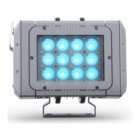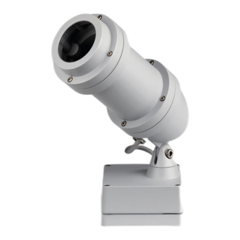
Luminaire with high performanc LED module
MOUNTING INSTRUCTIONS
The light source contained in this
luminaire and a damaged external flexible
cable or cord of this luminaire shall be exclusively
replaced by the manufacturer or his service agent
or a similar qualified person in order to avoid a
hazard. Mains M20 cable gland that accept cable
diameters from 8 mm to 15 mm. The power supply
cable may only be connected to a connection box
wich has the correct degree of protection and
safety class.
The DALI control wire is equipped with basic
insulation against the power supply cables.
and arrange electrical connection by plug
4
Connect light fitting in compliance with the
prevailing regulations in your country.
Luminaire for non-protected outdoor installation.
Luminaire is suitable for installation on normal
inflammable surfaces.
Disconnect from power supply before
opening the light fitting.
When installed at more than 3 metres height,
be sure to use at least 2 fixing screws.
Remove back part by loosening the 4 screws.
Tighten cable
gland. Make sure that the power supply cable sits
properly in the gasket. Set Back part on again
.
Then back part is to be screwed properly.
Remove complete luminaire front
(Tube+frame with glass) from housing.
Removing Gobo carrier module
by releasing the three setscrews ;
remove clip , insert colour filter and/or gobo
into the gobo carrier and clamp it into place
using the wire clips.
When using a metal gobo AND colour filter,
always insert the metal gobo first.
When loosening the screws care must be taken to
ensure that no parts of the luminaire fall down.
Insert the power supply cable through the cable
gland, Take care to use the correct gasket to suit
the diameter of cable being used. Set of gaskets
supplied with luminaire. Take the sheathing off the
last 6 cm of cable, shorten the individual wires N,
L and Dali to 2 cm. The sheathing of the cable
must be firmly clamped under the strain relief .
Make electrical connection.
Figure shows the equipotential connection. To
protect the LED against possible electrical surge, it
is imperative that the equipotential connector is
connected to the the earth potential.
To adjust the Gobo release one of the three set
screws and tighten again after focusing.
B
B
B
Insert of Gobo
A
C
E
F
C
5
5
E
159 0120 - 0117
Anbauleuchte mit Hochleistungs LED Modul
MONTAGEHINWEISE
Anschluß der Leuchte nach VDE 0100.
Anbauleuchte für ungeschützte Anlagen.
Leuchte ist geeignet für Montage auf
normal entflammbaren Baustoffen.
Vor dem Öffnen der Leuchte Netzspannung
trennen. Leuchte am Montageort befestigen.
Bei Montagehöhen über 3 m mindestens zwei
Befestigungsschrauben verwenden. Rückteil
durch Lösen der vier Schrauben abnehmen.
Auf richtigen Sitz
der elektrischen Zuleitung in den Dichtungen
achten.
Gobohalter durch Lösen der drei Gewindestifte
entnehmen, Klammer entfernen, passendes
Gobo
und mit Klammer befestigen.
Gobohalter mit
den drei Gewindestiften befestigen.
B
E
F
Die in dieser Leuchte eingebaute
Lichtquelle darf nur durch den
Hersteller oder seinen Kundendienst oder eine
ähnlich qualifizierte Person ersetzt werden. Zum
Anschluss der Leuchten Kabel mit Durchmesser
8-15 mm verwenden. Bei Leuchten mit
Anschlusskabel darf dieses nur in einen Anschluss-
kasten mit entsprechender Schutzart und Schutz-
klasse angeschlossen werden. Zur Vermeidung von
Gefährdungen darf eine beschädigte äußere
flexible Leitung dieser Leuchte ausschließlich vom
Hersteller, seinem Service- vertreter oder einer
vergleichbaren Fachkraft ausgetauscht werden.
Netzanschlußleitung durch die Kabelverschraubung
führen, dabei passenden Dichtungssatz
(Lieferumfang) wählen. Leitung 6 cm abmanteln,
Einzeladern und Dali auf 2 cm kürzen. Mantel
der Zuleitung muß unter der Zugentlastung
geklemmt werden. Die Dali-Steuerleitung ist
gegenüber der Netzleitung basisisoliert.
Elektrischen Anschluss vornehmen.
Abb. zeigt den Equipotential-Anschluss. Als
Schutz der LED vor möglicher Überspannung ist
der Äquipotential- Anschluss zwingend mit dem
Erdpotential zu verbinden.
Kabelverschraubung festdrehen.
Rückteil wieder aufsetzen, dabei die
elektrische Verbindung durch Steckverbinder
herstellen. Rückteil dicht verschrauben.
Komplettes Leuchten-Vorderteil
(Rohr + Rahmen mit Glas) vom Gehäuse nehmen.
oder Farbscheiben in den Gobohalter
einlegen
Beim Einsatz von Metallgobos + Farbfilter immer
das Metallgobo zuerst einlegen.
Zum Ausrichten des Gobos einen der drei
Gewindestifte leicht lösen und nach dem
Ausrichten wieder festschrauben.
N,L
5
4
5
B
B
Einsetzen eines Gobos
A
C
C
E
Beim
Lösen der Schrauben müssen die Bauteile der
Leuchte gegen Herabfallen gesichert werden!
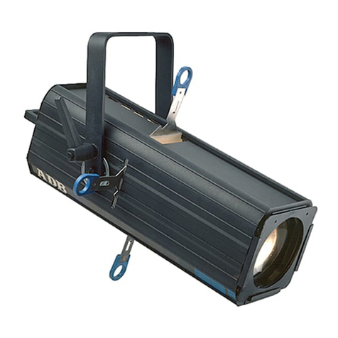
Nightspot B LED
Goboscheinwerfer
Gobo Projector
DALI
8 987 0.. 6..
8 987 2.. 6..
Schutzart - Protection IP 67
Schutzklasse - Safety Class II
MONTAGE
ANLEITUNG
Mounting
instructions
LICHTTECHNISCHE SPEZIALFABRIK
WILLY MEYER & SOHN GMBH & CO.KG
.
Stemmessiepener Weg 5 D-58675 Hemer
Leuchte mit Bügel:
H
H
Gelenkschraube mit 20 Nm festziehen.
ighten the screw with 20 Nm.
Luminaire with bracket:
T
8 987 0..
H
240
300
320
110
50
425
25°
90°
70
9
22
ADCB
CE
F
G
5
4
The luminaire should be positioned
so that prolonged staring into the luminaire
at a distance closer than 4,6 m is not
expected.
Do not stare at the light source.
Nicht in die Lichtquelle schauen !
Die Leuchte sollte so positioniert
werden, dass ein längeres Starren in die
Leuchte in einem Abstand näher als 4,6 m
nicht zu erwarten ist.
