mfh systems E-NERGY CARBON Series Parts list manual

E-NERGY CARBON
Electric surface heating system
Installation instructions & operating manual
Power supply unit BASIC TT
mfh systems
modern floor heating
mfh systems
modern floor heating

02
INSTALLATION SKETCH:
Heating foil Control unit Thermo sensor Transformer
Please keep this document in a safe place

03
Installation instructions & operating manual
E-NERGY CARBON
Table of contents
0. Installation sketch .......................................................................................................... 02
1. Delivery condition .......................................................................................................... 04
1.1. Scope of delivery............................................................................................................ 04
2. Information for users ..................................................................................................... 04
2.1. Safety Instructions ......................................................................................................... 04
2.2. General information ...................................................................................................... 05
2.3. Function and application ............................................................................................... 06
2.4. Operation....................................................................................................................... 06
2.5. Maintenance .................................................................................................................. 06
3. Installation of heating foils ............................................................................................ 06
3.1. Preparation .................................................................................................................... 06
3.2. Installation..................................................................................................................... 07
3.2.1. Pretreatment of the substrate ........................................................................................ 08
3.2.2. Thermal insulation ......................................................................................................... 08
3.2.3. Installation methods ...................................................................................................... 09
3.2.4. Installation under tiles ................................................................................................... 09
3.2.5. Ceiling installation ......................................................................................................... 10
3.2.6. Use in humid/wet rooms ................................................................................................ 10
4. Electrical connection ...................................................................................................... 10
4.1. Overview power supply of E-NERGY CARBON............................................................... 11
4.2. Installation of transformer ............................................................................................. 12
4.3. Connection of mains voltage and room thermostat....................................................... 13
4.4. Heating circuit connection.............................................................................................. 16
4.5. Electrical commissioning................................................................................................ 17
5. Commissioning .............................................................................................................. 17
6. Fault diagnosis ............................................................................................................... 17
7. Technical data ................................................................................................................ 18
8. Resistance values as a function of length ...................................................................... 20
9. Warranty and guarante .................................................................................................. 24
10. EC Declaration of Conformity......................................................................................... 28

04
1. Delivery condition
The E-NERGY CARBON panel heating system can be used as a full heating system, auxiliary heating or for
surface tempering can be used in the renovation (e.g. mould prevention).
1.1 Scope of delivery
• E-NERGY CARBON power supply unit BASIC TT
• Installation instructions & operating manual
The following additional products are required for the complete E-NERGY CARBON system:
• Assembled heating foils from 60 to 290 W/m²
• E-NERGY CARBON room thermostat
2. Information for users
Please read these operating instructions carefully before installation and follow the instructions. The E-NERGY
CARBON system can be used by children aged 8 years and older and by persons with reduced physical, sensory or
mental abilities or lack of experience and knowledge, if have been supervised or instructed in the safe use of the
device and the resulting understand the resulting dangers. Children must not play with the device. Cleaning and
user maintenance must not be carried out by children without supervision.
A copy of the operating instructions must be kept in the circuit distribution box. In case of change of ownership the
Please inform the subsequent owner about the installation. In humid/wet rooms DIN VDE 0100 part 701
be taken into account. If the E-NERGY CARBON heating foil is installed under e.g. a tiled floor (preferably
underneath the sealing) in a humid/wet area (e.g. shower), this area does not count as protection area 0, 1 or 2
according to DIN VDE 0100 part 701. Installation is permitted under these conditions.
2.1 Safety instructions
• Please read this manual carefully and completely before you start the installation.
• Transport: To protect all parts from damage, they should remain in their original packaging until they reach the
installation site. Internal parts can be damaged by shock and fall.
• Damaged equipment or parts must not be put into operation.
• Do not remove the safety labels and type plates.
• The individual components may only be installed in closed rooms.
• All assembly and installation work must always be carried out in a de-energised state.
• he circuit for connecting the power supply unit must be sufficiently dimensioned and fused for installation.
When operating the heating system, this circuit must not be overloaded.
• The device is not ready for operation when delivered and must first be connected by a qualified electrician.

05
Material Thickness
[mm]
Thermal conductivity
λ[W/(mk)]
Thermal resistance
Rλ[m2K/W]
Ceramic tiles 13 1,05 0,012
Natural stone tiles 12 1,2 0,010
Carpet – – 0,07 - 0,17
Disadvantage fleece 6,5 0,54 0,12
Linoleum 2,5 0,17 0,015
PVC flooring 2,0 0,20 0,010
Real wood parquet 11 - 14 0,09 - 0,12 0,055 - 0,076
Laminate 9 0,17 0,05
Cork-cork laminate 3 - 10 0,12 - 0,10 0,027 - 0,102
• Screw heads / washers must have a minimum diameter of 15 mm so that the fixing holes are sufficiently
covered.
• Protect the unit from moisture, heavy dust, aggressive liquids and vapours.
• Always ensure sufficient heat dissipation (distance to thermal insulation) and ventilation.
• Never connect several units in parallel on the output side.
• Compare all technical data of the products used. These must match or be within the specified range.
The power rating specified on the transformer must not be exceeded.
• Not suitable for children and persons with physically and/or psychologically limited abilities.
2.2 General information
The E-NERGY CARBON system is tested for safety. When working on the heating system, the operating instructions
must be handed over to the installer for information. The E-NERGY CARBON system can be installed inconspicuously
in ceilings, walls or floors. For installation, an installation plan must be drawn up to locate and position the heating
foils, power supply units, electrical supply lines and, if necessary, the temperature sensor (see sketch 3.1). In order to
ensure the optimum functionality of the system, qualified dimensioning and planning (e.g. heating load calculation
DIN EN 12831) is recommended. In the case of wall or floor surfaces, care must be taken to ensure that the heating
surfaces are not misaligned. In this case, check the corresponding product labelling (manufacturer‘s approval for elec-
tric panel heating) and observe the thickness and thermal conductivity λ[W/(mK)] or the resulting thermal resistance
Rλ[m2K/W]. The maximum thermal resistance of the floor covering, including the underlay belonging to the floor
covering, must not exceed the value of Rλ= 0.15 m2K/W.
Optimum and rapid heat distribution is achieved with very thin coverings (wallpaper, plaster systems, ceramic
coverings).
Planning guidelines for floor coverings on underfloor heating.

06
The system is operated with safety extra-low voltage 36V and thus offers a maximum of electrical safety. The
connection of the power supply unit to the house mains, as well as the installation of the temperature controller
and the electrical connection of the heating foils may only be carried out by a qualified electrician.
2.3 Function and application
The E-NERGY CARBON system is a foil heating system for walls, ceilings and floors that is optimised for radiant
heat. It is characterised by a very low installation height and ensures extremely rapid heating of individual areas
directly on the surface. It can be used in the most diverse areas, e.g. in living rooms, loft conversions, fitness and
sauna areas, conservatories, seating areas, mould prevention etc. Application.
In general with radiant heating systems, it makes sense to control the actual surface temperature of the heating
element by means of a temperature controller with a thermosensor. Use one controller per room and, for floor
installation, additionally one temperature sensor to detect and limit the surface temperature at the heating surface.
The heating foil is generally suitable for the subsequent insertion of holes with a maximum size of 70 mm (see
sketch under 3.1). Also observe the minimum distance of 50 mm between the holes (max. 5 cut-outs per 1 m) and
20 mm to the copper conductors (see 3.1). The copper strip on the heating track must not be damaged or cut.
2.4 Operation
The E-NERGY CARBON system impresses with its easy installation and operation.
To achieve the comfortable temperature, the controller is set to the desired value. The
Room temperature control is then automatic. The actual surface temperature, or heating-up
The maximum speed of the heating surfaces depends on the respective covering and the thermal insulation of the
substrate and can deviate from the set room temperature.
When selecting the room thermostats, the specifications of the Ecodesign Directive 2009/125/EC must be observed.
All E-NERGY CARBON room thermostats comply with the Ecodesign Directive 2009/125/EC
2.5 Maintenance
The E-NERGY CARBON heating system is maintenance-free. In the event of a malfunction, the following steps can
help:
•Please check the temperature controller, e.g. the fault indication on the display.
•Check the fuse on the power supply unit.
•
Check the fuse of the power supply and the in-house fuses or the earth-leakage circuit breaker.
If the fault remains unchanged, notify an authorised electrician or your specialist dealer. In general, it is recommen-
ded that the system be checked by an approved electrician after five years.
3. Installation of heating foils
3.1. Preparation
The E-NERGY CARBON systems are suitable for indoor use on ceilings, walls and floors.The selection of the
heating surface to be used depends on the later intended storage space for furniture and coverings as well as an
optimal heat input. Please refer once again to point 2.2 of the operating instructions.

7
3.2 Verlegung
Dieser Abschnitt bezieht sich auf die Verlegung der Folie und des Trafos.
Die Verlegung der Leitungen und der elektrischen Anschlüsse ist im Ab-
schnitt 3.3 Elektrischer Anschluss erklärt. Berücksichtigen Sie die Min-
destverarbeitungstemperatur von +5°C.
Bei Wänden unterhalb von 2,3 m Höhe und in Decken, die weniger als
45° zur Senkrechten geneigt sind, sollte die Heizfolie ca. 15 cm kürzer als
die Länge der Montagefläche sein. Die Heizfolie kann bei Bedarf senk-
recht zu den Kupferbahnen einmalig geteilt werden. Beschnitte immer
nur von der unkontaktierten Seite der Heizfolie vornehmen.
Jede andere unsachgemäße Beschädigung der Folie wie z. B. Einrisse
durch scharfe Gegenstände oder Knicke sind zu vermeiden. Bewahren Sie
die Heizfolie deshalb bis zum Einbau im gerollten Zustand in der Verpa-
ckung auf (Mindestbiegeradius beachten, siehe 4. TECHNISCHE DATEN).
Nach erfolgter Verlegung können jedoch Löcher, wie in Abschnitt 2.2
Funktion und Anwendung beschrieben, eingebracht werden.
Warnhinweis:
Beachten Sie, dass Schrauben nur dann in die Heizfläche eingebracht
werden dürfen, wenn diese mit Kunststoffdübeln zur elektrischen Isolati-
on installiert werden. Zusätzlich dürfen zwei Schrauben nicht mit einem
elektrisch leitfähigen Material (z.B. Metallbilderrahmen, Metallzierleiste,
Regalsystem aus Metall) verbunden werden. Verwenden Sie keine Nägel.
3.2.1 Vorbehandlung des Untergrunds
Die Heizfolie kann auf jedem tragfähigen, sauberen und ebenen Unter-
grund aus anorganischen Materialien wie Stein, Estrich, Putz, etc. oder
organischen Materialien wie Holz, Kork, Kunststoff (evtl. mit Oberflä-
chengrundierung / Haftvermittler), etc. angebracht werden. Die Un-
ter- und Deckschichtmaterialien müssen bis 70 °C temperaturbeständig
sein. Im Zweifel kontaktieren Sie den Hersteller dieser Materialien.
Unregelmäßige Oberflächen sind zu vermeiden (z.B. sichtbare Holz/
Stein - Ausmauerungen). Unter Umständen ist die Fläche vorab mit Aus-
gleichsputz oder Nivelliermasse auszugleichen.
Es ist besonders darauf zu achten, dass keine spitzen Erhebungen wie
Steine, Schraubenköpfe, Nägel oder ähnliches aus dem Untergrund her-
vorstehen.
3.2 Installation
This section relates to installation of the film and the transformer. Ins-
tallation of the supply lines and the electrical connections is explained
in Section 3.3 Electrical connection. Note that the minimum processing
temperature is +5 °C.
When walls are less than 2.3 m high and ceilings slope less than 45°, the
heating film should be about 15 cm shorter than the length of the ins-
tallation area. If necessary, the heating film can be divided once at right
angles to the copper conductors. Make sure that cutting is always from
the uncontacted side of the heating film.
All other inappropriate damage to the film, such as tears caused by
sharp objects or kinks, must be avoided. It is therefore important to keep
the heating film rolled up in its packaging until it is required for installa-
tion (note the minimum bending radius, see 4. TECHNICAL DATA).
After installation has been completed, holes may, however, be made in
the film, as outlined in Section 2.2 Function and use.
Warning:
Note that screws may only be fitted in the heating surface if they are in-
stalled with plastic plugs for electrical insulation purposes. In addition
to this, two screws may not be connected by a material that conducts
electricity (e.g. metal picture frames, decorative metal trim, metal shel-
ving system). Do not use any nails.
3.2.1 Preparation of the substructure
The heating film can be applied to any viable, clean and flat substructure
made from inorganic materials like stone, screed, plaster etc. or organic
materials like wood, cork, plastic (possibly with surface finishing / a tie la
yer) etc. The substrate and top layer materials must resist temperatures
of up to 70°C. Contact the manufacturer of these materials if you are in
any doubt.
Irregular surfaces must be avoided (e.g. visible wood/stone – brickwork).
Under certain circumstances, the surface may need to be evened out be-
forehand with plaster or a levelling compound.
Particular care must be taken to make sure that no pointed objects like
stones, screw heads, nails etc. are projecting out of the substructure.
07
The E-NERGY CARBON heating foil is not designed for installation as a storage heating system and therefore
cannot be used for installation within the floor screed. The closer the heating foil is installed to the surface of the
room, the faster the heating system reacts and emits the pleasant heat radiation into the room.
To facilitate your personal planning and documentation of the installation work, you should use the installation sketch
(page 2). Heating foils with contacts on both sides can be shortened into two individual foils at a later date. If heating
foils contacted on both sides are to be used over their entire length, the contacts at one end of the foil must be remo-
ved (see sketch 3.1). The foil must always be contacted electrically at the pre-assembled contacts.
General wall construction Foil trimming Foil savings
min. 50 mm | max. 5 recesses per 1 m
7
3.2 Verlegung
Dieser Abschnitt bezieht sich auf die Verlegung der Folie und des Trafos.
Die Verlegung der Leitungen und der elektrischen Anschlüsse ist im Ab-
schnitt 3.3 Elektrischer Anschluss erklärt. Berücksichtigen Sie die Min-
destverarbeitungstemperatur von +5°C.
Bei Wänden unterhalb von 2,3 m Höhe und in Decken, die weniger als
45° zur Senkrechten geneigt sind, sollte die Heizfolie ca. 15 cm kürzer als
die Länge der Montagefläche sein. Die Heizfolie kann bei Bedarf senk-
recht zu den Kupferbahnen einmalig geteilt werden. Beschnitte immer
nur von der unkontaktierten Seite der Heizfolie vornehmen.
Jede andere unsachgemäße Beschädigung der Folie wie z. B. Einrisse
durch scharfe Gegenstände oder Knicke sind zu vermeiden. Bewahren Sie
die Heizfolie deshalb bis zum Einbau im gerollten Zustand in der Verpa-
ckung auf (Mindestbiegeradius beachten, siehe 4. TECHNISCHE DATEN).
Nach erfolgter Verlegung können jedoch Löcher, wie in Abschnitt 2.2
Funktion und Anwendung beschrieben, eingebracht werden.
Warnhinweis:
Beachten Sie, dass Schrauben nur dann in die Heizfläche eingebracht
werden dürfen, wenn diese mit Kunststoffdübeln zur elektrischen Isolati-
on installiert werden. Zusätzlich dürfen zwei Schrauben nicht mit einem
elektrisch leitfähigen Material (z.B. Metallbilderrahmen, Metallzierleiste,
Regalsystem aus Metall) verbunden werden. Verwenden Sie keine Nägel.
3.2.1 Vorbehandlung des Untergrunds
Die Heizfolie kann auf jedem tragfähigen, sauberen und ebenen Unter-
grund aus anorganischen Materialien wie Stein, Estrich, Putz, etc. oder
organischen Materialien wie Holz, Kork, Kunststoff (evtl. mit Oberflä-
chengrundierung / Haftvermittler), etc. angebracht werden. Die Un-
ter- und Deckschichtmaterialien müssen bis 70 °C temperaturbeständig
sein. Im Zweifel kontaktieren Sie den Hersteller dieser Materialien.
Unregelmäßige Oberflächen sind zu vermeiden (z.B. sichtbare Holz/
Stein - Ausmauerungen). Unter Umständen ist die Fläche vorab mit Aus-
gleichsputz oder Nivelliermasse auszugleichen.
Es ist besonders darauf zu achten, dass keine spitzen Erhebungen wie
Steine, Schraubenköpfe, Nägel oder ähnliches aus dem Untergrund her-
vorstehen.
3.2 Installation
This section relates to installation of the film and the transformer. Ins-
tallation of the supply lines and the electrical connections is explained
in Section 3.3 Electrical connection. Note that the minimum processing
temperature is +5 °C.
When walls are less than 2.3 m high and ceilings slope less than 45°, the
heating film should be about 15 cm shorter than the length of the ins-
tallation area. If necessary, the heating film can be divided once at right
angles to the copper conductors. Make sure that cutting is always from
the uncontacted side of the heating film.
All other inappropriate damage to the film, such as tears caused by
sharp objects or kinks, must be avoided. It is therefore important to keep
the heating film rolled up in its packaging until it is required for installa-
tion (note the minimum bending radius, see 4. TECHNICAL DATA).
After installation has been completed, holes may, however, be made in
the film, as outlined in Section 2.2 Function and use.
Warning:
Note that screws may only be fitted in the heating surface if they are in-
stalled with plastic plugs for electrical insulation purposes. In addition
to this, two screws may not be connected by a material that conducts
electricity (e.g. metal picture frames, decorative metal trim, metal shel-
ving system). Do not use any nails.
3.2.1 Preparation of the substructure
The heating film can be applied to any viable, clean and flat substructure
made from inorganic materials like stone, screed, plaster etc. or organic
materials like wood, cork, plastic (possibly with surface finishing / a tie la
yer) etc. The substrate and top layer materials must resist temperatures
of up to 70°C. Contact the manufacturer of these materials if you are in
any doubt.
Irregular surfaces must be avoided (e.g. visible wood/stone – brickwork).
Under certain circumstances, the surface may need to be evened out be-
forehand with plaster or a levelling compound.
Particular care must be taken to make sure that no pointed objects like
stones, screw heads, nails etc. are projecting out of the substructure.
wrong
3.2. Installation
This section refers to the laying of the film. The laying of the cables and electrical connections is explained in the
section Electrical connection. Take into account the minimum processing temperature of +5 °C.
For walls below 2.3 m in height and in ceilings that are inclined less than 45° to the vertical, the heating foil should
be approx. 15 cm shorter than the length of the mounting surface. If necessary, the heating foil can be divided once
vertically to the copper tracks. The resulting resistance values can be taken from the resistance values depending on
the length. Always cut only from the uncontacted side of the heating foil.
Any other improper damage to the film, such as tears caused by sharp objects or kinks, is not permitted. For this
reason, keep the heating foil in its rolled state in the packaging until installation (observe minimum bending radius,
see Technical Data). After installation, however, holes can be made as described in Section 2.3 Function and Appli-
cation. Warning: Note that screws may only be inserted into the heating surface if they are installed with plastic
7
3.2 Verlegung
Dieser Abschnitt bezieht sich auf die Verlegung der Folie und des Trafos.
Die Verlegung der Leitungen und der elektrischen Anschlüsse ist im Ab-
schnitt 3.3 Elektrischer Anschluss erklärt. Berücksichtigen Sie die Min-
destverarbeitungstemperatur von +5°C.
Bei Wänden unterhalb von 2,3 m Höhe und in Decken, die weniger als
45° zur Senkrechten geneigt sind, sollte die Heizfolie ca. 15 cm kürzer als
die Länge der Montagefläche sein. Die Heizfolie kann bei Bedarf senk-
recht zu den Kupferbahnen einmalig geteilt werden. Beschnitte immer
nur von der unkontaktierten Seite der Heizfolie vornehmen.
Jede andere unsachgemäße Beschädigung der Folie wie z. B. Einrisse
durch scharfe Gegenstände oder Knicke sind zu vermeiden. Bewahren Sie
die Heizfolie deshalb bis zum Einbau im gerollten Zustand in der Verpa-
ckung auf (Mindestbiegeradius beachten, siehe 4. TECHNISCHE DATEN).
Nach erfolgter Verlegung können jedoch Löcher, wie in Abschnitt 2.2
Funktion und Anwendung beschrieben, eingebracht werden.
Warnhinweis:
Beachten Sie, dass Schrauben nur dann in die Heizfläche eingebracht
werden dürfen, wenn diese mit Kunststoffdübeln zur elektrischen Isolati-
on installiert werden. Zusätzlich dürfen zwei Schrauben nicht mit einem
elektrisch leitfähigen Material (z.B. Metallbilderrahmen, Metallzierleiste,
Regalsystem aus Metall) verbunden werden. Verwenden Sie keine Nägel.
3.2.1 Vorbehandlung des Untergrunds
Die Heizfolie kann auf jedem tragfähigen, sauberen und ebenen Unter-
grund aus anorganischen Materialien wie Stein, Estrich, Putz, etc. oder
organischen Materialien wie Holz, Kork, Kunststoff (evtl. mit Oberflä-
chengrundierung / Haftvermittler), etc. angebracht werden. Die Un-
ter- und Deckschichtmaterialien müssen bis 70 °C temperaturbeständig
sein. Im Zweifel kontaktieren Sie den Hersteller dieser Materialien.
Unregelmäßige Oberflächen sind zu vermeiden (z.B. sichtbare Holz/
Stein - Ausmauerungen). Unter Umständen ist die Fläche vorab mit Aus-
gleichsputz oder Nivelliermasse auszugleichen.
Es ist besonders darauf zu achten, dass keine spitzen Erhebungen wie
Steine, Schraubenköpfe, Nägel oder ähnliches aus dem Untergrund her-
vorstehen.
3.2 Installation
This section relates to installation of the film and the transformer. Ins-
tallation of the supply lines and the electrical connections is explained
in Section 3.3 Electrical connection. Note that the minimum processing
temperature is +5 °C.
When walls are less than 2.3 m high and ceilings slope less than 45°, the
heating film should be about 15 cm shorter than the length of the ins-
tallation area. If necessary, the heating film can be divided once at right
angles to the copper conductors. Make sure that cutting is always from
the uncontacted side of the heating film.
All other inappropriate damage to the film, such as tears caused by
sharp objects or kinks, must be avoided. It is therefore important to keep
the heating film rolled up in its packaging until it is required for installa-
tion (note the minimum bending radius, see 4. TECHNICAL DATA).
After installation has been completed, holes may, however, be made in
the film, as outlined in Section 2.2 Function and use.
Warning:
Note that screws may only be fitted in the heating surface if they are in-
stalled with plastic plugs for electrical insulation purposes. In addition
to this, two screws may not be connected by a material that conducts
electricity (e.g. metal picture frames, decorative metal trim, metal shel-
ving system). Do not use any nails.
3.2.1 Preparation of the substructure
The heating film can be applied to any viable, clean and flat substructure
made from inorganic materials like stone, screed, plaster etc. or organic
materials like wood, cork, plastic (possibly with surface finishing / a tie la
yer) etc. The substrate and top layer materials must resist temperatures
of up to 70°C. Contact the manufacturer of these materials if you are in
any doubt.
Irregular surfaces must be avoided (e.g. visible wood/stone – brickwork).
Under certain circumstances, the surface may need to be evened out be-
forehand with plaster or a levelling compound.
Particular care must be taken to make sure that no pointed objects like
stones, screw heads, nails etc. are projecting out of the substructure.
wrong
right
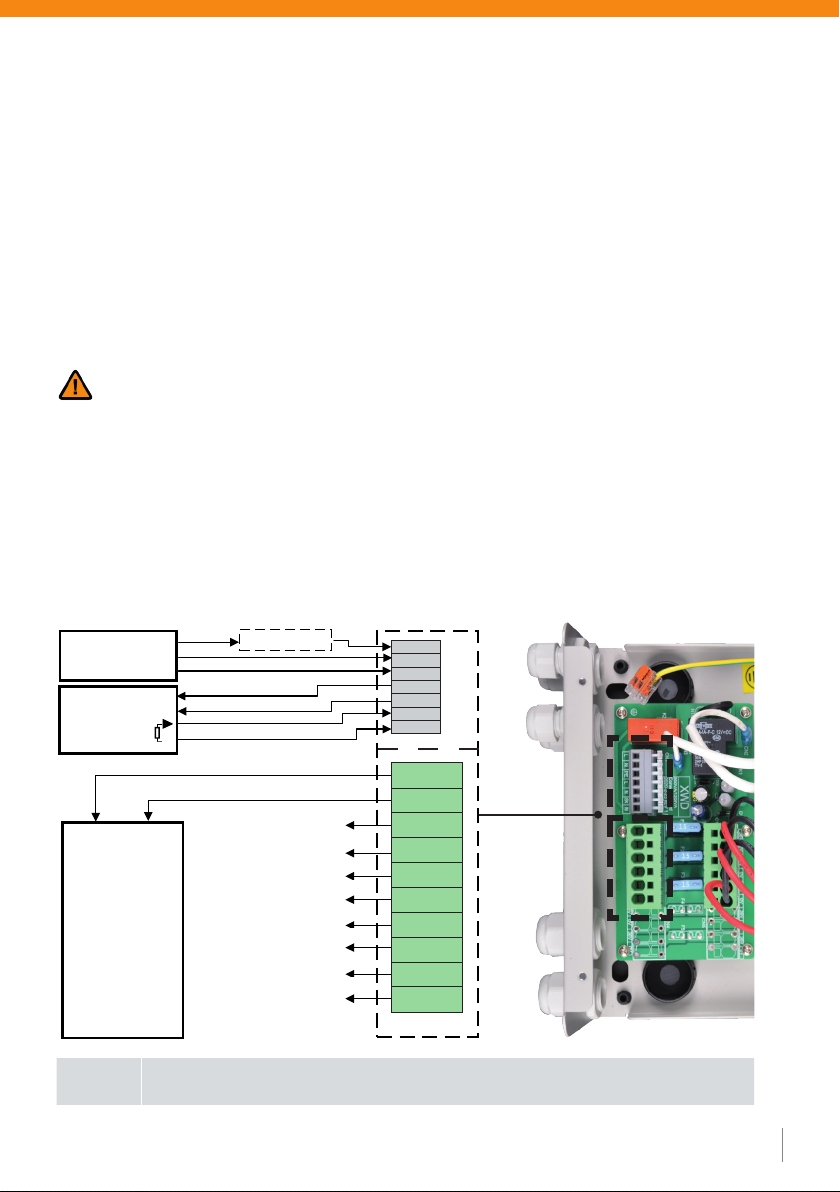
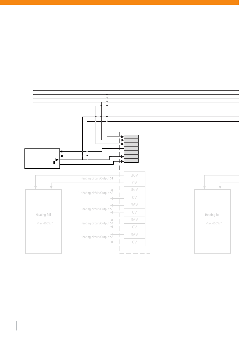
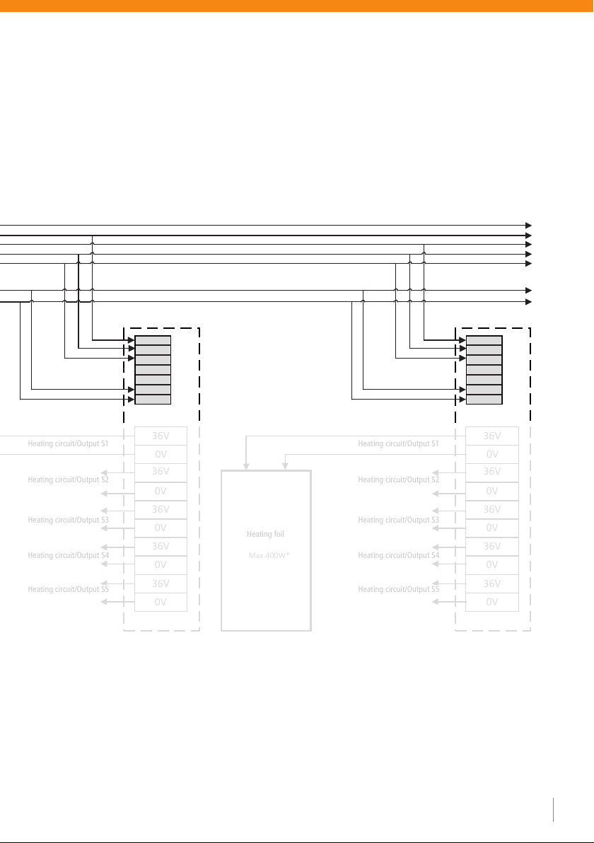
(1) Heating foil (2) Transformer (3) Controller (4) Sensor

08
Umax W/(m2*K) Rmin m2*K/W
Mezzanine floors above heated rooms 1,25 0,75
Mezzanine floors above partially heated rooms 0,75 1,25
Heating surfaces between outside air or ground 0,35 2,86
Basement ceilings, walls or ceilings against unheated rooms 0,35 2,86
Minimum heat transfer coefficient and minimum thermal resistance of components.
plugs for electrical insulation. In addition, two screws must not be fitted with an electrically conductive material
(e.g. metal picture frame, metal trim, metal shelving system). Do not use nails.
3.2.1. Pretreatment of the substrate
The heating foil can be applied to any load-bearing, clean and level surface made of inorganic materials such as
stone, screed, plaster, etc. or organic materials such as wood, cork, plastic (possibly with surface primer / adhesion
promoter), etc. The substrate and top layer materials must be suitable for the use of an electric panel heating
system. If in doubt, contact the manufacturer of these materials.
Irregular surfaces are to be avoided (e.g. visible wood/stone - brickwork). Under certain circumstances, the surface
must be levelled in advance with levelling plaster or levelling compound. Special care must be taken to ensure that
no sharp projections such as stones, screw heads, nails or similar protrude from the substrate.
On walls and ceilings, drywall panels and wood-based panels must be installed to bridge cracks in the joint area.
When installing on the floor, dry screeds and wood-based panels must always be laid in two layers and offset.
For a floating installation without gluing, e.g. between screed and laminate, we recommend approx. 2 mm of
levelling cork layer or glass fibre fleece should be laid under the heating foil.
3.2.2. Thermal insulation
Thermal insulation in the floor and wall area is recommended to reduce the heat emission into the masonry and
the floor. In order to limit the downward heat flow, the following minimum ratio of the heat transfer coefficient of
the floor structure above the insulation layer and the heat transfer coefficient for all layers below the load distribu-
tion layer must be maintained (according to EN 50559:2013-12):
•Mezzanine floor, above heated rooms: U max: 1.25 W/(m2*K)
•Mezzanine floors above partially heated rooms: U max: 0.75 W/(m2*K)
•basement ceilings, walls and ceilings against unheated rooms as well as ceilings and walls that are connected to
the ground border: U max: 0.35 W/(m2*K)
The insulation layers under the floor construction should be selected according to the following table. Minimum
heat transfer coefficients must be observed. Only standardised insulation materials suitable for underfloor heating
may be used. The compressibility of the insulation layer must not exceed 5 mm. If several layers are used, the
compressibility of the individual layers must be added together.

3.2.3 Installation methods
There are three different types of installation:
(A) Embedding the film between inorganic layers with dispersion fillers or dispersion plaster systems such as
Schönox FS, Brillux PM1881 or Maxit K+B.
(B) Bonding of the film between inorganic and organic layers with all types of flexible adhesives as
described under (A).
(C) Floating installation on floor and ceiling as top layer under the top layer.
In cases (A) - (B), the foil is to be worked in the thin-bed method in a moist adhesive bed without air bubbles. To
do this, apply the adhesive bed 1-2 mm thick to the substrate, then carefully press the foil into the still damp bed
with a plastic trowel. The copper contact strips always face the wall. After the heating foil has been glued in, a
complete covering layer (filler, plaster system, tile, etc.) of at least 2 mm must be applied. If several heating foils
are to be laid next to each other, it must be ensured that a minimum distance of 20 mm is maintained between the
individual foils.
It must be ensured that the foil is not laid over expansion joints.
If several heating strips are to be laid floating next to each other according to installation method (C), it must be
ensured that the heating strips are secured against slipping with adhesive tape and that a minimum distance of
20 mm is maintained between the individual foils. The heating tracks and copper contact strips must not touch
or cross each other when laid in multiple tracks. The ends/joints of the foil must always be taped with insulating
adhesive tape (even with uncut strips). For the installation of the controller and sensor, see section Electrical
connection.
3.2.4. Installation under tiles
Before the tiles are bonded, the heating foil must be completely laid with flexible tile adhesive using a thin-bed
method and a 1-2 mm thick top layer. The surface must be dried according to the instructions of the adhesive
manufacturer. When laying several strips, ensure that the surface is level.
09
Notice Further information can be found in the QR code on the back
Sealings in wet areas are applied above the heating foil.
8
Für eine schwimmende Verlegung ohne Verklebung, z.B. zwischen
Estrich und Laminat, empfehlen wir, eine ca. 2 mm ausgleichende Kork-
schicht oder Glasfaservlies unter der Heizfolie zu verlegen.
3.2.2 Wärmedämmung
Eine Wärmedämmung im Boden und Wandbereich ist zu empfehlen,
um die Wärmeabgabe ins Mauerwerk und den Boden zu reduzieren.
Um den Wärmefluss nach unten zu begrenzen, ist folgendes Mindest-
verhältnis der Wärmedurchgangskoeffizienten des Fußbodenaufbaues
oberhalb der Dämmschicht und des Wärmedurchgangskoeffizienten
für alle Schichten unterhalb der Lastverteilschicht einzuhalten (nach EN
50559:2013-12):
• Zwischengeschossdecke, über beheizten Räumen:
U max: 1,25 W/(m2*K)
• Zwischengeschossdecken über teilweise beheizten Räumen:
U max: 0,75 W/(m2*K)
• Kellerdecken, Wände und Decken gegen unbeheizte Räume sowie
Decken und Wände, die an das Erdreich grenzen:
U max: 0,35 W/(m2*K)
Die Dämmschichten unter der Fußbodenkonstruktion sind nach fol-
gender Tabelle zu wählen. Mindest-Wärmedurchgangskoeffizienten
sind einzuhalten. Es dürfen nur genormte, für Fußbodenheizung geeig-
nete Dämmstoffe verwendet werden. Die Zusammendrückbarkeit der
Dämmschicht darf nicht mehr als 5 mm betragen. Bei mehreren Lagen
ist die Zusammendrückbarkeit der einzelnen Lagen zu addieren.
Umax
W/(m2*L)
Rmin
m2*K/W
Zwischengeschossdecken über beheizten
Räumen 1,25 0,75
Zwischengeschossdecken über teilweise
beheizten Räumen 0,75 1,25
Heizflächen zwischen Außenluft oder Erdreich 0,35 2,86
Kellerdecken, Wände oder Decken gegen
unbeheizte Räume 0,35 2,86
Mindest-Wärmedurchgangskoeffizient und Mindest-Wärmeleitwider-
stand der Bauteile.
If the heating film is being installed without adhesive, e.g. between screed
and laminate, we recommend the inclusion of roughly 2 mm of a cork layer
or fibreglass matting underneath the heating film to compensate for this.
3.2.2 Heat insulation
Heat insulation in the floor and walls is recommended, in order to re-
duce the loss of heat to the walls and floor. To limit heat radiation down-
wards, the following minimum ratio of the heat transfer coefficient of
the floor structure above the insulation layer and the heat transfer coef-
ficient of all layers underneath the load distribution layer must be obser-
ved (according to EN 50559:2013-12):
• Intermediate ceilings, above heated rooms:
U max: 1.25 W/(m2*K)
• Intermediate ceilings, above rooms that are heated to some extent:
U max: 0.75 W/(m2*K)
• Cellar ceilings, walls and ceilings next to unheated rooms as well as
ceilings and walls adjacent to earth:
U max: 0.35 W/(m2*K)
The insulation layers below the floor structure must be chosen in ac-
cordance with the following table. Minimum heat transfer coefficients
must be observed. Standardised insulation materials that are suitable
for underfloor heating must be used. The insulation layer must not be
compressible by more than 5 mm. If there are several layers, the com-
pressibility of the individual layers is added together.
Umax
W/(m2*L)
Rmin
m2*K/W
Intermediate ceilings above heated rooms 1.25 0.75
Intermediate ceilings above rooms that are
heated to some extent 0.75 1.25
Heating areas between outside air or earth 0.35 2.86
Cellar ceilings, walls or ceilings next to unhea-
ted rooms 0.35 2.86
Minimum heat transfer coefficient and minimum heat conductivity of
the components.
Wärmedämmung und Verlegung als Direktheizung im Dünnbettkleber Heat insulation and installation as direct heating in thin bed adhesive
Thermal insulation and laying as
direct heating in thin-bed adhesive.
Floor covering
Heating foil
Thin bed adhesive
Screed
Cover
Insulation layer
load-bearing floor

10
4. Electrical connection
The installation of the electrical components may only be carried out by an approved electrician. For the heating
system, an all-pole disconnecting device from the mains with a contact opening width of at least 3 mm per pole in
the fixed installation must be provided. Before commissioning the application, all connections and screws must be
checked.
A residual current switch (RCD with 30 mA) is necessary as indirect protection against accidental contact.
Only a maximum of 400 W may be connected to the individual terminals of the Basic TT power supply units. The
maximum lengths of the individual heating tracks are:
E-NERGY CARBON FLEECE – 36 W/lfm (60 W/m²) max. 11 m
E-NERGY CARBON FLEECE – 66 W/lfm (110 W/m²) max. 6 m
E-NERGY CARBON FLEECE – 132 W/lfm (220 W/m²) max. 3 m
E-NERGY CARBON FLEECE S – 25 W/lfm (145 W/m²) max. 16 m
E-NERGY CARBON FLEECE S – 50 W/lfm (290 W/m2) max. 8 m
E-NERGY CARBON PET – 69 W/lfm (115 W/m²) max. 5,8 m
By means of the floor sensor connection set the temperature sensor is as close as possible to the heating foil sur-
face to be installed. The metal end cap of the connection set must be taped with insulating tape to avoid residual
currents. The temperature sensor is connected to the room thermostat (see operating instructions). Connection and
commissioning must be carried out by a qualified electrician.
Attention: If the measured resistance values deviate by more than 15% from the output value, damage to the
contacts or the heating foil must be expected. In this case you must not put the heating system into operation.
The power supply unit can be installed surface-mounted or flush-mounted. Adequate ventilation must always be
provided. The ambient temperature must not exceed the maximum value of +40 °C. A minimum distance of
50 mm between power supply unit and foil must be maintained. The maximum cable length on the secondary side
of the power supply unit must not exceed
10 m with 2,5 mm2cable
25 m with 6 mm2cable
We recommend the use of our PUR twin cable for surface and flush mounting.
The electrical cables must be laid in accordance with the currently valid DIN VDE 0100.
3.2.5. Ceiling installation
When installing the E-NERGY CARBON heating foil in a suspended ceiling or if it is accessible from a roof space, a
warning sign „Ceiling heating direct acting“ must be attached to the ceiling access opening.
3.2.6 Use in humid/wet rooms
When used in humid/wet rooms, the requirements of DIN VDE 0100 Part 701 must be observed. The transformer
and the other components are basically suitable for use in damp and wet rooms, but may only be installed outside
protection area 2.
Notice A maximum of 400 W may be connected per connection.
The connected total power must not exceed the rated power of the power supply unit.

11
4.1. Overview power supply of E-NERGY CARBON (see Figure 1)
AInput terminals primary side 230 V (L, N, PE)
BOutput terminals secondary side 36 V
CConnection room thermostat 230 V (L, N, SK, N)
Dheating circuit fuses, 15 A each
EConnection protective conductor for housing cover
Figure 1 (Example power supply unit BASIC TT 800 W AP/UP)
C
D
E
B
A
Network connection L
Supply terminal room thermostat L
Network connection N
Supply terminal room thermostat N
Network connection PE
Switch contact SK
Switch contact N

12
4.2. Installation of transformer
The E-NERGY CARBON Power Supply BASIC TT is referred to as a device in the manual.
The device may only be installed in closed rooms. It is designed for surface-mounted and
Suitable for flush mounting and must be protected from moisture, heavy dust, aggressive liquids and vapors.
Always ensure sufficient heat dissipation (distance to thermal insulation) and ventilation.
An ambient temperature not exceeding 40 °C must not be exceeded.
Any interventions or changes to the power supply lead to exclusion of guarantee or warranty and can destroy the
system! The warranty is void if the fault is due to an accident, use of force, incorrect connection, penetration of
liquids, poor maintenance or misuse. The warranty is also void if the damage is caused by thunderstorms or other
voltage variations.
Select the installation site taking into account the safety instructions and the following
points of view carefully:
• The maximum cable length between the heating track and the device is 10 m (2.5 mm2) or 25 m (6 mm²).
Place the device in such a way that all heating tracks are accessible with the available cable length.
• Fix the product with the 4 fixing holes on a solid, secure surface.
The surface must be such that the weight of the device is safely supported.
• Screw heads / washers must have a minimum diameter of 15 mm so that the mounting holes are
sufficiently covered.
• Do not mount the device upside down. Always mount the unit vertically so that the ventilation
openings are facing up and down.
• The circuit must not be overloaded by the rated current in heating operation.
• Never cover the transformer and always ensure sufficient ventilation.
A distance of at least 200 mm below and above the transformer is recommended.
• The transformer must be accessible and open for maintenance purposes.

13
Before performing electrical work, the power supply must be disconnected and secured against
being switched on again. The electrical installation may only be carried out by competent persons in
accordance with the applicable legal requirements. The installation must comply with national and/or local
electrical regulations. An earth-leakage circuit breaker (nominal residual current ≤ 30 mA) is required for
each circuit.
4.3 Connection of mains voltage and room thermostat
For connection to the supply voltage, the following specifications must be observed:
Supply voltage 230 VAC, 50/60 Hz
• The electric circuit for the connection must be sufficiently dimensioned and fused.
When operating the heating system, this circuit must not be overloaded.
• Circuit breaker: 16 A (check total load of the electric circuit. A separate supply line with a 16 A circuit
breaker with C-characteristic is recommended)
• All assembly and installation work must always be carried out in a de-energized state.
The device is not ready for operation when delivered and must first be connected by a qualified electrician.
Variant 1: Connection room thermostat 230 V
The electronics of the BASIC TT power supply unit are designed for the connection of a room thermostat with
230 V AC. The room thermostat is connected to the room thermostat L supply terminal and room thermostat N
supply terminal (room thermostat 230 V AC supply) as well as to the switching contact SK and switching contact N
(switching contact for switching signal) as shown in the diagram.
Notice A maximum of 400 W may be connected per connection.
The connected total power must not exceed the rated power of the power supply unit.
L
N
PE
L
N
N
SK
36V
36V
36V
36V
36V
0V
0V
0V
0V
0V
L
N
PE
Heizkreis/OutputS1
Heizfolie/Heatfilm
Anschlussschema / Connection scheme
Basic TT 36-400W/800W/1200W AP/UP
DCFilter(optional)
Netzanschluss/
MainsSupply
230V/50Hz
Heizkreis/OutputS2
Heizkreis/OutputS3
Heizkreis/OutputS4
Heizkreis/OutputS5
Thermostat
L
N
230V/50Hz
Last/
Load
Max.400W*
N
*Max. 400 W pro Heizkreis. Die angeschlossene Gesamtleistung der Heizkreise darf die Nennlast des Trafos nicht
überschreiten.
*Max. 400 W per output. The connected total power of the outputs must not exceed the nominal load of the
transformer
L
L
N
N
N
36V
36V
36V
36V
36V
0V
0V
0V
0V
0V
PE
SK
Network connection/ L
Main supply N
230V/50Hz PE
Heating foil
Heating circuit/Output S1
Heating circuit/Output S2
Heating circuit/Output S3
Heating circuit/Output S4
Heating circuit/Output S5

14
Variant 2: Connection of a room thermostat to several Basic TT power supplies
If several power supplies are controlled by one room thermostat, the room thermostat is connected to a power
supply as described in Variant 1. In addition, the switching signal is connected in parallel to the switching contact
SK and switching contact N of the other power supply units. Attention: The supply terminal room thermostat L and
supply terminal room thermostat N remain unassigned with the other power supply units. In the case of power
supply units with production date (KW18 / year 2020) or later, the individual power supply units can also be sup-
plied individually via the conductors L1, L2, L3.
L
N
PE
L
N
N
SK
36V
36V
36V
36V
36V
0V
0V
0V
0V
0V
L
N
PE
Heizkreis/OutputS1
Heizfolie/Heatfilm
Anschlussschema / Connection scheme
Basic TT 36-400W/800W/1200W AP/UP
DCFilter(optional)
Netzanschluss/
MainsSupply
230V/50Hz
Heizkreis/OutputS2
Heizkreis/OutputS3
Heizkreis/OutputS4
Heizkreis/OutputS5
Thermostat
L
N
230V/50Hz
Last/
Load
Max.400W*
N
*Max. 400 W pro Heizkreis. Die angeschlossene Gesamtleistung der Heizkreise darf die Nennlast des Trafos nicht
überschreiten.
*Max. 400 W per output. The connected total power of the outputs must not exceed the nominal load of the
transformer
L
N
PE
L
N
N
SK
36V
36V
36V
36V
36V
0V
0V
0V
0V
0V
L
N
PE
Heizkreis/OutputS1
Heizfolie/Heatfilm
Anschlussschema / Connection scheme
Basic TT 36-400W/800W/1200W AP/UP
DCFilter(optional)
Netzanschluss/
MainsSupply
230V/50Hz
Heizkreis/OutputS2
Heizkreis/OutputS3
Heizkreis/OutputS4
Heizkreis/OutputS5
Thermostat
L
N
230V/50Hz
Last/
Load
Max.400W*
N
*Max. 400 W pro Heizkreis. Die angeschlossene Gesamtleistung der Heizkreise darf die Nennlast des Trafos nicht
überschreiten.
*Max. 400 W per output. The connected total power of the outputs must not exceed the nominal load of the
transformer
L
Network connection
Switch contact SK
Switch contact N
L3
L2
L1
L
N
N
N
N
PE
PE
SK
Heating foil
Heating foil
Heating circuit/Output S1
Heating circuit/Output S2
Heating circuit/Output S3
Heating circuit/Output S4
Heating circuit/Output S5

15
L
N
PE
L
N
N
SK
36V
36V
36V
36V
36V
0V
0V
0V
0V
0V
L
N
PE
Heizkreis/OutputS1
Heizfolie/Heatfilm
Anschlussschema / Connection scheme
Basic TT 36-400W/800W/1200W AP/UP
DCFilter(optional)
Netzanschluss/
MainsSupply
230V/50Hz
Heizkreis/OutputS2
Heizkreis/OutputS3
Heizkreis/OutputS4
Heizkreis/OutputS5
Thermostat
L
N
230V/50Hz
Last/
Load
Max.400W*
N
*Max. 400 W pro Heizkreis. Die angeschlossene Gesamtleistung der Heizkreise darf die Nennlast des Trafos nicht
überschreiten.
*Max. 400 W per output. The connected total power of the outputs must not exceed the nominal load of the
transformer
L
N
PE
L
N
N
SK
36V
36V
36V
36V
36V
0V
0V
0V
0V
0V
L
N
PE
Heizkreis/OutputS1
Heizfolie/Heatfilm
Anschlussschema / Connection scheme
Basic TT 36-400W/800W/1200W AP/UP
DCFilter(optional)
Netzanschluss/
MainsSupply
230V/50Hz
Heizkreis/OutputS2
Heizkreis/OutputS3
Heizkreis/OutputS4
Heizkreis/OutputS5
Thermostat
L
N
230V/50Hz
Last/
Load
Max.400W*
N
*Max. 400 W pro Heizkreis. Die angeschlossene Gesamtleistung der Heizkreise darf die Nennlast des Trafos nicht
überschreiten.
*Max. 400 W per output. The connected total power of the outputs must not exceed the nominal load of the
transformer
L L
L L
N N
N N
N N
PE PE
SK SK
Heating foil
Heating circuit/Output S1
Heating circuit/Output S2
Heating circuit/Output S3
Heating circuit/Output S4
Heating circuit/Output S5

16
4.4 Heating circuit connection
Please note the following: After the heating tracks have been laid, the connecting cables can be connected to the
secondary side of the device. For this purpose, connect the output terminals 36 V (Figure 1, Letter B) to the connec-
tion lines of the heating tracks.
Notice
Per connection (output terminal pair 36 V) max. 400 W may be connected.
The connected total power must not exceed the rated power of the power supply unit.
Variant 3: Connection of a potential-free switching contact
When using a potential-free switching contact, the supply terminal room thermostat L (230 V) is connected to the
switching contact SK via the potential-free contact. In addition, the supply terminal room thermostat N must be
connected to the switching contact N.
L
N
PE
L
N
N
SK
36V
36V
36V
36V
36V
0V
0V
0V
0V
0V
L
N
PE
Heizkreis/OutputS1
Heizfolie/Heatfilm
Anschlussschema / Connection scheme
Basic TT 36-400W/800W/1200W AP/UP
DCFilter(optional)
Netzanschluss/
MainsSupply
230V/50Hz
Heizkreis/OutputS2
Heizkreis/OutputS3
Heizkreis/OutputS4
Heizkreis/OutputS5
Thermostat
L
N
230V/50Hz
Last/
Load
Max.400W*
N
*Max. 400 W pro Heizkreis. Die angeschlossene Gesamtleistung der Heizkreise darf die Nennlast des Trafos nicht
überschreiten.
*Max. 400 W per output. The connected total power of the outputs must not exceed the nominal load of the
transformer
L
L
N
N
N
PE
SK
Relay with
potential-free
contact
Heating foil
Heating circuit/Output S1
Heating circuit/Output S2
Heating circuit/Output S3
Heating circuit/Output S4
Heating circuit/Output S5
Network connection/ L
Main supply N
230V/50Hz PE

17
4.5 Electrical commissioning
The electrical installation work on the device is now complete. Carefully check again that the installation work has
been carried out. For commissioning, switch the supply circuit back on.
After the circuit has been activated and if the installation is correct, the room thermostat will be activated.
When the room thermostat gives the signal for heating, the unit switches on. When the heating cycle is completed,
the unit switches off again.
Test function: To start a test run of the heating system, increase the temperature on the room thermostat until the
heating cycle is started. By reducing the temperature, heating operation is ended again. After successful start-up,
set the room thermostat correctly. For details on setting the temperature, refer to the relevant instructions for the
room thermostat.
5. Commissioning
After a minimum drying time of the adhesive (see manufacturer‘s recommendation) and after electrical
commissioning, the E-NERGY CARBON heating system can be heated up for the first time. Now attach the war-
ning label supplied in the immediate vicinity of the heating foil so that it is clearly visible and place the operating
instructions in the distribution box or a suitable location.
Possible cause Remedy
Heating mode not activated Check the settings on the room thermostat
Power supply interrupted Check all cable connections and terminals.
Check the circuit breaker
Triggering the device fuse Check the device fuse(s) and replace them if necessary with an
identical 15 A flat plug fuse
Triggering of the safety temperature
switch by heat accumulation
Check the temperature of the transformer and make sure
adequate aeration
6. Fault diagnosis
If the device does not function or malfunctions, the following possible causes should help to solve the problem.
If the listed causes do not eliminate the malfunction, contact your contracting party. Observe the safety instruc-
tions. Before checking electrical components or when When performing electrical work, the power supply must be
disconnected and secured against being switched on again.
The electrical inspection and installation may only be carried out by competent persons (qualified electricians) in
accordance with the applicable legal requirements. Never open the device. There is danger to life and connected
components can be destroyed.

18
E-NERGY CARBON power supply unit BASIC TT 400 |800 |1200 W
Nominal power 400W |800 W |1200W
Nominal voltage primary 230 V AC 50/60 Hz
Nominal voltage secondary 36 V AC (SELV, Safety Extra Low Voltage)
Power supply 230 V (primary) Spring clamp terminals 1,5 mm² – 2,5 mm²
Connection room thermostat 230 V Spring clamp terminals 1,5 mm² – 2,5 mm²
Connection heating foils 36 V (secondary) Spring clamp terminals 2,5 mm² bis 6,0 mm²
Number of connections heating foil* 1 |3 |5
Fuse protection per connection heating foil 15 A
Ambient temperature Max. 40°C
Internal safety temperature switch 130°C automatic resetting
Insulation material class B
Housing protection class IP20
Dimensions (L x W x H) 400 W: 250x173x75 mm | 800 W: 300 x 220 x 85 mm
1200 W: 300 x 220 x 85 mm
Weight 400 W: ca. 6,0 kg | 800 W: ca. 13,0 kg | 1200 W: ca. 14,0 kg
Type Toroidal Core
Protection class IEC/EN I
EU Conformity CE mark, according to EN 61558-2-6, European Low Voltage Directive
2014/35/EU, EMC Directive 2014/30/EU and RoHS 2011/65/EU
Waste management
WEEE-Reg.-Nr. : DE 97703783
E-NERGY CARBON room thermostat
see installation and operating instructions Room thermostat
7. Technical data
* A maximum of 400 W may be connected per connection. The connected total power must not exceed the rated
power of the power supply unit.

19
a) Disposal note: The product must not be disposed of in general household waste! Recycling via electronic-
disposal of the municipal collection points.
b) Permissible installation as ceiling heating (direct acting)
c) Permitted installation as underfloor heating (direct acting)
d) Read the operating instructions, follow the instructions
12
4 TECHNISCHE DATEN
Netzspannung: 230 V AC
Stromeinspeisung: 1,74 A je 400 W Belastung
Leistung
(hicoTHERM®36-Heizfolie): 60 W/m2(hicoTHERM® 36-60)
110 W/m2(hicoTHERM® 36-110)
220 W/m2(hicoTHERM® 36-220)
Leistung pro Laufmeter: 35 W / lfm (hicoTHERM® 36-60)
65 W / lfm (hicoTHERM® 36-110)
130 W / lfm (hicoTHERM® 36-220)
Sekundärspannung: 36 V
Absicherung: 12 A AP
15 A UP
Schutzmaßnahme: FI-Schutzschaltung 30 mA
Nenngrenztemperatur: + 70 °C
Mindestverarbeitungstemperatur: + 5 °C
Minimaler Biegeradius: R10 mm
Material: PET-Folie mit Carbonfasern
und Füllstoffen
Primärleitung Netzteil: 1,5 mm2
Sekundärleitung Netzteil: 2,5 mm2, max. 10 m Länge
6,0 mm2, max. 25 m Länge
Heizfolienabmessung, Breite: 59 cm
54 cm (netto Heizbreite)
Maximallänge: hicoTHERM® 36-60 max. 11 m
hicoTHERM® 36-110 max. 6 m
hicoTHERM® 36-220 max. 3 m
Max. Wärmedurchlasswiderstand: Rλfür Bodenbelag: 0,15 m2K/W
Symbolerklärung:
a) Entsorgungshinweis: Das Produkt darf nicht im allgemeinen
Hausmüll entsorgt werden! Recycling über Elektronikentsorgung
der kommunalen Sammelstellen.
b) Zulässiger Einbau als Deckenheizung (direkt wirkend)
c) Zulässiger Einbau als Fußbodenheizung (direkt wirkend)
d) Bedienungsanleitung lesen, Anleitungen befolgen
e) Schutzklasse II
4 TECHNICAL DATA
Mains voltage: 230 V AC
Power input: 1.74 A per 400 W load
Output
(hicoTHERM®36 heating film): 60 W/m2(hicoTHERM® 36-60)
110 W/m2(hicoTHERM® 36-110)
220 W/m2(hicoTHERM® 36-220)
Output per metre: 35 W / m (hicoTHERM® 36-60)
65 W / m (hicoTHERM® 36-110)
130 W / m (hicoTHERM® 36-220)
Secondary voltage: 36 V
Fuse protection: 12 A surface-mounted
15 A flush-mounted
Protection measure: FI circuit breaker 30 mA
Nominal temperature limit: + 70 °C
Minimum processing temperature: + 5 °C
Minimum bending radius: R10 mm
Material: PET film with carbon fibres
and fillers
Primary conductor/power supply unit: 1.5 mm2
Secondary conductor/power supply unit: 2.5 mm2, max. 10 m length
6.0 mm2, max. 25 m length
Heating film dimensions, width: 59 cm
54 cm (net heating width)
Minimum lengths: hicoTHERM® 36-60 max. 11 m
hicoTHERM® 36-110 max. 6 m
hicoTHERM® 36-220 max. 3 m
Max. heat transfer resistance: Rλfor floor covering: 0.15 m2K/W
Explanation of symbols:
a) Waste disposal instructions: the product may not be disposed of in
general household waste! It must be recycled via the electronics
waste disposal system organised by the local authorities.
b) Approved for installation as a ceiling heating system (direct impact)
c) Approved for installation as an underfloor heating system
(direct impact)
d) Read and follow the instructions
e) Protection class II
Explanation of symbols:
E-NERGY CARBON heating foils
Voltage 36 V
Heating foil dimension, width FLEECE & PET: 59 cm, 54 cm (net heating width)
FLEECE S: 17 cm, 12 cm (net heating width)
Maximum length
E-NERGY CARBON FLEECE – 36 W/lfm (60 W/m²) max. 11 m
E-NERGY CARBON FLEECE – 66 W/lfm (110 W/m²) max. 6 m
E-NERGY CARBON FLEECE – 132 W/lfm (220 W/m²) max. 3 m
E-NERGY CARBON FLEECE S – 25 W/lfm (145 W/m²) max. 16 m
E-NERGY CARBON FLEECE S – 50 W/lfm (290 W/m2) max. 8 m
E-NERGY CARBON PET – 69 W/lfm (115 W/m²) max. 5,8 m
Nominal limit temperature + 70 °C
Minimum processing temperature + 5 °C
Minimum bending radius R10 mm
Material PET film with carbon fibres and fillers
Connection cable 2,5 mm²
Secondary line between power supply
unit and heating foil
2,5 mm2, max. 10 m length
6,0 mm², max. 25 m length
Max. Thermal resistance R
λ
for floor covering: 0,15 m² K/W

20
E-NERGY CARBON FLEECE – 36 W/lfm (60 W/m²) max. 11 m
E-NERGY CARBON FLEECE – 66 W/lfm (110 W/m²) max. 6 m
E-NERGY CARBON FLEECE – 132 W/lfm (220 W/m²) max. 3 m
E-NERGY CARBON FLEECE S – 25 W/lfm (145 W/m²) max. 16 m
E-NERGY CARBON FLEECE S – 50 W/lfm (290 W/m²) max. 8 m
E-NERGY CARBON PET – 69 W/lfm (115 W/m²) max. 5,8 m
Per connection (output terminal pair 36 V) max. 400 W may be connected. The connected total power must not
exceed the rated power of the power supply unit.
The power supply unit can be installed surface-mounted or flush-mounted. Adequate ventilation must always be
provided. The ambient temperature must not exceed the maximum value of +40 °C.
The secondary cable between power supply unit and heating foil must not exceed 10 m at a cable cross section of
2.5 mm² and a maximum of 25 m with a wire cross-section of 6.0 mm².
Length
FLEECE
36 W/lfm
(60 W/m²)
FLEECE
66 W/lfm
(110 W/m²)
FLEECE
132 W/lfm
(220 W/m²)
FLEECE S
25 W/lfm
(145 W/m²)
FLEECE S
50 W/lfm
(290 W/m²)
PET
69 W/lfm
(115 W/m²)
0,1 m 365,84 Ω 199,06 Ω 99,53 Ω 516,00 Ω 262,80 Ω 188,30 Ω
0,2 m 182,92 Ω 99,53 Ω 49,77 Ω 258,00 Ω 131,40 Ω 94,15 Ω
0,3 m 121,95 Ω 66,35 Ω 33,18 Ω 172,00 Ω 87,60 Ω 62,77 Ω
0,4 m 91,46 Ω 49,77 Ω 24,88 Ω 129,00 Ω 65,70 Ω 47,08 Ω
0,5 m 73,17 Ω 39,81 Ω 19,91 Ω 103,20 Ω 52,56 Ω 37,66 Ω
0,6 m 60,97 Ω 33,18 Ω 16,59 Ω 86,00 Ω 43,80 Ω 31,38 Ω
0,7 m 52,26 Ω 28,44 Ω 14,22 Ω 73,71 Ω 37,54 Ω 26,90 Ω
0,8 m 45,73 Ω 24,88 Ω 12,44 Ω 64,50 Ω 32,85 Ω 23,54 Ω
0,9 m 40,65 Ω 22,12 Ω 11,06 Ω 57,33 Ω 29,20 Ω 20,92 Ω
1,0 m 36,58 Ω 19,91 Ω 9,95 Ω 51,60 Ω 26,28 Ω 18,83 Ω
1,1 m 33,26 Ω 18,10 Ω 9,05 Ω 46,91 Ω 23,89 Ω 17,12 Ω
1,2 m 30,49 Ω 16,59 Ω 8,29 Ω 43,00 Ω 21,90 Ω 15,69 Ω
1,3 m 28,14 Ω 15,31 Ω 7,66 Ω 39,69 Ω 20,22 Ω 14,48 Ω
1,4 m 26,13 Ω 14,22 Ω 7,11 Ω 36,86 Ω 18,77 Ω 13,45 Ω
1,5 m 24,39 Ω 13,27 Ω 6,64 Ω 34,40 Ω 17,52 Ω 12,55 Ω
1,6 m 22,87 Ω 12,44 Ω 6,22 Ω 32,25 Ω 16,43 Ω 11,77 Ω
1,7 m 21,52 Ω 11,71 Ω 5,85 Ω 30,35 Ω 15,46 Ω 11,08 Ω
1,8 m 20,32 Ω 11,06 Ω 5,53 Ω 28,67 Ω 14,60 Ω 10,46 Ω
1,9 m 19,25 Ω 10,48 Ω 5,24 Ω 27,16 Ω 13,83 Ω 9,91 Ω
2,0 m 18,29 Ω 9,95 Ω 4,98 Ω 25,80 Ω 13,14 Ω 9,42 Ω
2,1 m 17,42 Ω 9,48 Ω 4,74 Ω 24,57 Ω 12,51 Ω 8,97 Ω
2,2 m 16,63 Ω 9,05 Ω 4,52 Ω 23,45 Ω 11,95 Ω 8,56 Ω
2,3 m 15,91 Ω 8,65 Ω 4,33 Ω 22,43 Ω 11,43 Ω 8,19 Ω
*If the measured resistance values deviate more than 15 % from the initial value, damage to the contacts or the
heating foil. In this case you must not start up the heating system.
8. Resistance values as a function of length*
This manual suits for next models
3
Table of contents
Other mfh systems Power Supply manuals