mfh systems AP 100 User manual
mfh systems
modern floor heating
mfh systems
modern floor heating
Power supply unit AP 100
E-NERGY CARBON system
Installation instructions

Contents
1. General information and safety instructions
1.1 Scope of delivery
1.2 Overview
1.3 Safety Instructions
2. Installation instructions
2.1 Introduction Assembly
2.2 Assembly
2.3 Mains voltage connection
2.4 Connection of the heating circuits
2.5 Temperature sensor
2.6 Commissioning
2.7 Adjusting the temperature sensor
3. Technical data
02

1. General information and safety instructions
The E-NERGY CARBON AP 100 power supply unit is referred to as a device in the instructions. The unit is intended
for independent temperature control of wall sections. The unit uses an external temperature sensor to regulate the
surface temperature to 16 °C to prevent the formation of mould.
The appliance can be used by children aged 8 years and older and by persons with reduced physical,
sensory or mental abilities or lack of experience and knowledge if they have been supervised or
instructed in the safe use of the appliance and understand the resulting dangers. Children must not play
with the device. Cleaning and user maintenance must not be performed by children without supervi-
sion. In humid/wet rooms, DIN VDE 0100 Part 701 must be observed.
Any intervention or modification of the device leads to the exclusion of warranty or guarantee and can destroy
the system! The warranty is void if the fault is due to an accident, use of force, incorrect connection, infiltration
of fluids, poor maintenance or misuse. The warranty is also void if damage has occurred due to thunderstorms or
other voltage variations.
1.1. Scope of delivery E-NERGY CARBON power supply AP 100
The device is a power supply and control unit specially designed for use with E-NERGY CARBON heating systems.
The scope of delivery includes the following individual parts:
1 x Power supply E-NERGY CARBON with mains plug Includes temperature sensor
1 x Wall mount
1 x Installation instructions
Please leave the device in its original packaging until installation.
03
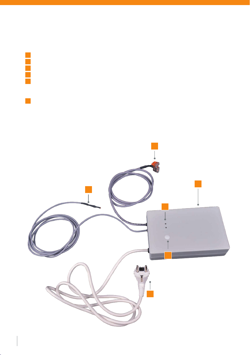
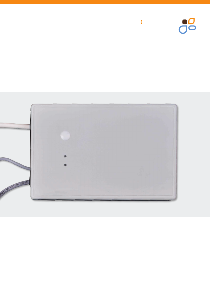
1.2. Overview E-NERGY CARBON power supply AP 100 (see Figure 1)
APower supply cable 1 m
BTemperature sensor 2.5 m
CSecondary connection 1 m (heating track connection)
DHousing Power supply unit
ELED operation display
Green = Standby
Yellow = heating operation
FPotentiometer cover
Figure 1
04
B
A
E
C
D
F

1.3. Safety Instructions
• Please read this manual carefully and completely before starting the installation.
• Transport: To protect all parts from damage, they should be transported to the installation site in the
remain in their original packaging. Internal parts can be damaged by shock and fall.
• Damaged devices or parts must not be put into operation.
• The safety stickers and type plates must not be removed.
• The individual components may only be installed in closed rooms.
• All installation and installation work must always be carried out in a de-energized state
(unplugged power plug).
• The socket or circuit for connecting the heating control unit must be sufficiently be measured and secured.
When operating the heating system, this circuit must not be overloaded.
• The unit is supplied with a mains plug. All electrical parts,
which carry a mains voltage of 230 V are protected against direct contact.
• Never carry or pull the unit by the power cable. Never pull the plug by the power cord or pull out of the socket
with wet hands.
• Protect the device from moisture, strong dust, aggressive liquids and vapours.
• Clean the device with a soft, slightly damp or antistatic cloth. Do not use cleaning agents or chemical substances.
05
2. Installation instructions for the E-NERGY CARBON Power Supply AP 100
2.1. Introduction Installation
When planning your system, remember that you operate the device with the pre-assembled mains connection
cable (Fig.: 1, A) at a normal shockproof socket. The heating control unit is prepared for this operating mode when
delivered. It offers the advantage that only a small installation effort is required.
2.2. Installation
Select the installation location carefully, taking the following aspects into account:
• The power cable (Fig.: 1, A) has a length of 1 meter. Mount the device accordingly in near a shockproof socket.
• The cable length between the heating track and the device is 1 m (1 mm2 ). Place the unit so that all
heating tracks can be reached with the available cable lengths.The secondary lines (Fig.: 1, C) can be used if
can be extended to a total length of max. 10 m (2.5 mm²) or max. 25 m (6 mm²).
• The circuit must not be overloaded by the rated current occurring during operation of the heater.
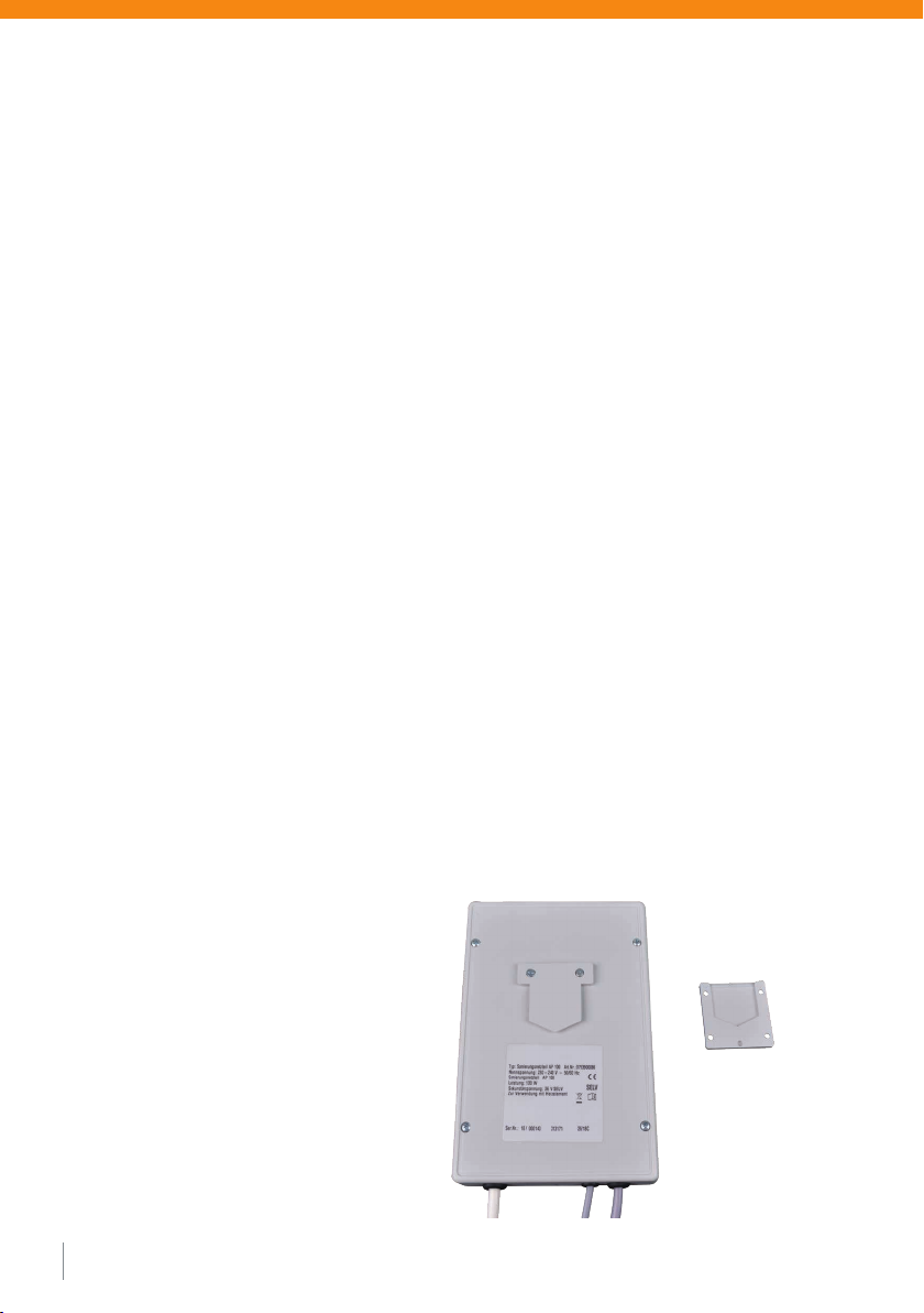
• The device can be surface mounted on a wall using a wall bracket.
• To do so, mount the wall bracket (Fig.: 2) with the recess facing the wall, then the device can be plugged in.
• The device can be flush-mounted, but please note that the lines (primary and secondary), and the temperature
sensor must be laid in an installation pipe. The connection point of the the secondary line with the heating
track must be installed in a junction box or in a cable duct.
06
Figure 2: Wall mounting bracket

2.3 Mains voltage connection
The following specifications must be observed for connection to the power supply system.
Supply voltage 230-240 VAC, 50/60 Hz
2.4 Connection heating circuits
Please note the following:
After the heating tracks have been laid, the connecting cables can be connected to the secondary line of the unit.
To do this, connect the connection lines of the heating tracks to the secondary line (see Fig.: 1 / C) of the unit in a
junction box / flush-mounted box or in the cable duct.
A maximum of 100 W heating power may be connected.
The secondary line between the power supply unit and the heating track must not exceed a total length of max. 10
m (2.5 mm²) or max. 25 m (6 mm²).
2.5 Temperature sensor
The temperature sensor should be installed at the coldest point in the masonry to obtain the best possible
temperature control. To do this, guide the sensor with the floor sensor connection set to the desired location and
lay it behind the heating foil in the masonry.
The temperature threshold is 16 °C, the unit automatically regulates the temperature at the desired point to this value.
2.6 Commissioning in the as-delivered condition
The electrical installation work on the device is now complete. Carefully check again that the installation work has
been carried out. For commissioning, the mains plug is plugged into the intended grounded contact socket.
The green LED then lights up to indicate the standby mode during heating operation, the yellow LED
also lights up (see Fig.: 1 / E).
The temperature sensor (see Fig.: 1 / B) now automatically regulates the temperature at the installed location.
If the temperature falls below 16 °C the unit switches on and if it exceeds 16 °C the unit switches off again.
2.7 Adjustment of the temperature sensor
The temperature threshold of the sensor can be adjusted via a potentiometer. The potentiometer is located under the
white cover on the front (Fig.: 1 / F).
After removing the cover, you can adjust the temperature with a screwdriver.
Left stop = 16 °C
Right stop = 30 °C
07

mfh systems GmbH
Hager Feld 8
49191 Belm-Vehrte
Germany
Fon +49 (0) 54 06 | 699 95-10
Fax +49 (0) 54 06 | 699 95-90
mail@mfh-systems.com
www.mfh-systems.com
mfh systems
modern floor heating
mfh systems
modern floor heating
3. Technical data
100 W
Input voltage 230 V +- 10 % AC, 50/60Hz
Output power 100 VA
Rated current 2,78 A
Efficiency 86.3 %
Protection class IP 54
Network connection Protective contact plug
Output voltage per heating circuit 36 V AC
Mounting Wall mounting, flush mounting
Maximum ambient temperature 30 °C
Operating displays Green + Yellow LED
Dimensions (L x W x H) 186 x 123 x 41 mm
Weight 1.6 kg
Pb
LEAD FREE
Im Einklang mit RoHS
Table of contents
Other mfh systems Power Supply manuals

Popular Power Supply manuals by other brands

Thermaltake
Thermaltake W0117 Specifications

INIM Electronics
INIM Electronics SmartLevel SPS24060S installation manual

Spellman
Spellman MXR Series Installation and user guide

IFM
IFM AS-Interface AC1254 installation manual

Lenovo
Lenovo ThinkSystem SR650 quick start guide

hager
hager 2904 installation instructions


