MFJ MFJ-8504 User manual


MFJ-8504 Dual Antenna Quad Receiver Multicoupler
Features:
ɀ Flat gain, less than 3dB variation 300 kHz to 850 MHz
ɀ Low-noise high dynamic range ush- ull am lifier
ɀ 30-35 dBm out ut TOI ty ical
ɀ U to two in ut orts and four out ut orts
ɀ In ut orts can be s lit by frequency range using o tional dual internal filters.
ɀ O tional band reject, band ass, low ass, or high ass filters available
ɀ BNC in uts, SMA out uts standard
ɀ 9-15 volt dc at 150 mA nominal su ly voltage
ɀ Internal unused ort termination standard
ɀ Rugged construction
ɀ Fully shielded enclosure
ɀ Reverse olarity ower su ly rotected with internal fuse
The MFJ-8504 is an am lified, single or dual in ut, one to four out ut, broadband receiver multicou ler.
This broadband cou ler has excellent erformance over a very wide frequency range, from below 300
kHz to above 500 MHz.
This is a low-noise gain-neutral device. It em loys modern low noise ush- ull high interce t MMIC
devices, carefully selected for o timal erformance. Out ut IP3 is ty ically 30-35 dBm.
Overload in any system like this is a function of the total ower a lied to the in ut from multi le signals,
or the composite input power. Undesired signals still use u art of the am lifier headroom. If too much
headroom is taken u by undesired signals, multi le signals will mix and generate new hantom signals.
This unit has rovisions to add o tional internal lug-in filters to reduce or remove unwanted or
roblematic frequency ranges.
While this unit is generally as safe as any SDR receiver, it is best to kee receive antenna(s) well away
from any active transmitting antennas.

Quick Start
1. Connect your receiver(s) to the out ut orts, antenna(s) to the antenna orts.
Note: Unless optional band splitting filters are installed and internal input jumpers are
reconfigured, antenna port 1 is the only active input port. Receiver port 1 is the primary active
output port. Receivers connected to ports 2-4 will function, but it is best to remove the appropriate
blac jumper shunt terminating ports 2-4 when using a port.
2. Connect a 12Vdc nominal voltage, 150 mA or higher ower source to the right rear standard
ower connector. The lug must be center in ositive. Use a good well-filtered su ly.
Connectors
The MFJ-8504 has two standard BNC in ut connectors. It is best to kee the receive antenna(s) well
away from any transmitting antennas. This unit is generally as safe as any SDR receiver.
The maximum safe net ower a lied to these terminals is 20 dBm or 3.2 volts eak. With filters safe
level fully outside filter ass band can be u to 15 volts RMS (36 dBm).
The MFJ-8504S has four standard SMA out ut connectors. The MFJ-8504B has four standard BNC
out ut connectors. For best erformance unused out uts should be terminated with 50-75 ohm
terminations. Terminations are built in to the units.
Provisions have been made for the following. (These features require urchase of additional high ass
and low ass filters).
Frequency split to dual inputs this feature allows se arate low band / high band antennas. Any filter
can be used se arately on any antenna in ut ort. Filters can also be connected in arallel or in series
from a single ort. We currently have an 8- ole broadcast band reject, 1.7 MHz 5- ole High Pass, and 30
MHz Low Pass and High Pass 5- ole filters. The filters can be set u in multi le ways for s ecific needs.
The user must calculate the values and make his own non-standard filters.
ɀ Band Pass 10- ole filters allow selection of a favorite ass band of limited bandwidth such as
broadcast or a articular Ham band.
ɀ Band-reject 8- ole filters reject an undesired frequency range such as the AM broadcast band.
ɀ Low Pass 5- ole filter asses all frequencies above a cut off limit.
ɀ High Pass 5- ole filter asses all frequencies below cut off limit.
ɀ Low Pass and High Pass can be used in tandem to form a wide Band Pass or wide band reject of
almost any width. For exam le a 1.7MHz High Pass can be used in series with a 30MHz Low
Pass to form a 1.7-30MHz Band Pass. A 1.7MHz Low Pass is in arallel with a 30 MHz High
Pass forms a 1.7-30 MHz band reject.
This unit allows any configuration of u to two filters.
Typical Configuration
Connect a 9-15 Vdc, 150 mA or higher ower source to the right rear 2.1 mm 12V connector. The lug
must be center in ositive, negative to the outer shell. Be sure the ower source is relatively clean of
hum and high frequency noises. While the ower jack is noise filtered and decou led, some ower
su lies can introduce noise or re eating birdies. This is es ecially true if your antenna system and cable
wiring has oor common mode current isolation.
In rare cases isolating the ower su ly from other devices, such as using a dedicated higher-quality
linear (non-switch mode) wall su ly, might be necessary.
Receiver 1 is the riority receiver out ut. This should be the first receiver ort connected. This unit is
shi ed with additional Receiver orts terminated in 50 ohms internally. If additional Receiver orts are
used, they can be added in any order.

When activating any Receiver ort other than ort 1, it is best to disable the internal termination for that
ort. Removing the cover, you will find a conventional black jum er or “shunt” located near receiver
out ut orts 2 through 4. Removing the shunt for a ort fully enables the ort. For storage, the shunt can
be left hanging on one in. The other in must be left o en to disable the ort’s termination load. It does
not matter which of the two ins are left o en. If you are not using a ort, it is generally best to terminate
the ort. See figure 1.
We suggest adding a second receiver on ort 3 or 4 first, rather than ort 2. This will increase the
isolation between receivers and lessen any effects of receiver mismatches or s urious signals. Receivers
sharing orts 1 and 2 and receivers sharing orts 3 and 4 have the least isolation.
Antenna connections are de endent on station antennas. When configured with o tional band se aration
or s litting filters, Antenna 2 ort should be set as the VHF frequency ort.
General Overview
All rinted circuit antenna connector ositions can fit either a BNC or SMA connector. The antenna in ut
jacks run to a series of jum ers allowing filters to be inserted either in series or arallel, with s lit in uts or
a single in ut. This allows you to use one antenna for all bands, se arate antennas sorted by frequency
using o tional filters, or no filters at all.
This goes into the in ut of a ush- ull MMIC am lifier stage with a roximately 10 dB gain and 43 dBm
out ut IP3. Push- ull cancels even order harmonic distortion roducts, and the use of two MMIC’s
greatly increases dynamic range. The final out ut IP3, after s litting to 4 orts, is around 35 dBm IP3.
Be aware that all signals am lified by the MMIC’s will combine to “use u ” available MMIC ower. Many
weaker signals can be just as bad as a few strong signals at using u the dynamic range. As the
am lifiers come close to ower saturation, they become increasingly non-linear and start to act like
mixers. This can cause signals to combine, and make hantom signals a ear. The only solution to this
roblem is to reduce the in ut signal level for some or all signals. The ideal in ut level is one where
external antenna noise sets the system noise floor. It does no good at all to have signal levels from an
antenna beyond the oint where external noise just sets the receiver noise floor.
If the receiver is ideal in gain and sensitivity, without any antenna connected, you should just erce tibly
hear the background noise hiss change turning the MFJ-8504 off and on. Receiver sensitivity beyond this
oint will decrease dynamic range.
The am lifiers are owered through a voltage regulator. The voltage regulator makes this device less
sensitive to ower su ly voltage variations, and that includes hum and noise. Additional by assing and
filtering also hel s clean u the ower su ly. The only significant worries are use of an unfiltered su ly,
voltages below 9 volts or above 15 volts, reversed voltage, or radio frequency noises from switching ty e
su lies. Because this is a series linear regulator ste ing down in voltage, current is constant. Less
voltage is less wasted energy.
The am lifier out ut is s lit in a traditional magic-T s litter, each s lit going to a second magic T. The
second magic T’s, each fed by one branch of the first s lit, go to receiver orts 1 and 2 from one branch
and orts 3 and 4 from the other branch. This means highest receiver isolation, of a roximately 15 dB, is
between grou s 1 or 2 and the grou of 3 or 4, since two s litters isolate those grou s.
These magic T’s have to be ro erly terminated for maximum isolation. To do this, 50 ohm internal
resistors are connected by removable jum ers to receiver orts 2, 3, and 4. It is not absolutely necessary
to ro erly terminate, but it hel s erformance a small amount. Whether the change is im ortant or not
de ends on each articular installation, there is no set rule. In general though, it is best to remove the
shunt when a receiver is used on orts 2-4 and to re-install it if the ort is not externally loaded. It is not,
however, absolutely necessary to move the jum er unless eak erformance is critical.

Fi ure 1
Filter Installation
Filter Jumpers
Antenna Jumper Settings
Function Antenna
Port HD1 HD2 HD3 HD4 HD5
No Filter 1 YES YES NO NO 1 TO 4
FL 1 ONLY 1 NO NO NO 2 TO 3 NO
FL 2 ONLY 1 YES NO 1 TO 2 NO NO
FL 2 ONLY 2 NO NO 2 TO 3 NO NO
FL1 AND 2 FL 1 - 1
FL 2 - 2 NO NO 2 TO 3 2 TO 3 NO
FL 1 AND 2 IN
SERIES 1 NO YES 1 TO 2 1 TO 2 NO
FL1 AND 2 IN
PARALLEL 1 YES NO 1 TO 2 2 TO 3 NO
Termination Jumpers
Filter Jumpers

The filters are lugged into FL1, FL2, or both de ending on the filtering desired. The orientation of the
filters is not critical and can be laced in either direction. If no filters are used then only ANTENNA 1
is available for in ut.
Place the filters in the MFJ-8504 and set the jum ers according to the Filter Jum er chart to ro erly
connect the filters u .
Filter Usage
No Filter
This is the default setting where all signals resented to the ANTENNA 1 ort are distributed to the
Receiver orts.
One Filter
A single filter can be installed in either FL1 or FL2 for any of the filtering functions such as the
Broadcast Band Notch filter to remove AM Broadcast band signals to eliminate overload from local
stations. The 1.7MHz High Pass filter can be used for the same thing if signals below the AM BCB
are not monitored. The 30MHz Low Pass filter is used for reducing unwanted TV, FM, and Paging
interference. The 30MHz High Pass filter is used to remove HF signals that can overload the
Multicou ler if HF monitoring is not desired.
Two Separate Filters
Two filters can be installed and by setting the jum ers for FL1 and 2 the two in uts can be used for
two different frequency ranges. The filter out uts will be connected together to feed the am lifier
stage. For exam le setting the 30MHz Low Pass filter in FL1 and the 30MHz High Pass filter in FL2
an HF antenna can be connected to ANTENNA 1 and a VHF antenna on ANTENNA 2.
Two Filters in Series
Two filters can be set in series to tailor the desired ass band. For exam le a Low Pass and a High
Pass filter can be laced in series to either ass a s ecific frequency range or block a s ecific
frequency range. To ass a single band such as 20 meters a custom High Pass filter set to 13.5Mhz
and a custom Low Pass filter set to 15MHz can be made and used to ass between 13.5 and 15MHz.
Similarly if a band needs to be reduced such as the FM Broadcast band then a Low Pass filter below
the rejected range around 87MHz and a High Pass filter above the rejected range around 109MHz in
series will reduce the FM signals.
Two Filters in Parallel
Two filters can also be laced in arallel to tailor the desired ass band. For exam le a custom Band
Pass filter can be made to ass a s ecific range of frequencies and a High Pass filter above the Band
Pass filter to ass everything above the High Pass filter cutoff.
O tional filters are available.
MFJ-8504-NC 8- ole Standard Broadcast Band reject filter.
MFJ-8504-HP 5- ole 1.7 MHz High Pass.
MFJ-8504-HP 5- ole 30 MHz High Pass.
MFJ-8504-LP 5- ole 30 MHz Low Pass.
MFJ-8504-BP 10- ole Custom Band Pass Filter. This filter is a board without inductors or ca acitors
for setting u custom band ass ranges.

Schematics
MFJ-8504 Main Board
High Pass Filter Low Pass Filter
Not h Filter Band Pass Filter

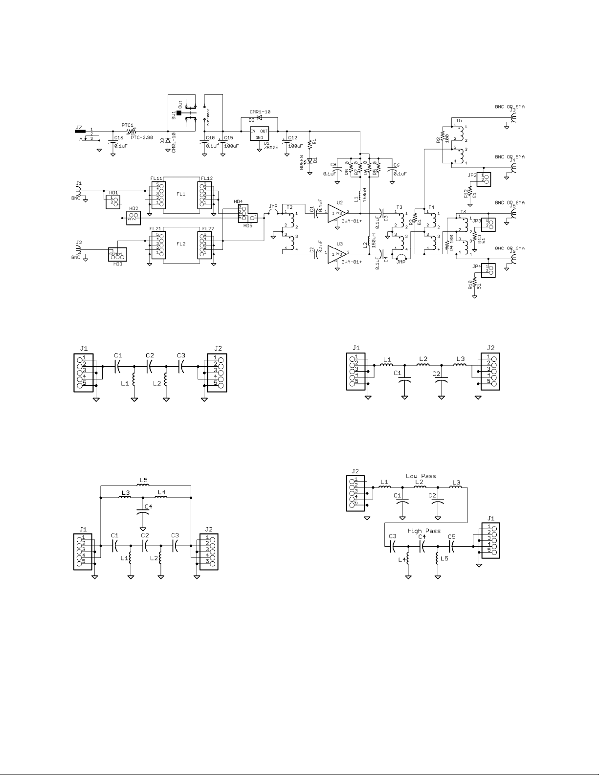
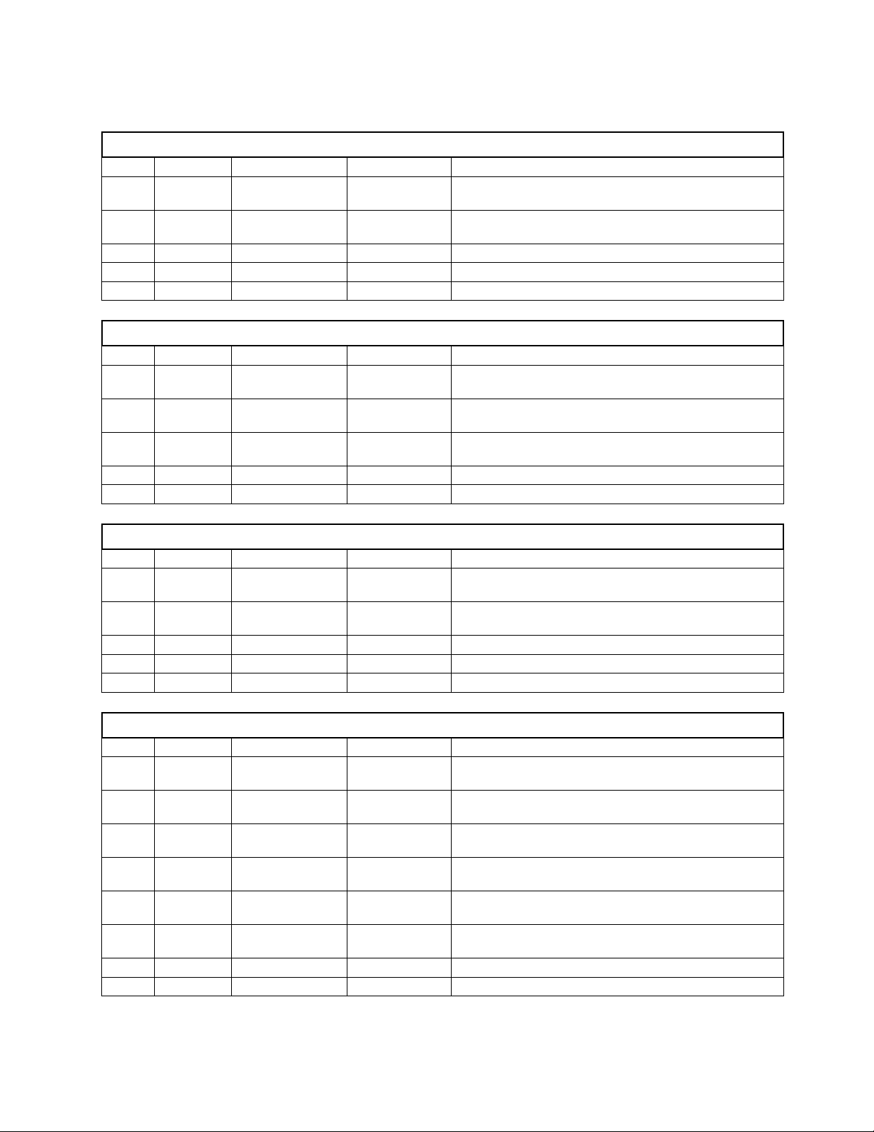
Filter Board Standard Values
862-8504-HP 30MHz High Pass
QTY Part VALUE PN Desc
2 C1, C3 56 F 220-0056 CAPACITOR, MULTILAYER, .1, 50V, 5%, NPO,
56 PF
1 C2 33 F 220-0033 CAPACITOR, MULTILAYER CER., NPO, 5%, 50
V, 33 PF
2 L1, L2 0.27uH 401-2270 INDUCTOR, MOLDED, .3~, 10%, 0.27UH
2 J1, J2 5 PIN SOCKET 612-3105 CONNECTOR, SOCKET, FEMALE, 5 POS, 8504
1 PCB 862-8504-HP
862-8504-HP .7MHz High Pass
QTY Part VALUE PN Desc
2 C1, C3 1000 F 220-1100 CAPACITOR, MULTILAYER, .1, 50V, 10%, X7R,
.001 UF
1 C2 680 F 220-0680 CAPACITOR, MULTILAYER, .1, 50V, 5%, NPO,
680 PF
2 L1, L2 3.9uH 401-3390 INDUCTOR, MOLDED, .3~, 10 %, ORG-WHT-
GLD, 3.9 UH
2 J1, J2 5 PIN SOCKET 612-3105 CONNECTOR, SOCKET, FEMALE, 5 POS, 8504
1 PCB 862-8504-HP
862-8504-LP 30MHz Low Pass
QTY Part VALUE PN Desc
2 C1, C2 100 F 220-0100 CAPACITOR, MULTILAYER. .1, 50V, 5%, NPO,
100 PF
2 L1, L3 0.47uH 401-2470 INDUCTOR, MOLDED, .3~, 10 %, YEL-VIO-
SLVR,0.47 UH
1 L2 0.82uH 401-2820 INDUCTOR, MOLDED, .3~, 10 %, .82 UH
2 J1, J2 5 PIN SOCKET 612-3105 CONNECTOR, SOCKET, FEMALE, 5 POS, 8504
1 PCB 862-8504-LP
862-8504-NC
BCB Notch
QTY Part VALUE PN Desc
2 C1, C3 1000 F 220-1100 CAPACITOR, MULTILAYER, .1, 50V, 10%, X7R,
.001 UF
1 C2 680 F 220-0680 CAPACITOR, MULTILAYER, .1, 50V, 5%, NPO,
680 PF
1 C4 8200 F 220-1820 CAPACITOR, MULITILAYER, .1,50V, 10%, NPO,
.0082 UF
2 L1, L2 3.3uH 401-3330 INDUCTOR, MOLDED, .3~, 10 %, ORG-ORG-
GLD, 3.3 UH
2 L3, L4 27uH 401-4270 INDUCTOR, MOLDED, .3~, 10 %, RED-VIO-BLK,
27 UH
1 L5 100uH 401-5100 INDUCTOR, MOLDED, .3~, 10 %, BRN-BLK-
BRN, 100 UH
2 J1, J2 5 PIN SOCKET 612-3105 CONNECTOR, SOCKET, FEMALE, 5 POS, 8504
1 PCB PCB 862-8504-NC

Band ass Filter
The MFJ-8504-BP is a blank board for use by the customer to roduce custom band ass filters such as
a single Ham Band to limit out of band signals and ossible overload. The board consists of a 5- ole low
ass filter to set the u er limit of signals and a 5- ole high ass filter to set the lower limit of signals.
Programs such as Elsie from Tonne Software (www.tonnesoftware.com) or other on line sources make
calculating the filter values easy. Verification of the filter can be lotted through s ice rograms such as
LT S ice (htt s://www.analog.com/en/design-center/design-tools-and-calculators/lts ice-simulator.html).
The inductors used are a roximately the size of 1/4W resistors and are available from multi le sources.
These should be 5% tolerance.
The ca acitors used should be 5% NPO or COG ty e ca acitors for minimum drift and with a lead
s acing around 0.1 or 0.2 inch. Voltage is not critical.
Suggested arts values for individual Amateur Bands:
Low Pass High Pass
BAND Freq LP L1 C1 L2 C2 L3 FREQ HP C3 L4 C4 L5 C5
160 2 6.8uH 2000pF 10uH 2000pF 6.8uH 1.75 1100pF 3.6uH 750pF 3.6uH 1100pF
80 4.5 3.3uH 1000pF 4.7uH 1000pF 3.3uH 3 560pF 2uH 390pF 2uH 560pF
60 5.8 2.4uH 680pF 3.6uH 680pF 2.4uH 5 360pF 1.3uH 240pF 1.3uH 360pF
40 7.7 1.8uH 510pF 2.7uH 510pF 1.8uH 6.5 300pF 1uH 220pF 1uH 300pF
30 10.7 1.3uH 360pF 1.8uH 360pF 1.3uH 9.5 200pF 0.68uH 130pF 0.68uH 200pF
20 15 0.91uH 240pF 1.3uH 240pF 0.91uH 13 150pF 0.51uH 100pF 0.51uH 150pF
17 19 0.75uH 200pF 1.1uH 200pF 0.75uH 17 110pF 0.39uH 75pF 0.39uH 110pF
15 22.5 0.62uH 180pF 0.91uH 180pF 0.62uH 20 91pF 0.33uH 62pF 0.33uH 91pF
12 26 0.51uH 150pF 0.75uH 150pF 0.51uH 24 75pF 0.27uH 51pF 0.27uH 75pF
10 31 0.43uH 130pF 0.68uH 130pF 0.43uH 27 68pF 0.24uH 47pF 0.24uH 68pF
6 57 0.24uH 68pF 0.36uH 68pF 0.24uH 48 39pF 0.13uH 27pF 0.13uH 39pF

NOTES

FULL 12-MONTH WARRANTY
MFJ Enter rises, Inc. warrants to the original owner of this roduct, if manufactured by MFJ
Enter rises, Inc. and urchased from an authorized dealer or directly from MFJ Enter rises, Inc. to be
free from defects in material and workmanshi for a eriod of 12 months from date of urchase
rovided the following terms of this warranty are satisfied.
1. The purchaser must retain the dated proof-of-purchase (bill of sale, canceled check, credit card or
money order receipt, etc.) describing the product to establish the validity of the warranty claim and submit
the original or machine reproduction of such proof of purchase to MF Enterprises, Inc. at the time of
warranty service. MF Enterprises, Inc. shall have the discretion to deny warranty without dated proof-of-
purchase. Any evidence of alteration, erasure, of forgery shall be cause to void any and all warranty terms
immediately.
2. MF Enterprises, Inc. agrees to repair or replace at MF 's option without charge to the original
owner any defective product provided the product is returned postage prepaid to MF Enterprises, Inc. with
a personal check, cashiers check, or money order. This is good on all products except antennas and software
to cover postage and handling for return from in warranty service. We also take MasterCard, Visa,
American Express, and Discover credit cards. Postage and handling may vary according to the weight of the
product in question. You should specify what type of delivery service you wish. We can send by UPS, U.S.
Postal service or Fedex. MF doesn’t guarantee delivery by US Postal Service.
3. MF Enterprises, Inc. will supply replacement parts free of charge for any MF product under
warranty upon request, provided the following terms are satisfied. MF must receive the original parts you
wish to replace, your proof-of-purchase, and a personal check, cashiers check or money order must be
provided to cover postage and handling. Postage and handling may vary according to the weight of the
product in question. We also take MasterCard, Visa, American Express and Discover credit cards.
4. This warranty is NOT void for owners who attempt to repair defective units. Technical
consultation is available by calling (662) 323-5869.
5. This warranty does not apply to kits sold by or manufactured by MF Enterprises, Inc.
6. Wired and tested PC board products are covered by this warranty provided only the wired and
tested PC board product is returned. Wired and tested PC boards installed in the owner's cabinet or
connected to switches, jacks, or cables, etc. sent to MF Enterprises, Inc. will be returned at the owner's
expense un-repaired.
7. Under no circumstances is MF Enterprises, Inc. liable for consequential damages to person or
property by the use of any MF products.
. Out-of-Warranty Service: MF Enterprises, Inc. will repair any out-of-warranty product
provided the unit is shipped prepaid. All repaired units will be shipped COD to the owner. Repair charges
will be added to the COD fee unless other arrangements are made.
9. This warranty is given in lieu of any other warranty expressed or implied.
10. MF Enterprises, Inc. reserves the right to make changes or improvements in design or
manufacture without incurring any obligation to install such changes upon any of the products previously
manufactured.
11. All MF products to be serviced in-warranty or out-of-warranty should be addressed to MFJ
Enterprises, Inc., 300 Industrial Park Rd, Starkville, Mississippi 39759, USA and must be accompanied
by a letter describing the problem in detail along with a copy of your dated proof-of-purchase and a
telephone number.
12. This warranty gives you specific rights, and you may also have other rights, which vary from state
to state.

Table of contents
Other MFJ Receiver manuals