Page 4
PRELIMINARY CONNECTIONS
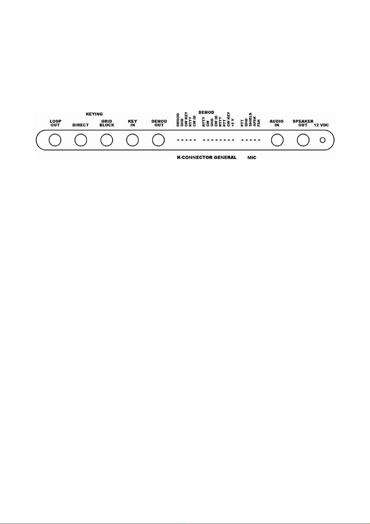
Input an output signals must be TTL level (+5 VDC an groun ). Inputs are RTTY an CW
KEY (RTTY an CW on general purpose connector). There is also a separate CW ID input for i enti-
fying in MORSE while operating RTTY. Outputs are DEMOD (RTTY DEMOD an CW DEMOD on the
GENERAL PURPOSE CONNECTOR) an DIRECT an GRID BLOCK. Connections epen on the type
computer an transceiver use . Either the GENERAL CONNECTOR or the K-CONNECTOR will be
connecte to the computer.
CONNECTIONS
FOR CW For transmission an reception of CW, the following connections are necessary.
1.) A 12 VDC power supply to the POWER jack of the interface.
2.) A shiel e au io cable from the external speaker jack of the transceiver to the AUDIO in jack
of the interface.
3.) If esire , a speaker may be connecte to the SPEAKER out jack of interface.
4.) If the interface is to be use to key the transmitter by han , the key shoul be connecte to
the KEY in jack.
5.) The control cable from the computer to the interface.
6.) A cable from one of the KEY out jacks of the interface to the key in jack of the transceiver. If
you are not sure whether your transceiver requires GRID BLOCK or DIRECT KEYING, try one
an then the other to see which one works. No amage will be one if the wrong one is se-
lecte .
FOR RTTY/ASCII For transmission an reception of RTTY or ASCII signals the following con-
nections are nee e :
1.) A 12 VDC power supply to the POWER jack of the interface.
2.) A shiel e au io cable from the external speaker jack of the transceiver to the AUDIO in jack
of the interface.
3.) If esire , a speaker may be connecte to the SPEAKER out jack of the interface.
4.) The microphone/PTT cable to the transmitter. This cable is supplie with the proper push on
the connector on one en an with the other en unwire . This allows the cable to be con-
necte properly for various types of transmitters. For transmitters that have three wire
microphone connectors, only three of the microphone cable are nee e . AFSK shiel shoul be
connecte to groun , PTT shoul be connecte to PTT OUT an AFSK shoul be connecte to
the AUDIO INPUT. The FSK OUT is not connecte when use for AFSK operation.
Consult the owner's manual for your transceiver to etermine the proper connection of the
MICROPHONE JACK. The white wire is the au io line, the re wire is the PTT line, the black
wire is the PTT groun line, the bare (shiel ) wire is the au io groun an the green
wire is the FSK line.
5.) The control cable from the computer to the interface.
6.) If the interface is to rive a TTY current loop, the TTY shoul be connecte to the LOOP out
jack. The sleeve is the negative si e of your supply. The LOOP OUT pin is usually connecte to
the negative si e of your selector magnets.