MFJ IntelliTuner -991B User manual

INSTRUCTION MANUAL
CAUTION: Read All Instructions Before Operating Equipment
MFJ ENTERPRISES, INC.
300 Industrial Park Road
Starkville, MS 39759 USA
Tel: 662-323-5869 Fax: 662-323-6551
COPYRIGHT 200 MFJ ENTERPRISES, INC.5
C
Model MFJ-991B
VERSION 1A
IntelliTuner
Automatic Antenna Tuner
TM


MFJ-991B IntelliTuner Automatic Antenna Tuner Instruction Manual
©2004-2005 MFJ Enterprises, Inc.
i
Contents
THE BASICS
Introduction...................................................................................................................................... 1
Features............................................................................................................................................ 2
Specifications................................................................................................................................... 2
Fast Start .......................................................................................................................................... 3
Front Panel....................................................................................................................................... 4
SWR/Wattmeter.................................................................................................................. 4
C-UP and C-DN Buttons .................................................................................................... 4
L-UP and L-DN Buttons..................................................................................................... 4
AUTO Button .....................................................................................................................4
TUNE Button...................................................................................................................... 4
POWER Button................................................................................................................... 5
Back Panel ....................................................................................................................................... 6
Power .................................................................................................................................. 6
Remote Port ........................................................................................................................ 6
Radio Interface.................................................................................................................... 6
Transmitter.......................................................................................................................... 7
Ground ................................................................................................................................ 7
Wire .................................................................................................................................... 8
Antenna............................................................................................................................... 8
Installation ....................................................................................................................................... 8
SWR/Wattmeter............................................................................................................................... 9
SETUP
Power Level ..................................................................................................................................... 9
Target SWR ................................................................................................................................... 10
Auto Tune SWR............................................................................................................................. 10
Antenna Memory ........................................................................................................................... 10
Meter Range................................................................................................................................... 11
OPERATION
Manual Tuning............................................................................................................................... 11
Component Limit........................................................................................................................... 12
Foldback Circuit ............................................................................................................................ 12
Tuner Status Indicators .................................................................................................................. 12
Grounding Hints ............................................................................................................................ 14
Antenna System Hints.................................................................................................................... 14
Location ............................................................................................................................ 14
Matching Problems ........................................................................................................... 14

MFJ-991B IntelliTuner Automatic Antenna Tuner Instruction Manual
©2004-2005 MFJ Enterprises, Inc.
ii
APPENDICES
Firmware Version Number ............................................................................................................ 16
Resetting the Tuner........................................................................................................................ 16
Factory Defaults................................................................................................................ 16
Delete Antenna Memory................................................................................................... 17
Total Reset ........................................................................................................................ 17
Self Test ......................................................................................................................................... 17
Power Down Circuit Test............................................................................................................... 18
Relay Test ...................................................................................................................................... 19
Wattmeter Calibration.................................................................................................................... 19
SWR Bridge Calibration ................................................................................................................ 20
Frequency Counter Calibration...................................................................................................... 21
In Case of Difficulty ...................................................................................................................... 21
Technical Assistance...................................................................................................................... 22
List of Accessories......................................................................................................................... 22
Circuit Block Diagram................................................................................................................... 22
FIGURES
Figure 1. Installation Block Diagram.............................................................................................. 3
Figure 2. MFJ-991B Front Panel .................................................................................................... 4
Figure 3. Button Action .................................................................................................................. 5
Figure 4. MFJ-991B Back Panel..................................................................................................... 6
Figure 5. Alinco Interface Cable..................................................................................................... 7
Figure 6. Icom Interface Cable ....................................................................................................... 7
Figure 7. SWR/Wattmeter .............................................................................................................. 9
Figure 8. Power-On Operations .................................................................................................... 16
Figure 9. MFJ-991B Circuit Block Diagram ................................................................................ 22
TABLES
Table 1. Antenna Memory Resolution.......................................................................................... 10
Table 2. Meter Needle Stationary Codes ...................................................................................... 13
Table 3. Meter Needle Bounce Codes .......................................................................................... 13
Table 4. Failure Messages............................................................................................................. 18

MFJ-991B IntelliTuner Automatic Antenna Tuner Instruction Manual
©2004-2005 MFJ Enterprises, Inc.
1
The Basics
Introduction
The MFJ-991B IntelliTunerTM let you rapidly tune antennas automatically: unbalanced or single-wire (or
balanced, with an external balun).
MFJ's exclusive InstantRecallTM, IntelliTuneTM and AdaptiveSearchTM algorithms give you fast automatic
tuning with more than 10,000 non-volatile VirtualAntennaTM memories. There are four banks of memory,
and each memory bank has over 2500 non-volatile memories for tuner settings.
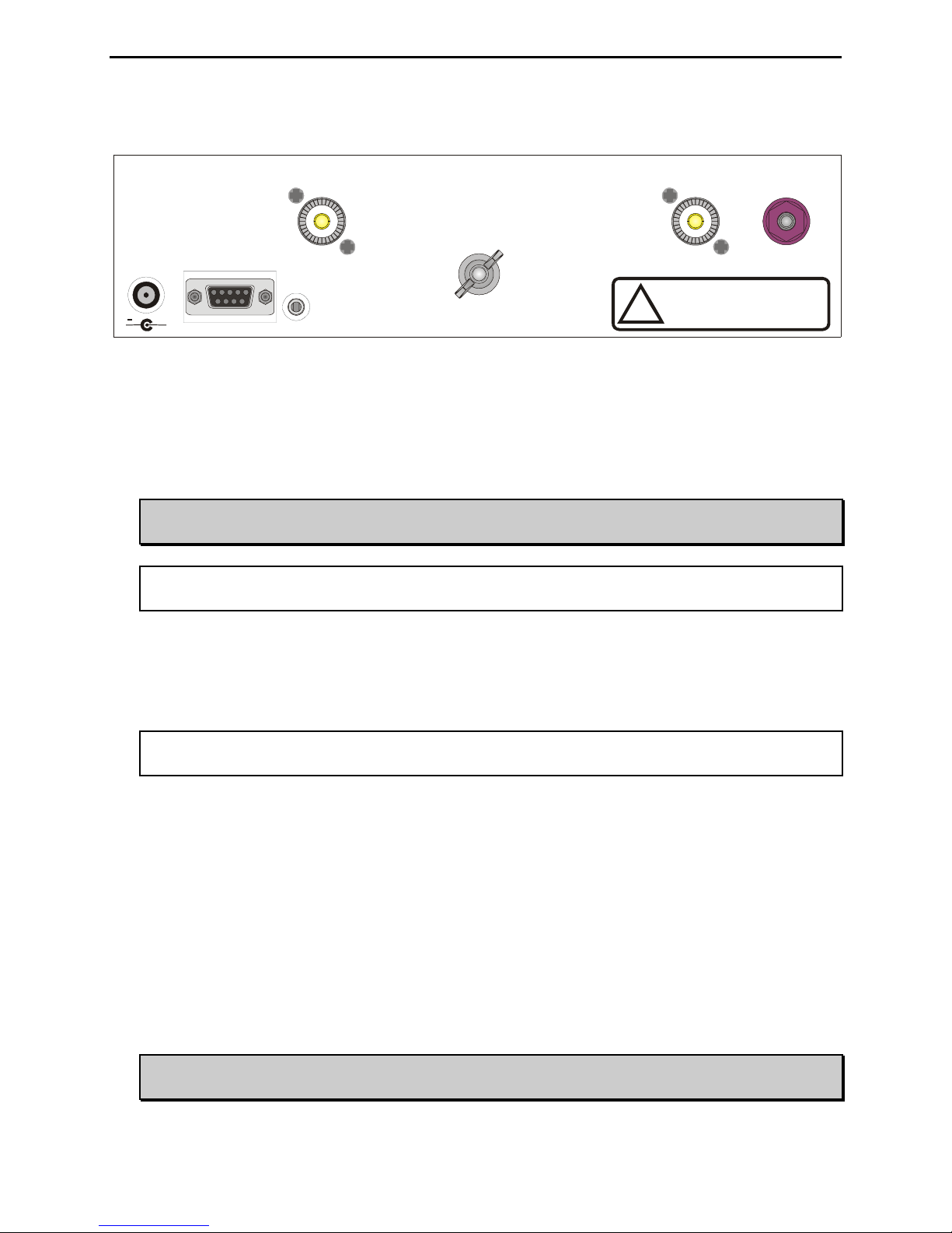
The tuner includes a highly efficient switching L-network with wide matching capability, 1.8 to 30 MHz
coverage, cross-needle power meters, a port for an accessory remote control, a radio interface port, and
heavy-duty 16 amp/1000 volt relays. It is rated at 300 watts to match 6 to 1600 ohms antennas (SWR up
to 32:1) or 150 watts to match a wider range of 6 to 3200 ohms (SWR up to 64:1).
A maximum of 256 values of capacitance and 256 values of inductance are available. With the
inductance switched between the input and output side, this provides a total of 131,072 L/C tuning
combinations. The nominal tuning ranges are 0 to 3900 pF and 0 to 24 μH.
All MFJ IntelliTunersTM learn and remember. When you transmit, they automatically adjust for minimum
SWR and remember the frequency and tuner settings, safely stored in non-volatile memory. The next
time you operate on that frequency (or close to it), these tuner settings are instantly restored and you’re
ready to operate in milliseconds. There are four banks of memory, which can learn and remember more
than 2500 frequencies and tuner settings per bank.
When you key your transmitter, MFJ’s InstantRecallTM checks its memory to see if you have operated
that frequency before. If so, tuning is instantaneous and you’re ready to operate. If not, MFJ’s
IntelliTuneTM algorithm (based on MFJ’s famous SWR Analyzer technology) kicks in. It measures the
complex impedance of your antenna. Next, it calculates the components it needs and instantly snaps them
in. Finally, it fine-tunes to minimize SWR, and you’re ready to operate – all in a fraction of a second.
If the antenna impedance is not within the tuner’s measurement range, MFJ’s AdaptiveSearchTM
algorithm goes into action. Frequency is measured and relevant component values are determined. Only
those values are searched for fast tuning. If it still cannot find a match, the search is performed again
using a different search pattern.
The target SWR can be set at 1.5 or 2.0. The minimum power to tune is approximately five watts. You
can manually tune where you can’t transmit (for listening out of ham bands).
All MFJ’s IntelliTunersTM support radio tuner interfaces that are compatible with Alinco EDX-2 tuner,
Icom AH-3 and AH-4 tuners, Kenwood AT-300 tuner, Yaesu FC-30 tuner, and certain Yaesu radios with
CAT system. Optional interface cables MFJ-5124A (for Alinco), MFJ-5124I (for Icom), MFJ-5124K (for
Kenwood), MFJ-5124Y and MFJ-5124Y2 (for Yaesu) are available from MFJ Enterprises, Inc. The
optional MFJ-993RC Remote Control provides most tuner controls, allowing convenient remote locating
of the tuner itself.
The tuners enter a “sleep” mode when idle and when no transmit signal is present, turning off the
microprocessor clock to avoid the generation of spurious signals.

MFJ-991B IntelliTuner Automatic Antenna Tuner Instruction Manual
©2004-2005 MFJ Enterprises, Inc.
2
Features
• Automatically matches antennas with impedances of 6 to 1600 ohms or 6 to 3200 ohms
• Handles 300 watts (match 6 to 1600 ohms) or 150 watts (match 6 to 3200 ohms)
• Tune in less than 15 seconds, usually less than 5 seconds
• Over 10,000 non-volatile memories for tuner settings
• Four memory banks with over 2500 memories per bank
• Highly efficient switching L-network matching circuit
• 1.8 to 30 MHz continuous frequency coverage
• Selectable target SWR 1.5 or 2.0
• Selectable SWR threshold 0.5, 1.0 or 1.5
• Lighted cross-needle SWR/wattmeter with high, low and auto range options
• Built-in frequency counter
• SO-239 coax fed antenna connector
• Connector for random wire or single wire antennas
• Optional remote control
• Optional radio interface for compatible radios
Specifications
• Impedance matching range: 6 to 1600 ohms (300 watts) or 6 to 3200 ohms (150 watts)
• SWR matching range: up to 8:1 for < 50 ohms and up to 32:1 for > 50 ohms (300 watts)
up to 8:1 for < 50 ohms and up to 64:1 for > 50 ohms (150 watts)
• Minimum power for tuning: 2 watts
• Maximum power while tuning: 100 watts with foldback, 20 watts without foldback
• RF power limit: 300 watts SSB/CW
• Frequency range: 1.8 to 30 MHz continuous coverage
• Frequency counter accuracy: ±1 kHz across HF bands
• Frequency counter range: up to 50 MHz
• Capacitance range: 0 to 3900 pF (256 values)
• Inductance range: 0 to 24 μH (256 values)
• Relay rating: 16 amp 1000 volts
• Relay electrical life: 100,000 operations
• Relay mechanical life: 10 million operations
• Memory endurance: 1 million write cycles
• Memory data retention: > 200 years
• Power requirements: 12 - 15 volts DC, 2.1 × 5.5 mm coaxial plug, center pin positive
• Current consumption: 850 milli-amp or less
• Dimensions (approx.): 10.1 × 2.8 × 9.2 in. (257 × 71 × 234 mm) (width/height/depth)
not including connectors
• Weight (approx.): 3.7 lb (1.68 kg)
† Specifications and design are subject to change without notice.

MFJ-991B IntelliTuner Automatic Antenna Tuner Instruction Manual
©2004-2005 MFJ Enterprises, Inc.
3
Fast Start
WARNINGS
●Never operate the tuner with its cover removed. Contact with the components inside the
tuner while transmitting will result in painful RF burns.
●Locate the tuner so that the rear terminals are not accessible during operation. The single
wire connection may have high voltage while transmitting.
●Disconnect all antennas from the tuner during lightning storms.
●Always tune with low power (about 10 watts). Apply maximum power only after tuning up.
●Never exceed tuner specifications.
●Do not transmit with a high SWR for extended periods of time.
1. Connect the tuner to a 12-15 VDC voltage source capable of supplying at least 850 milli-amp.
2. Connect your transmitter to the TRANSMITTER connector using a 50-ohm coaxial cable.
3. Connect your coax-fed antenna to the ANTENNA connector using a 50-ohm coaxial cable, or
connect your random wire to the WIRE binding post.
4. Connect your ground connection to the GROUND post.
5. Press the [POWER] button to turn on the tuner. Lock the [AUTO] button in to select semi-automatic
mode.
6. Key your transmitter to output a carrier of 10 watts CW, FM or AM.
7. Press and hold the [TUNE] button for one second to start the automatic tuning process. When
completed, check to ensure an SWR of 2.0 or less before increasing RF power.
8. You are ready to transmit.
Note: During the automatic tuning process, the tuner will make some noise. These are the relays
switching at a very fast pace and it is normal operation. Do not be alarmed.
Note: When the tuner power is OFF, the tuner is in bypass mode and RF from the transmitter goes
directly to the antenna with no matching. When the tuner power is ON, pressing [C-DN] and
[L-DN] simultaneously or pressing [TUNE] quickly places the tuner in bypass mode (zero
inductance and zero capacitance) and indicates by the reflected needle bouncing to 20-watt
mark.
Transmitter Automatic
Tuner
50-ohm Coax
Antenna
RF Ground 12 VD
C
Figure 1. Installation Block Diagram.

MFJ-991B IntelliTuner Automatic Antenna Tuner Instruction Manual
©2004-2005 MFJ Enterprises, Inc.
4
Front Panel
MODEL
MFJ-991B
C-UP L-UP AUTO POWER
C-DN L-DN TUNE
AUTOMATIC ANTENNA TUNER
Dual Power Level
300/150 Watts
MFJ IntelliTuner
TM
0
10
30
50
100
200
300
0
5
20
40
60
8
5.0
3.0 2.0
1.5
1.2
Hi x1
Lo x.1
400-3083
1
10
Z
BYPASS
Figure 2. MFJ-991B Front Panel.
• SWR/Wattmeter: The cross-needle meter measures forward power, reflected power, and SWR. It
operates whenever the tuner is power on. Full-scale readings are 300 watts forward and 60 watts
reflected. The meter can be set to low power range of 30 watts forward and 6 watts reflected. The
SWR is measured at the point where the two needles cross. See “SWR/Wattmeter” on page 8 for
more detailed information.
• C-UP and C-DN Buttons: Used to manually increase or decrease the capacitance of the L-network
matching circuit. The capacitance range is 0 to 3900 pF. The upper limit of capacitance, dependent
on frequency, is restricted to limit the maximum voltage and current across the tuner’s components.
Note: Pressing [C-UP] and [C-DN] simultaneously toggles the capacitor between the input
and output sides of the L-network. Forward needle bounces to 30-watt mark when the
capacitor is on the transmitter side. Reflected needle bounces to 5-watt mark when the
capacitor is on the antenna side.
• L-UP and L-DN Buttons: Used to manually increase or decrease the inductance of the L-network
matching circuit. The inductance range is 0 to 24 μH. The upper limit of inductance, dependent on
frequency, is restricted to limit the maximum voltage and current across the tuner’s components.
Note: Pressing [C-DN] and [L-DN] (both DOWN buttons) simultaneously places the tuner in
bypass mode. The reflected needle bouncing to the 20-watt mark indicates this. RF from
the transmitter goes directly to the antenna with no matching.
• AUTO Button: Used to select automatic or semi-automatic tuning mode. Button out selects
automatic mode – the tuning routine is automatically started when at least five watts of power is
applied and the SWR is a preset amount above the preset target SWR. Button in selects the semi-
automatic mode – the tuning routine starts only when the [TUNE] button is pressed.
Note: During the tuning process, the tuner will make some noise. These are the relays
switching at a very fast pace and it is normal operation. Do not be alarmed.
• TUNE Button: Has three different functions based on the length of time you press and hold it before
releasing. Press [TUNE] quickly (less than 0.5 second) to bypass the tuner. RF from the transmitter
goes directly to the antenna with no matching.

MFJ-991B IntelliTuner Automatic Antenna Tuner Instruction Manual
©2004-2005 MFJ Enterprises, Inc.
5
Press and hold [TUNE] for 0.5 to 2 seconds to start the automatic tuning process. The transmitter
must be keyed first with at least five watts of power. When the SWR is already below the target
SWR, pressing [TUNE] will fine-tune the match for a lower SWR, if possible.
“StickyTune” allows for one-handed tuning operation. Normal tuning requires keying the transmitter
with one hand and using the other hand to push the [TUNE] button to start the tuning process. To
toggle the StickyTune mode on and off, press and hold the [TUNE] button for two seconds. The
Reflected Power needle goes to 60-watt mark when on and to 5-watt mark when off. When
StickyTune is enabled, the tuning process starts automatically when the transmitter is keyed with at
least five watts of power regardless of the SWR. This works in both automatic and semi-automatic
modes.
• POWER Button: Used to turn the power on and off. Note that during power-on the analog meter
bounces once to indicate the model 991. When the power is off, the tuner is placed in bypass mode
(straight through from TRANSMITTER to ANTENNA and WIRE). When power is turned on, the
tuner automatically restores all previous settings.
WARNING: Do not turn the power on and off rapidly, otherwise the tuning setting
memory can be corrupted and the unit will have to be reset to factory defaults.
BUTTON ACTION
TUNE C-UP
L-UPTUNE
TUNE L-DN
TUNE C-DN
C-DN L-DN
C-UP C-DN
Press + to switch the capacitor between the input and output side.
Press + to bypass the antenna tuner.
Press + to cycle theAuto Tune SWR among 0.5, 1.0 and 1.5 above the target SWR.
Press + to toggle the Target SWR between 1.5 and 2.0.
Press + to cycle the Memory among banks A, B, C and D.
Press + to cycle the Meter Range among 30 watts, 300 watts and auto range.
Press + to increase both capacitance and inductance.
C-UP L-UP
AUTO
C-UP
L-UP
C-DN
L-DN
TUNE
POWER
Press in to select semi-automatic mode, out to select automatic mode.
Press to decrease inductance.
Press to increase inductance.
Press to decrease capacitance.
Press to increase capacitance.
Press in to turn power on, out to turn power off.
Press less than 0.5 second to bypass the tuner; press and hold for 0.5 to 2 seconds to start the
tuning process; press and hold for more than two seconds to toggle the StickyTune on and off.
Press + to overwrite tuner memory with the current tuner setting.+
TUNE L-DNC-DN
Press + to+ toggle the power level between 300 and 150 watts.
TUNE C-UP L-UP
Figure 3. Button Action.

MFJ-991B IntelliTuner Automatic Antenna Tuner Instruction Manual
©2004-2005 MFJ Enterprises, Inc.
6
Back Panel
RADIO
INTERFACE
+
POWER
12VDC
850mA
REMOTE
PORT
ANTENNA
TRANSMITTER
GROUND
MFJ ENTERPRISES, INC.
STARKVILLE, MS USA
!
Do not connect WIRE and
ANTENNA at same time!
WIRE
Figure 4. MFJ-991B Back Panel.
• Power: This jack accepts a standard 2.1 × 5.5 mm coaxial plug with positive center and negative
sleeve. The tuner requires 12 volts DC at up to 850 milli-amp. The use of a regulated supply is not
mandatory but is recommended for best performance. An optional 12 volts DC 1.5 amp power
supply, the MFJ-1316, is available from MFJ Enterprises, Inc.
WARNING: Do not apply voltages greater than 18 volts to this unit, or permanent damage
to the unit may result.
Note: When the tuner power is OFF, the tuner is in bypass mode and RF from the transmitter
goes directly to the antenna with no matching.
• Remote Port: A female DB-9 connector for connecting to the MFJ-993RC Remote Control,
allowing remote operation of the tuner. The MFJ-993RC duplicates all the front panel buttons except
[POWER]. In addition, there are two LEDs on the remote control. The red Tuning LED lights to
indicate tuning is in progress and the green SWR LED lights when the SWR is below the target SWR.
Note: To use the remote control, the [AUTO] button on the automatic tuner must be locked in;
otherwise, Automatic mode is selected.
• Radio Interface: A 3.5 mm stereo phone jack for connecting to the tuner interface connector of
compatible radios. Most radios provide +13.8 VDC power thought its tuner interface connector. If
separate power supplies are used to power the MFJ-991B, the MFJ-991B should be powered on first
(both needles will bounce) and then turn on the radio, so the radio knows an external tuner is
attached. The radio will disable its internal tuner, if it has one, and use the external tuner.
The Radio Interface works with radios that are compatible with Alinco EDX-2, Icom AH-3 and AH-
4, Kenwood AT-300, Yaesu FC-30, and certain Yaesu radios with CAT system. When connected to
a compatible radio, simply press the [TUNER] or [AT] button on the radio; for certain Yaesu, press
the [TUNE] button on the tuner to start the automatic tuning process. The radio will automatically
switch to CW mode (AM for Yaesu), transmit a 10-watt carrier, and start the tuning process. Once
the automatic tuning is completed, the radio will return to its previous mode and power setting.
WARNING: Make sure the +13.8 volts connection on the radio’s tuner port is capable of
supplying at least 850 mA of current, since the MFJ-991B use up to 850 mA.

MFJ-991B IntelliTuner Automatic Antenna Tuner Instruction Manual
©2004-2005 MFJ Enterprises, Inc.
7
The MFJ-5124A interface cable provides power and control between an Alinco radio and the MFJ
automatic tuner. Supported Alinco radios are DX-70, DX-77, and any Alinco radio that supports the
Alinco EDX-2 tuner.
Pin 3 (Key) connects to the Tip of 3.5 mm Stereo Phone Plug.
Pin 5 (Start) connects to the Ring of 3.5 mm Stereo Phone Plug.
Pin 2 (+13.8V) connects to the Center Pin of Power Plug.
Pin 1 (Ground) connects to the Sleeves of both 3.5 mm Stereo Phone Plug and Power Plug.
Pin 4 is not connected.
Figure 5. Alinco Interface Cable.
The MFJ-5124I interface cable provides power and control between an Icom radio and the MFJ
automatic tuner. Supported Icom radios are IC-706, IC-707, IC-718, IC-725, IC-728, IC-736, IC-738,
IC-746, IC-756, IC-765, IC-775, and any Icom radio that supports the Icom AH-3 and AH-4 tuners.
Push and hold the radio’s [TUNER] button for two seconds to start the tuning process. Push
[TUNER] quickly to bypass the tuner.
Pin 1 (Key) connects to the Tip of 3.5 mm Stereo Phone Plug.
Pin 2 (Start) connects to the Ring of 3.5 mm Stereo Phone Plug.
Pin 3 (+13.8V) connects to the Center Pin of Power Plug.
Pin 4 (Ground) connects to the Sleeves of both 3.5 mm Stereo Phone Plug and Power Plug.
Figure 6. Icom Interface Cable.
The MFJ-5124K interface provides power and control between a Kenwood radio and the MFJ
automatic tuner. Supported Kenwood radios are TS-50S, TS-450S, TS-480HX, TS-570S, TS-690S,
TS-850S, TS-870S, TS-2000, and any Kenwood radio that supports the Kenwood AT-300 tuner.
Push and hold the radio’s [AT TUNE] button for one second to start the tuning process. Push the [AT
TUNE] quickly to bypass the tuner or to cancel tuning in progress.
The MFJ-5124Y interface provides power and control between a Yaesu radio and the MFJ automatic
tuner. Supported Yaesu radios are FT-857, FT-897, and any Yaesu radio that supports the Yaesu FC-
30 tuner—press and hold in the [A](TUNE) key on the radio for one second to initiate automatic
tuning. Supported Yaesu radios are FT-100, FT-857, FT-897, and any Yaesu radio with compatible
CAT system—push the [TUNE] button on the tuner for 0.5 to 2 seconds to start the tuning process.
The MFJ-5124Y2 interface provides control between a Yaesu radio and the MFJ automatic tuner.
Supported Yaesu radios are FT-847 and any Yaesu radio with compatible CAT system. Push the
[TUNE] button on the tuner for 0.5 to 2 seconds to start the tuning process.
• Transmitter: SO-239 connector for coax cable from transmitter or transceiver.
• Ground: Wing-nut terminal for RF ground wire connection.

MFJ-991B IntelliTuner Automatic Antenna Tuner Instruction Manual
©2004-2005 MFJ Enterprises, Inc.
8
• Wire: Binding post for connecting single wire antenna. Notice the WIRE binding post is internally
connected to the ANTENNA connector.
Note: To use the WIRE binding post, make sure to remove the antenna, if any, from the
ANTENNA connector.
• Antenna: SO-239 connector for coax cable from antenna. Notice the ANTENNA connector is
internally connected to the WIRE binding post.
Note: To use the ANTENNA connector, make sure to remove the wire antenna, if any, from the
WIRE binding post.
Installation
WARNING
●Never operate the tuner with its cover removed. Contact with the components inside the
tuner while transmitting will result in painful RF burns.
●Locate the tuner so that the rear terminals are not accessible during operation. The single
wire connection may have high voltage while transmitting.
●Disconnect all antennas from the tuner during lightning storms.
●Always tune with low power (about 10 watts). Apply maximum power only after tuning up.
●Never exceed tuner specifications.
●Do not transmit with a high SWR for extended periods of time.
1. Place the tuner in a convenient location at the operating position. With a random wire antenna the
feed through insulator can have high RF voltage. This voltage can cause serious RF burns if the
terminal is touched when transmitting. Be sure to locate the tuner so this terminal cannot
accidentally be contacted during operation.
2. Connect the tuner to the transmitter with 50-ohm coaxial cable (such as RG-8/U). See Figure 1 on
page 3.
3. Connect the antenna to the tuner as follows:
• Coaxial feedline to the SO-239 connector labeled ANTENNA; or
• Random wire or single wire line antennas should be connected to the WIRE binding post on the
back of the tuner. Note the back panel warning: Do not connect WIRE and ANTENNA at
same time!
Note: Route all single and random wire antennas safely to prevent RF burn hazard.
4. A GROUND post is provided for an RF ground connection. See “Grounding Hints” on page 13.
5. Connect a 12 to 15 VDC power source to the input jack labeled POWER.

MFJ-991B IntelliTuner Automatic Antenna Tuner Instruction Manual
©2004-2005 MFJ Enterprises, Inc.
9
SWR/Wattmeter
The backlit cross-needle meter measures forward power,
reflected power, and SWR, and operates whenever the tuner is
powered on. Forward power up to 300 watts is displayed on the
left-hand FORWARD meter scale. Reflected power up to 60
watts is read on the right-hand REFLECTED meter scale. For
low-power tuning, meter ranges of 30 watts forward and 6 watts
reflected are available. Divide the readings on these scales by
ten when in the low power meter range.
The meter can be set to low, high, or auto range. Auto range
automatically sets the meter scales according to the input RF
power to the tuner. Forward power greater than 30 watts or reflected power greater than six watts
automatically sets the meter to the high power range. Forward power less than 25 watts and reflected
power less than four watts automatically set the meter to the low power range. To cycle the meter range
among low, high, and auto range, press the [TUNE] and [L-DN] buttons simultaneously. The forward
needle will read “300” for high range, “30” for low range, and “100” for auto range until the buttons are
released.
The SWR is read from the eight red SWR curves that range from
1.0 to infinity. The SWR is measured by observing the point
where the forward and reflected power needles cross on the red
curved scales across the center of the meter. No cumbersome or
time-consuming SWR sensitivity adjustments are required with
this meter. Figure 7 shows an SWR of approximately 2.0.
The meter also indicates various operational states of the tuner. Refer to “Tuner Status Indicators” on
page 12 for more details.
Setup
You can set up how the MFJ-991B tuner works and behaves. In addition to displaying power and SWR,
the meter also indicates tuner status when you make setup changes. The meter needles bounce, or rise to
one point and stay, to provide information. In this mode the meters do not indicate power levels. For
example, when you press [C-DN] and [L-DN] simultaneously to place the tuner in bypass mode, the
reflected needle bounces to the 20-watt mark until you release the buttons. Table 2 summarizes the meter
needle stationary and bounce codes.
Power Level
You can set the maximum power level the MFJ-991B can handle to 300 watts or 150 watts SSB/CW.
Power level of 300 watts can match antennas with impedances of 6 to 1600 ohms; power level of 150
watts can match a wider impedance range of 6 to 3200 ohms. Default is 300 watts. Press [TUNE], [C-
UP] and [L-UP] buttons simultaneously to toggle the power level between 300 and 150 watts (Forward
Power meter needle reads 300 and 150 watts, respectively).
0
10
30
50
100
200
300
0
5
20
40
60
8
5.0
3.0 2.0
1.5
1.2
Hi x1
Lo x.1
400-3 083
1
10
Figure 7. SWR/Wattmeter.
reflected power
1forward power
reflected power
1forward power
SWR
+
=
−

MFJ-991B IntelliTuner Automatic Antenna Tuner Instruction Manual
©2004-2005 MFJ Enterprises, Inc.
10
Target SWR
You can set the target SWR to 1.5 or 2.0. The tuning process will stop when a match with an SWR less
than or equal to the target SWR is found. The default is 1.5. Setting the target SWR to 2.0 may require
shorter tuning times. You can toggle the target SWR between 1.5 and 2.0 by pressing [TUNE] and [C-
UP] simultaneously; the meter needles intersect at SWR of 1.5 or 2.0 to indicate the change.
Auto Tune SWR
You can set the SWR threshold to 0.5, 1.0 or 1.5. In the automatic mode, the tuning process will
automatically start when the SWR is above the target SWR by this amount of SWR threshold. For
example, for target SWR of 1.5 and auto tune SWR of 1.0, the tuning process will start whenever the
SWR is above 2.5 (1.5 + 1.0) and there is at least five watts of RF power. Default is 1.0. Press [TUNE]
and [L-UP] simultaneously to cycle the auto tune SWR among 0.5, 1.0 and 1.5 (Reflected Power meter
needle reads 5, 20 and 60 watts, respectively).
Antenna Memory
The “memory resolution” is the width of frequency spectrum that the tuner recognizes as being the same
as a tuned frequency already in memory. The memory resolution is approximately 0.1 percent of the
lower frequency of each amateur band. For example, the memory resolution on the 40-meter band (7000
to 7300 kHz) is 7 kHz; if the tuner has memorized a setting for 7050 kHz, it will automatically call up this
setting for any frequency from 7047 to 7053 kHz. The memory resolutions for the HF amateur bands 160
through 10 meters are:
Meter Frequency Range (kHz) Memory Resolution (kHz)
160 1800 – 2000 2
75/80 3500 – 4000 4
60 5330.5, 5346.5, 5366.5, 5371.5 and 5403.5 5 memory locations
40 7000 – 7300 7
30 10100 – 10150 10
20 14000 – 14350 14
17 18068 – 18168 18
15 21000 – 21450 21
12 24890 – 24990 25
10 28000 – 29700 28
Table 1. Antenna Memory Resolution.
The memory resolution for non-amateur frequency bands between 160 and 10 meters is approximately
0.2 percent of the lower frequency of that band. There are over 2500 memory locations for each of the
four memory banks (A-D). This provides memory for up to four different antennas. Default is memory
bank A. Press both [TUNE] and [C-DN] buttons simultaneously to cycle the memory banks A, B, C and
D (Forward Power meter needle reads 10, 20, 30 and 40 watts, respectively).
Note: Pressing [TUNE], [C-DN] and [L-DN] buttons simultaneously overwrites the tuner memory
with the current tuner setting; settings with SWR greater than 3.0 will not be stored.

MFJ-991B IntelliTuner Automatic Antenna Tuner Instruction Manual
©2004-2005 MFJ Enterprises, Inc.
11
To clear the antenna memory, turn off the power to the tuner, then press and hold both [TUNE] and [C-
DN] buttons while turning on the power. Both meter needles will read half scale, forming a triangle,
asking you to confirm the deletion. Press [C-UP] to confirm delete (both meter needles will read full
scale), or press [L-UP] to cancel the antenna memory delete (both meter needles will read zero).
“Total Reset” erases the antenna memory and returns all tuner settings to their factory default states. To
achieve this, turn power off, press and hold [TUNE], [L-DN] and [C-DN] while turning on the power.
The meter needle readings will be the same as for antenna memory delete: half scale. Press [C-UP] to
confirm total reset (needles go to full scale) or press [L-UP] to cancel total reset (needles go to zero).
Meter Range
You can select a meter scale range or use auto range. In the 30 watts (low) range, the forward full scale is
30 watts and the reflected full scale is 6 watts (divide the meter reading by 10). In the 300 watts (high)
range, the forward full scale is 300 watts and the reflected full scale is 60 watts. Auto range automatically
sets the meter scales according to the input RF power to the tuner. Forward power greater than 30 watts
or reflected power greater than six watts automatically sets the meter to the high power range. Forward
power less than 25 watts and reflected power less than four watts automatically set the meter to the low
power range. Default is 300 watts range.
Press both [TUNE] and [L-DN] buttons simultaneously to cycle the meter range among 30 watts, 300
watts and auto range (Forward Power meter needle reads 30, 300 and 100 watts, respectively).
Operation
Manual Tuning
In certain cases the operator may wish to “touch up” the tuner’s settings. For example, if the target SWR
is set at the default of 1.5, the tuner will stop when a match of 1.5 is found. In all cases, manual tuning
gives the user control of the tuner if desired. Manual tuning is accomplished by using the [C-UP], [C-
DN], [L-UP], and [L-DN] buttons. Since it is not known if more or less capacitance (or inductance) is
needed, manual tuning must be by trial-and-error. Press [C-UP] one time, and the reflected power will
indicate if [C-UP] was the right “direction.” If it was, press [C-UP] again and observe reflected power. If
not, press [C-DN] twice (once to return to the original setting of C, and once for one click past it).
Manual tuning of inductance is similarly accomplished, using [L-UP] and [L-DN]. Since the capacitance
and inductance are interdependent, some back-and-forth between the two may be needed, just as in a
conventional tuner with knobs. Once you are familiar with this process, you will learn how to match
certain antennas and frequencies.
Pressing [C-UP] and [C-DN] buttons simultaneously moves the capacitance back and forth from one side
of the inductance to the other. Factory default is with the capacitance on the transmitter side. To move
the capacitance to the opposite (antenna) side, press [C-UP] and [C-DN] simultaneously. The reflected
needle will bounce to 5-watt mark. Press [C-UP] and [C-DN] simultaneously again to return the
capacitance to the transmitter side (and the forward needle will bounce to 30-watt mark to indicate the
change). A general rule of thumb is that loads with impedance higher than 50 ohms call for the
capacitance on the antenna side; loads lower than 50 ohms call for the capacitance on the transmitter side.

MFJ-991B IntelliTuner Automatic Antenna Tuner Instruction Manual
©2004-2005 MFJ Enterprises, Inc.
12
Pressing [C-DN] and [L-DN] simultaneously or pressing [TUNE] quickly places the tuner in bypass
mode; i.e. zero inductance and zero capacitance. RF from the transmitter goes directly to the antenna
with no matching. The reflected needle bouncing to 20-watt mark indicates changing to bypass mode.
Pressing [TUNE], [C-DN] and [L-DN] simultaneously overwrites the tuner memory with the current
tuner setting; settings with SWR greater than 3.0 will not be stored. Both forward and reflected needles
go to full scale and one beep indicate memory overwrite.
Component Limit
The upper limits of inductance (L) and capacitance (C) are factory-limited according to frequency and
maximum power rating; i.e., higher frequencies need less inductance and less capacitance when the L-
network is properly tuned. Pressing [C-UP] and/or [L-UP] allows capacitance and inductance to be
increased only to these limits. When a selected capacitance or inductance is higher than its allowed limit,
and the frequency is changed, that selection is automatically reduced to the value of its limit. These limits
are used to prevent matching of extreme load impedance outside the tuner’s specification, which may
result in excess voltage and/or current across the tuner’s components.
Foldback Circuit
Modern transceivers with solid-state finals usually have a foldback circuit to protect the final transistors
from high SWR, which can damage or destroy them. A foldback circuit detects the SWR during transmit
and reduces the output power as the SWR rises above a preset threshold, usually 2:1. The higher the
SWR the lower the power is set to prevent damage.
If your transceiver has a foldback circuit, you can simply key down and tune at any power level from 2 to
100 watts. If your transceiver does not have a foldback circuit, you must manually set the power level to
20 watts or less for tuning. At higher power levels, the reflected power occurred during tuning can
damage your transceiver and causes component arcing which can damage the relays in the tuner.
Check your transceiver owner's manual to see if yours has a foldback circuit.
Tuner Status Indicators
In addition to displaying power and SWR, the meter also indicates tuner status. The meter needles
bounce, or rise to one point and stay, to provide information. In this mode the meters do not indicate
power levels. For example, when you press [C-DN] and [L-DN] simultaneously to place the tuner in
bypass mode, the reflected needle bounces to the 20 watts mark until you release the buttons. The
following tables show the meter needle stationary and bounce codes.
If not enough power is applied for tuning (less than 2 watts), the Forward Power needle will bounce to the
100-watt mark. When input power is too high, the tuner enters a self-protection mode and the Forward
Power meter needle bounces to 300-watt mark (full scale). The tuner will not allow any of its relays to
change. This feature is to prevent damage to your tuner.
If too much power is applied when tuning is in progress, the tuner will cease the tuning routine, and the
Forward Power meter needle will bounce to full scale. This occurs when the forward power exceeds 75

MFJ-991B IntelliTuner Automatic Antenna Tuner Instruction Manual
©2004-2005 MFJ Enterprises, Inc.
13
watts and the SWR is greater than 3.0, or when the forward power exceeds 125 watts regardless of the
SWR. If more than 300 watts (or more than150 watts when 150 watts power level is selected) is applied
to the tuner, the tuner will go into bypass mode; both Forward and Reflected meter needles will bounce to
full scale.
Meter Needle Stationary Codes
(Meter needles stay at the indicated mark until buttons are released.)
Forward 30 Watts Mark 100 Watts Mark 300 Watts Mark
[TUNE] + [L-DN] 30 Watts Meter Range Auto Range 300 Watts Meter Range
150 Watts Mark 300 Watts Mark
[TUNE] + [C-UP]
+ [L-UP] Not Used 150 Watts Power Level 300 Watts Power Level
10 Watts Mark 20 Watts Mark 30 Watts Mark 40 Watts Mark
[TUNE] + [C-DN] Memory Bank A Memory Bank B Memory Bank C Memory Bank D
Reflected 5 Watts Mark 20 Watts Mark 60 Watts Mark
[TUNE] + [L-UP] Auto Tune SWR +0.5 Auto Tune SWR +1.0 Auto Tune SWR +1.5
[TUNE] 2 seconds Sticky Tune Off Not Used Sticky Tune On
Both Needles Zero Scale Mid Scale Full Scale
[L-UP] or [C-UP] No (Cancel) Delete Confirmation? Yes (Delete)
[TUNE] + [C-DN]
+ [L-DN] Not Used Not Used Memory Overwrite
Needles Intersect at SWR 1.5 Needles Intersect at SWR 2.0
[TUNE] + [C-UP] Target SWR 1.5 Target SWR 2.0
Table 2. Meter Needle Stationary Codes.
Meter Needle Bounce Codes
(Meter needles bounce to the indicated mark until buttons are released.)
Forward 30 Watts Mark 100 Watts Mark 300 Watts Mark
Capacitor
Switches To
Transmitter Side
Insufficient Power to
Tune
(Forward < 2 Watts)
Power Too High to Tune
(Forward > 125 Watts, or
Forward > 75 Watts and SWR > 3)
Reflected 5 Watts Mark 20 Watts Mark 60 Watts Mark
Capacitor
Switches To
Antenna Side
Bypass Mode
(L = 0 and C = 0)
L or C at Its Limit
During
Manual Adjustment
Both Needles 30/5 Marks 100/20 Marks 300/60 Marks
Not Used Not Used Power Overload
(Forward > 300 or 150 Watts)
Table 3. Meter Needle Bounce Codes.

MFJ-991B IntelliTuner Automatic Antenna Tuner Instruction Manual
©2004-2005 MFJ Enterprises, Inc.
14
Grounding Hints
To minimize RFI, single wire feedlines (such as used with Windom or longwire antennas) should be kept
away from other wiring. Radiation will be minimized if the single wire feeder runs parallel and
reasonably close to the wire that connects the tuner to the outdoor ground. The antenna feed wire should
be adequately insulated to prevent arcing or accidental contact.
CAUTION
For operator safety, a good outside earth ground or water pipe ground should always be
installed and connected to the case of the antenna tuner. Make certain the safety ground also
connects to the transmitter and other station accessories. A wing-nut post marked GROUND is
provided for ground connections.
For safety, please use good DC and RF grounds. It is particularly important to have a good RF ground
when using a single wire feeder. When using a single wire feeder, the tuner needs something to "push"
against in order to force current into the single wire feedline. If a good RF ground is not available, RF
will usually find its way back into the power line (RFI), transmitter audio circuits (RF feedback), or the
operator (RF burns).
Metal water pipes and ground rods provide good DC and AC safety grounds, but they are often
inadequate for RF grounding because they are single conductors. Ground rods by themselves are almost
useless for dependable RF grounding.
RF grounds work much better when "spread out" over a large area, especially when they employ multiple
connections directly to the equipment ground point. Metal water pipes, heating ducts, and fences may
work (especially if they are connected together with multiple wires), but the best RF grounds are radial
systems or multi-wire counterpoises. Radials and counterpoises provide large, low resistance surfaces for
RF energy.
RF and lightning travel on the surface of conductors. Braided or woven conductors have high surface
resistance to lightning and RF. Ground leads for RF and lightning should have wide smooth surfaces.
Avoid the use of woven or braided conductors in RF and lightning grounds unless the lead needs to be
flexible.
Antenna System Hints
Location
For the best performance, an end-fed longwire wire antenna should be at least one quarter-wavelength
long at the operating frequency. Horizontal dipole antennas should be at least a half-wavelength long and
located as high and clear as possible. While good RF grounds help the signal in almost any transmitting
installation, it is extremely important to have good RF grounds with long wire or other Marconi-style
antennas.
Matching Problems
Most matching problems occur when the antenna system presents an extremely high impedance to the
tuner. When the antenna impedance is much lower than the feedline impedance, an odd quarter-

MFJ-991B IntelliTuner Automatic Antenna Tuner Instruction Manual
©2004-2005 MFJ Enterprises, Inc.
15
wavelength feedline converts the low antenna impedance to a very high impedance at the tuner. A similar
problem occurs if the antenna has an extremely high impedance and the transmission line is a multiple of
a half-wavelength. The half-wavelength line repeats the very high antenna impedance at the tuner.
Incorrect feedline and antenna lengths can make an otherwise perfect antenna system very difficult or
impossible to tune.
One example where this problem occurs is on 80 meters when an odd quarter-wave (60 to 70 feet) open
wire line is used to feed a half-wave (100 to 140 feet) dipole. The odd quarter-wave line transforms the
dipole's low impedance to over three thousand ohms at the tuner. This is because the mismatched
feedline is an odd multiple of 1/4 wavelength long. The line inverts (or teeter-totters) the antenna
impedance.
A problem also occurs on 40 meters with this same antenna example. The feedline is now a multiple of a
half-wave (60 to 70 feet) and connects to a full-wave high impedance antenna (100 to 140 feet). The half-
wave line repeats the high antenna impedance at the tuner. The antenna system looks like several
thousand ohms at the tuner on 40 meters.
This places enormous strain on the balun and the insulation in the tuner, since voltages can reach several
thousand volts. This can cause component arcing and heating.
The following suggestions will reduce the difficulty in matching an antenna with a tuner:
• Never center feed a half-wave multi-band antenna with a high impedance feedline that is close to an
odd multiple of a quarter-wave long.
• Never center feed a full-wave antenna with a feedline close to a multiple of a half-wave long.
• If this tuner will not "tune" a multi-band antenna, add or subtract 1/8 wave of feedline (for the band
that won't tune) and try again.
• Never try to load a G5RV or center fed dipole on a band below the half-wave design frequency. If
you want to operate an 80-meter antenna on 160 meters, feed either or both conductors as a longwire
against the station ground.
To avoid problems matching or feeding any dipole antenna with high impedance open wire lines, keep the
lines around these lengths. [The worst possible line lengths are shown in brackets]:
160 meters dipole: 35-60, 170-195 or 210-235 feet [Avoid 130, 260 ft]
80 meters dipole: 34-40, 90-102 or 160-172 feet [Avoid 66, 135, 190 ft]
40 meters dipole: 42-52, 73-83, 112-123 or 145-155 feet [Avoid 32, 64, 96, 128 ft]
Some slight trimming or adding of feedline may be necessary to accommodate the higher bands.
WARNING
To avoid problems, a dipole antenna should be a full half-wave on the lowest band. On 160
meters, an 80 or 40 meter antenna fed the normal way will be extremely reactive, with only a
few ohms of feedpoint resistance. Trying to load an 80 meter half-wave dipole (or shorter)
antenna on 160 meters can be a disaster for both your signal and the tuner. The best way to
operate 160 meters with an 80 or 40 meters antenna is to load either or both feedline wires (in
parallel) as a longwire. The antenna will act like a “T” antenna worked against station ground.

MFJ-991B IntelliTuner Automatic Antenna Tuner Instruction Manual
©2004-2005 MFJ Enterprises, Inc.
16
Appendices
POWER-ON OPERATIONS
(Press and hold buttons while turning on the power.)
Press and hold + + to calibrate the SWR bridge.
Press and hold + to start the self test.
Press and hold + + to reset factory defaults.
TUNE L-DN
Press and hold + + to calibrate the wattmeter.
Press and hold + + to delete the antenna memory.
TUNE C-DN
Press and hold + + + to perform total reset.
TUNE C-DN L-DN
C-UP
Press and hold + to get the firmware version number.
C-DN
Press and hold + to test the relays.
Press and hold + + to calibrate the frequency counter.
L-DN
Press and hold + to test the power-down circuitry.
P
OWER
P
OWER
P
OWER
P
OWER
P
OWER
P
OWER
P
OWER
P
OWER
P
OWER
L-UPC-UP
L-UP
C-UP C-DN
C-DN L-DN
P
OWER
Figure 8. Power-On Operations.
Important: The radio interface cable must be disconnected from the tuner, if the radio power is
off, before performing any of the following power-on operations.
Firmware Version Number
Make sure the meter is calibrated. To obtain the firmware version number, press and hold the [C-UP]
button while turning the power on. The version number X.YY is represented by the meter forward needle
for X (forward reading ÷10) and the reflected needle for YY (reflected reading). For example, forward
needle on 10-watt mark and reflected needle on 20-watt mark represent firmware version number 1.20.
Release button to resume normal operation.
Resetting the Tuner
Each time the tuner is powered off, the microprocessor saves all memories and configurations to non-
volatile memory ready to be used the next time the unit is turned on again. If the tuner is not working
properly, even on initial power on, try resetting to the factory defaults.
Factory Defaults
The unit is shipped with the following default settings:
• Inductance 0 μH
• Capacitance 0 pF on transmitter side
• Power Level 300 watts
Table of contents
Other MFJ Tuner manuals

MFJ
MFJ MFJ-933C User manual

MFJ
MFJ -969 DELUXE Versa Tuner II User manual

MFJ
MFJ MFJ-950K3 User manual

MFJ
MFJ MFJ-949C User manual

MFJ
MFJ MFJ-989C User manual

MFJ
MFJ MFJ-949C User manual

MFJ
MFJ MFJ-926B User manual

MFJ
MFJ MatchMaker 212 User manual

MFJ
MFJ VersaTuner V -989D User manual

MFJ
MFJ MFJ-931 User manual