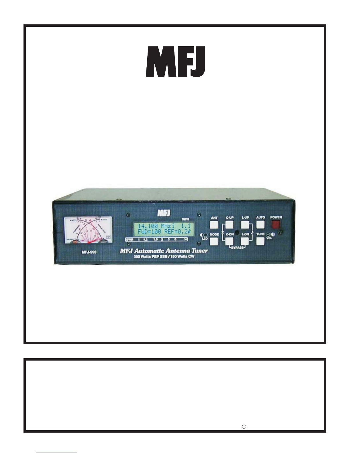
MFJ-993 IntelliTuner Automatic Antenna Tuner Instruction Manual
©2003-2004 MFJ Enterprises, Inc.
ii
LC Limit ........................................................................................................................... 13
Meter Range...................................................................................................................... 13
Setup Mode Menus ........................................................................................................................ 13
Target SWR Menu ............................................................................................................ 13
Auto Tune SWR Menu ..................................................................................................... 14
Meter Range Menu ........................................................................................................... 14
Memory Menu .................................................................................................................. 14
IntelliTune Menu .............................................................................................................. 15
SWR Beep Menu .............................................................................................................. 15
Beep Menu........................................................................................................................ 15
Peak Hold Menu ............................................................................................................... 15
Refresh Menu.................................................................................................................... 15
LC Limit Menu ................................................................................................................. 15
OPERATION
Manual Tuning............................................................................................................................... 16
Meter Codes and Audible Beeps.................................................................................................... 16
Grounding Hints ............................................................................................................................ 18
Antenna System Hints.................................................................................................................... 19
Location ............................................................................................................................ 19
Matching Problems ........................................................................................................... 19
APPENDICES
Resetting the Tuner........................................................................................................................ 21
Factory Defaults................................................................................................................ 21
Delete Antenna Memory................................................................................................... 22
Total Reset ........................................................................................................................ 22
Self Test ......................................................................................................................................... 22
Power Down Circuit Test............................................................................................................... 23
Relay Test ...................................................................................................................................... 24
Firmware Version Number via Meter............................................................................................ 24
Setting the Speaker Volume........................................................................................................... 24
Wattmeter Calibration.................................................................................................................... 25
SWR Bridge Calibration ................................................................................................................ 25
Frequency Counter Calibration...................................................................................................... 26
In Case of Difficulty ...................................................................................................................... 27
Technical Assistance...................................................................................................................... 27
List of Accessories......................................................................................................................... 27
Circuit Block Diagram................................................................................................................... 28
FIGURES
Figure 1. Installation Block Diagram.............................................................................................. 3
Figure 2. MFJ-993 Front Panel....................................................................................................... 4
Figure 3. MFJ-993 Back Panel ....................................................................................................... 6
Figure 4. Alinco Interface Cable..................................................................................................... 7
Figure 5. Icom Interface Cable ....................................................................................................... 7
Figure 6. SWR/Wattmeter .............................................................................................................. 8