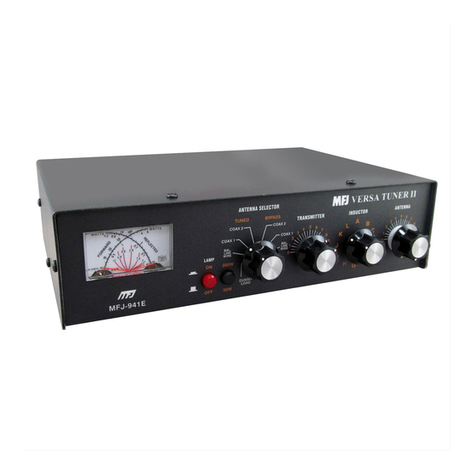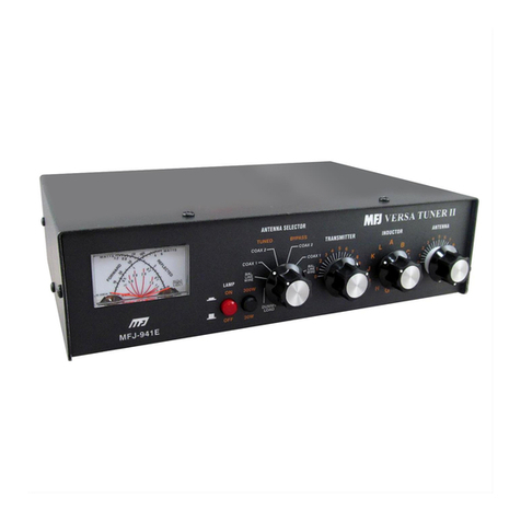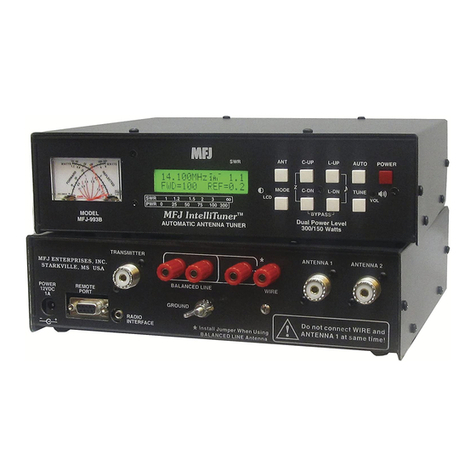
MFJ-9982 2500 Watt Antenna Tuner Instruction Manual
4
A. Coaxial feedlines attach to the connectors labeled COAX 1 and COAX 2 on the rear panel of
the tuner. The ANTENNA SELECTOR switch on the control panel allows the user to select a
DIRECT (bypasses the matching circuit) or a TUNED (includes the matching circuit)
transmitter to antenna connection. The jumper must be placed from the ground terminal to the
bottom balanced line connector as shown in figure 1 above.
B. Random wire or single wire line antennas should be attached using the terminal marked WIRE
on the rear panel of the tuner. The jumper must be placed from the ground terminal to the
bottom balanced line connector as shown in figure 1 above.
Note:Route all single and random wire antennas to prevent RF burn hazard.
C. Balanced feedlines (open wire, twinlead, or twin-axial lines) are connected to the
BALANCED LINE terminals. The jumper from the ground terminal to the bottom balanced
line connector should be removed for balanced line operation.
4. A connection to a suitable earth ground can be made using the ground terminal on the rear of the
tuner. See the section on Grounding Hints later in this manual for ground suggestions.
Operation
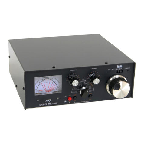
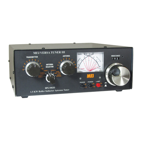
The roller inductor has minimum inductance at about 000 and maximum inductance at about 090 on the
reference counter. The capacitors have maximum capacitance at 0 and minimum capacitance at 10. In
simple language, as the frequency is increased, the normal control positions rotate clockwise just like on
other equipment.
Note:Always use the most capacitance (settings closest to 0) for the most power handling and the least
loss. Use the smallest possible inductance (the smallest number possible) also.
INCREASE the number the roller inductor is set at (on a given frequency) to INCREASE the matching
range. Remember, this LOWERS the efficiency and power handling capability of the tuner. After
making this setting, adjust the capacitors for minimum SWR.
1. Tune the exciter into a dummy load (most solid state transmitters are "pre-tuned" to 50 ohms and do
not require adjusting with the dummy load).
2. Select the desired antenna with the ANTENNA SELECTOR. Remember to set the JUMPER
connection on the rear of the tuner according to the antenna being used. Reference the antenna
connection section of this manual for more details.
3. Position the ANTENNA and TRANSMITTER controls at the settings given in the recommended
tuning chart below:
4. Starting from the minimum INDUCTOR position (highest number), turn the INDUCTOR control
clockwise (adding more inductance) while applying a slight amount of power (less than 25 watts).
Tune for the lowest reflected power and maximum forward power (lowest SWR). The lowest
reading should occur somewhere above the following recommended inductor positions.
5. In this order, adjust the ANTENNA control, INDUCTOR, and TRANSMITTER control for
lowest reflected power (and SWR). Repeat this step a few times until the reflected power is zero.
6. If the SWR did not reach 1:1 in step 5, turn the INDUCTOR control counter clockwise (to a lower
number) again and repeat Step 5. For maximum power handling and efficiency, always adjust the
capacitors to the lowest front panel number (highest capacitance) that allows proper antenna
matching. This insures maximum power handling and lowest power loss in the tuner.
