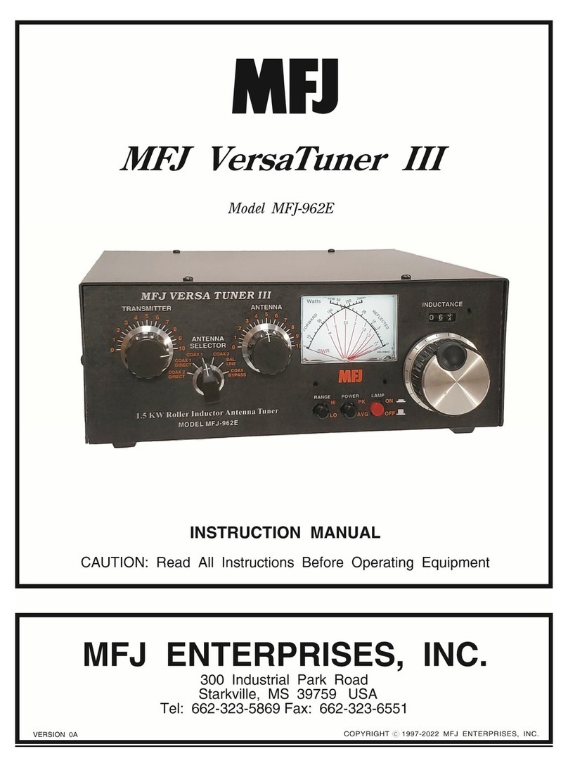
MFJ-986Differential-TTuner Instruction Manual
5
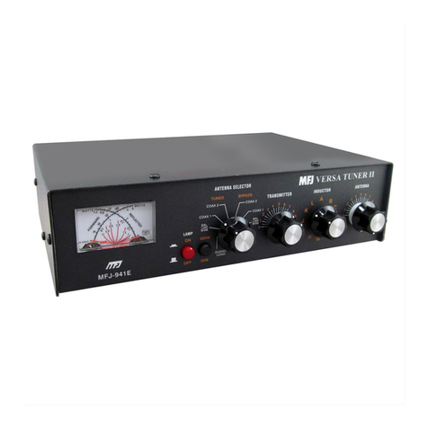
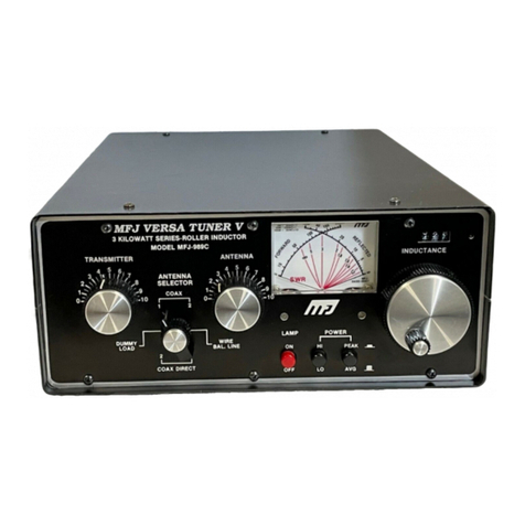
The meter's full scale forward and reflected power range is controlled by the left POWER switch that
selects 2000W (HI) or 200W (LO). If your transmitter runs more than 200 watts of output power, set
this switch to the 2000W HI (in) position. If your transmitter has less than 200 watts of output, set this
switch to the 200W LO switch position (out).
Peak envelope power (PEP) is measured when the PEAK or AVG POWER push button (right-hand
side) in placed in the PEAK (in) position. Peak power and average power values are equal with steady
unmodulated carriers, FSK, or FM. The meter reading on these modes will be the same whether the
PEAK / AVG button is pressed or released. On SSB, the PEP meter reading should be twice the average
power with two tone test modulation.
On SSB, the ratio of PEP to average power varies with different voice characteristics. With most
voices, the PEP reading is three to five times higher than the average voice power reading. The most
accurate peak envelope power readings are obtained only with sustained carrier, voice or two tone test
modulation. During normal voice modulation the wattmeter will typically indicate only 70% of the true
peak envelope power.
Forward power is displayed on the left-hand FORWARD meter scale. This scale is calibrated from 0 to
200 watts and is read directly in the 200 watt position. Each picket (scale mark) represents 5 watts
below 40 watts and 10 watts between 40 and 200 watts.
In the 2000W (HI) position the forward power scale must be multiplied by 10. Each picket represents
50 watts below 400 watts and 100 watts from 400 to 2000 watts.
The reflected power is read on the right-hand REFLECTED meter scale. This scale indicates 50 watts
full scale when the 200W power sensitivity is selected, and 500 watts full scale when the 2000W power
scale is selected. This scale has a picket every watt below 20 watts and every 5 watts above 20 watts.
This scale is also multiplied by 10 when using the 2000W power position.
The most accurate power readings occur in the upper half of the meter scales. When trying to measure
power with a less than perfect match, the reflected power should be subtracted from the forward power
reading.
The SWR is read directly from eleven red SWR curves that range from 1:1 to infinity. SWR is
measured by observing the point where the forward and reflected power needles cross. The SWR is
indicated by the red curve closest to the needle crossing point. No cumbersome or time consuming
SWR sensitivity adjustments are required with this meter.
The wattmeter has an internal lamp that backlights the meter scale. The lamp circuit requires power
from an external 12 Vdc source, such as the optional MFJ-1312B power supply. The rear panel jack
accepts a 2.1 mm coaxial plug with the center conductor positive (+) and the sleeve negative (-). The
negative lead is grounded inside the tuner. The METER LAMP ON / OFF switch turns the meter lamp
off and on.
Antenna Selector
The ANTENNA SELECTOR allows you to select 2 rear panel SO-239 coaxial connectors, either direct
or through the tuner, an external dummy load connection, or a balanced feedline. The External Dummy
Load position lets you connect a dummy load, like the MFJ-250 Oil-filled VERSALOAD or the MFJ-
264 DRY LOAD for tuning.


