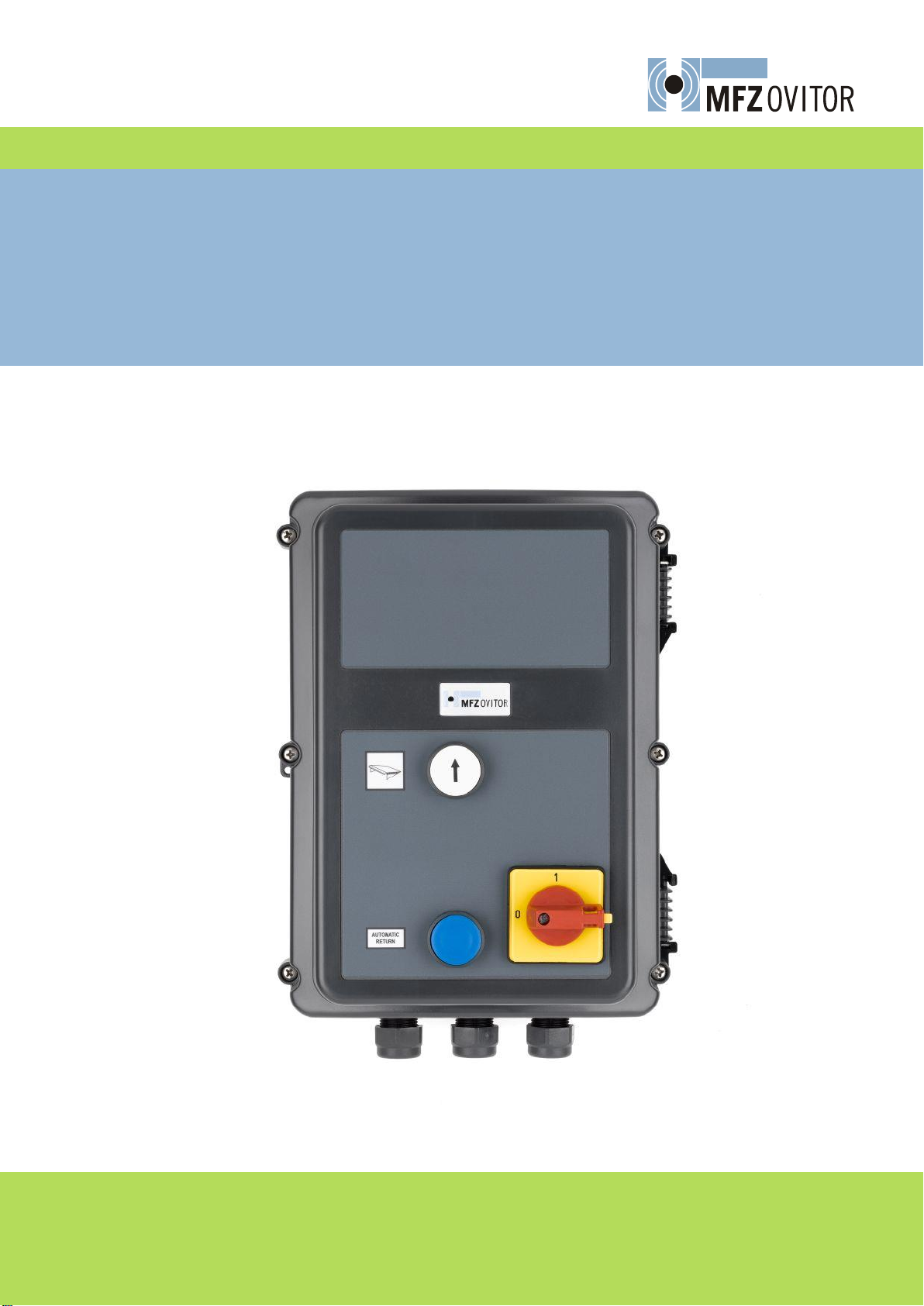
MFZ Ovitor RS 300 K User manual
MFZ Antriebe GmbH & Co. KG
Neue Mühle 4
D-48739 Legden
EN
Operating instructions leveller control RS 300 K

Page 2 / 24 –RS 300 K / Rev.A 05
EN
1 Contents
1 Contents
2 Key to symbols 2
3 General safety instructions 2
4 Overview of products 4
5 Initial operation instructions 6
6 Initial operation 7
7 Functional description 11
8 Further functions 12
9 Option Display 13
10 Error messages and rectification 20
11 Technical Data 21
2 Key to symbols
Danger of personal injury!
The safety instructions must be observed!
Warning! Danger to property!
The safety instructions must be observed!
Information
Special information
OR Reference to other sources of information
3 General safety instructions
Guarantee
The function and safety of the equipment is only guaranteed if the warning and safety
instructions included in these operating instructions are adhered to. MFZ Antriebe GmbH
& Co. KG is not liable for any personal injury or damage to property that occurs as a re-
sult of the warning and safety instructions being disregarded.
Using the equipment for its intended purpose
The RS300K controls are designed only for dock levellers with hinged lip.

RS 300 K / Rev. A 05 - Page 3 / 24
EN
Target group
Only qualified and trained electricians may connect, program and service the controls.
Qualified and trained electricians meet the following requirements:
-knowledge of the general and specific safety and accident prevention regulations,
-knowledge of the relevant electrical regulations,
-trained in the use and care of appropriate safety equipment,
-capable of recognizing the dangers associated with electricity.
Instructions for installation and connection
-The controls must be disconnected from the electricity supply before carrying out
electrical works. It must be ensured that the electricity supply remains disconnected
during the works.
-Local protective regulations must be complied with.
Regulations and bases for testing
For connecting, programming and servicing, the following regulations must be observed
(the list is not exhaustive).
Electromagnetic compatibility
- EN 50014-1
(radio disturbance, household appliances)
- EN 61000-3-2
(disturbances in supply system –harmonic currents)
- EN 61000-3-3
(disturbances in supply system –voltage fluctuations)
- EN 61000-6-2
(electromagnetic compatibility (EMC) –Part 6-2: Generic standards -
immunity for industrial environments)
- EN 61000-6-3
(electromagnetic compatibility (EMC) –Part 6-2: Generic standards -
emission standard for residential, commercial and light-industrial environ-
ments)
Machinery guidelines
- EN 1398
Dock levellers –safety requirements
- EN 60204-1
(safety of machinery, electrical equipment of machines, part 1: general
requirements)
- EN 12100-1
(safety of machinery, basic concepts, general principles for design. Basic
terminology, methodology)
Low voltage
- EN 60335-1
(household and similar electrical appliances - safety)

Page 4 / 24 –RS 300 K / Rev.A 05
EN
4. Housing
Key
Mains switch
Button UP
Button Autoreturn

RS 300 K / Rev. A 05 - Page 5 / 24
EN
4.2 PCB
B1
B2
U
V
W
X2
X1
PE
X6
X3
LED 1
X5
X7
X4
X8
X9
230 400
Key:
X1: terminal block
mains connection
230/400: terminal block
adjustment of mains voltage
PE: terminal block PE
HS1 …HS6: connection mains
switch
X2: terminal block hydraulic
unit
X3: terminal block command
devices
X4: terminal block tube motor
and signal devices
X5: terminal block valves and
door
X6: socket for internal push
buttons
X7: terminal block LCD
X8: terminal block traffic lights
X9: RS485 interface
K1: Contactor
F1 … F3: overload protection
hydraulic unit
F4: Overload protection 24VDC
J1: Jumper phase rotation
Page 6 / 24 –RS 300 K / Rev.A 05
EN
5 Initial Operation –general instructions
Warning!
To guarantee that the equipment functions properly, the following points
must be ensured:
-The dock leveller is installed and operational.
-The command and safety devices are installed and ready for opera-
tion.
-The control housing with the RS300K is installed.
-All motor connections are correct and on the motor side screwed
tight.
Information:
For the installation of the dock leveller, the hydraulic unit and the com-
mand and safety devices, the relevant manufacturer’s instructions are to
be adhered to.
Mains connection
Danger!
To guarantee that the controls function properly, the following points
must be ensured:
- The mains voltage must correspond to the voltage stated on the type
plate.
- For a three-phase current, a clockwise rotating field is required.
- For a three-phase connection, only 3-way automatic circuit breakers
(6A) may be used.
Warning!
After completion of the wiring and prior to switching on for the first time,
the control should be checked that all motor connections are correct and
screwed tight.

RS 300 K / Rev. A 05 - Page 7 / 24
EN
6 Initial Operation
Mains voltage adjustment
A wrong adjustment of the mains
voltage can destroy the control.
Factory setting 400V
400V
230V
Mains supply X1
N L3 L2 L1
PE PE PE
400V 3~/PE
230V 3~/PE
X1
Mains switch
L2'
L2
S3
S4
S1
S2
L1 L1'
S5
S6
L3'
L3
X2 Hydraulic unit
Note rotating field! LED 1 indicates
whether a correct rotational field is
applied. Release can only be
undertaken with a clockwise rotat-
ing field.
U V W
M
PE PE PE
X2
1 2
Emergency stop
U V W
X2
1 2

Page 8 / 24 –RS 300 K / Rev.A 05
EN
Valve:
Y1: stop valve 24 VDC 100%
1 2 3 4 5 6 7 8 9 10 11 12
GND
Y1
X5
Connection to the door control
Door Release: Potential-free contact for
locking the door system. The contact
opens as soon as the dock leveller is not in
the home position.
IMPULSE door close: During operation of
the door leveller the contact is open. Only
when the door leveller is in its home posi-
tion is the contact closed
Interlock door - leveller: The control of
the dock leveller is locked via a potential-
free contact of the door system or a
sensor. The polarity of the signal can be
adjusted. The dock leveller can be
operated only when a release of the door
system is present. If during operation the
door release is removed both traffic light
will turn red.
1 2 3 4 5 6 7 8 9 10 11 12
X3
Interlock
door - leveller
24V
NC contact
1 2 3 4 5 6 7 8 9 10 11 12
X5
STOP
IMPULSE
close
1 2 3 4 5 6 7 8 9 10 11 12
X3
Interlock
door - leveller
24V
black
brown
blue
pnp open
collector
GND GND
24 VDC for external units
max. 250 mA
1 2 3 4 5 6 7 8 9 10 11 12
X5
GND 24V
max. 250mA

RS 300 K / Rev. A 05 - Page 9 / 24
EN
Traffic lights
Inside green light (terminal 2)
Inside red light (terminal 3)
Outside green light (terminal 4)
Outside red light (terminal 5)
Max. load
24VDC max. 100mA
230 VAC max. 40 W
1 2 3 4 5 6
X8
COM
2 3 4 5
COM
24 VDC 12
X5
24V
11
GND
123456
X8
COM
2 3 4 5
COM
230 VAC 1
X4
L1
2
N
Tube motor for shelter door and 230 V
Output
The functions of the 230 VAC output have
to be programmed via the display.
MOD 1: Horn (standard)
MOD 2: Shelter fan
MOD 3: Loading lamp automatic
MOD 4: Loading lamp manual
1 2 3 4 5 6
X4
ÈN L1
Ç N
M
7 8
L1 N
Vehicle detector:
Visual and audible collision safety applied
by an approach sensor. If a vehicle in front
of the gate activates the approach sensor
a warning signal sounds and the lights
outside red turns. Optionally, a door
locking can be activated. This utility must
be activated via the input function.
Wheel block:
The wheel block is used to secure the
vehicle during the loading process. This
utility must be activated via the input
function.
1 2 3 4 5 6 7 8 9 10 11 12
X3
Wheel block
24V
NC contact
Vehicle detector
24V
NC contact
1 2 3 4 5 6 7 8 9 10 11 12
X3
Wheel block
24V
Vehicle detector
black
brown
blue
pnp open
collector
GND GND
24V
black
brown
blue
pnp open
collector

Page 10 / 24 –RS 300 K / Rev.A 05
EN
Free Connection
The operation of the free input can be se-
lected via the input fuction to;
Traffic light confirmation: (NO contact)
The outer green traffic light turns on when
the leveller is retracted, the wheel block is
removed and the reset button has been
pressed.
Safety fence: (NC Contact)
When the security fence is closed the dock
leveller is locked.
Selector switch Shelter
Selector switch for the manual operation of
the dock shelter.
1 2 3 4 5 6 7 8 9 10 11 12
X3
Free connection
24V
Limit switch door leveller
The limit switch indicates that the dock
leveller is in the home position.
1 2 3 4 5 6 7 8 9 10 11 12
X3
Limit switch
24V
NC contact
Cover button connections
All buttons are as No contact to close.
The cover LED (option) has the same func-
tion as the inner green light.
1 2 3 4 5 6 7 8
X6
Dock up
GND 24V
Lip out
LIP in
Dock down
AR
LED

RS 300 K / Rev. A 05 - Page 11 / 24
EN
7 Functional description - Version hinged lip
7.1 Operation of the dock leveller
Raise the dock leveller with the button (dock UP) in dead-man operation mode. When
the dock leveler reaches its upper end position the lip folds out automatically. The button
should be released when the lip is completely folded out. The dock leveller descends au-
tomatically into the loading position (floating position).
With activated current detection, the upper position of the dock leveller is detected (un-
folding of the lip) when lifting from the home position. If the upper end position is not
reach within a minimum of 2 seconds, the control assumes that the lip in not completely
unfolded and lowers the bridge back to its home position. When this position takes long-
er as 2 seconds to be reached, bridge lowers into the floating position.
7.2 Automatic return (AR)
Upon completion of the loading, the dock leveller is returned to its home position by
pressing the AR button.
The AR function expires upon reaching the home position.
AR Version with current control (Standard)
-The dock leveller is raised until the upper end position is reached (this position is rec-
ognized through the current detection or by the time “AR RAISE 1”).
To use the current detection, the time “AR RAISE 1” must be set at a high value.
-The leveller descends for the time “AR DROP 1”
-The leveller is raised again for the time “AR RAISE 2”
-The dock leveller descends automatically to the home position.
-After the interval “AR DROP 2”the leveller will continue with the program sequence.
AR Version timed function:
-The leveller raises for the time “AR RAISE 1”
-The leveller descends for the time “AR DROP 1”
-The leveller is raised again for the time “AR RAISE 2”
-The dock leveller descends automatically to the home position.
-After the interval “AR DROP 2”the leveller will continue with the program sequence.

Page 12 / 24 –RS 300 K / Rev.A 05
EN
8 Further functions
8.1 Protection circuit
The control RS300K has an integrated protection circuit. If an emergency stop signal is
received or the power is interrupted during the operation of the dock leveller, the stop
circuit is switched off and locks the bridge in position.
Only after pressing the lift button can the bridge be moved into its home or floating posi-
tion.
8.2 Detection of the phase rotation
The control RS300K has an integrated circuit for the detection of the phase rotation. The
circuit checks to see if a clockwise rotating field has been applied before allowing a
through connection. Where no clockwise rotating field is detected, then the contactor
does not switch on. Furthermore, the circuit is protected against phase failure. Both of
these errors are signaled by the LED 1.
The Detection of the phase rotation is possible only with the 400V mains supply. If the
mains voltage 230 V 3Phasen should used, then the Detection of the phase rotation must
be deactivated with the Jumper 1.
8.3 Current detection in the folding lip version
The RS300 control has an integrated current measurement for the hydraulic unit. This
measurement allows the detection of the upper end position of the dock leveller.
1. Recognition of the upper end position (unfolding of the lip) when lifting from the
home position.
With activated current detection, the upper position of the dock leveller is detected (un-
folding of the lip) when lifting from the home position. If the upper end position is not
reach within a minimum of 2 seconds, the control assumes that the lip in not completely
unfolded and lowers the bridge back to its home position. When this position takes long-
er as 2 seconds to be reached, bridge lowers into the floating position.
2. Recognition of the upper end position during automatic return
Using “AR RAISE 1” the upper end position is recognized by the current detection or the
set time. After detecting the upper limit position, the bridge lowers automatically to the
home position.
RS 300 K / Rev. A 05 - Page 13 / 24
EN
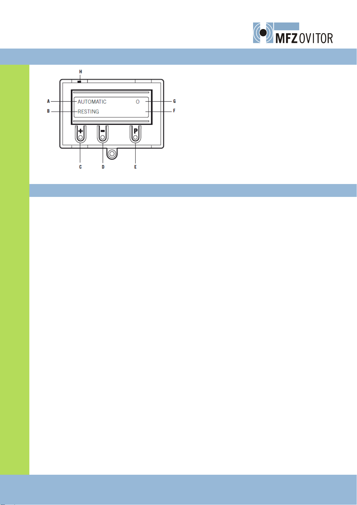
9 Options DISPLAY
Key:
A: Operating mode / Diagnostic info
B: Parameters / Diagnostic info
C: + button
D: - button
E: P button
F: value / status
G: value / status
H: jumper
9.1 Operation mode of the LCD screen
With the LCD screen, the control is provided with 4 operation modes. If the Jumper H is
pulled out, the key buttons +, - and P do not function. The display will continue to func-
tion.
Operation mode 1: AUTOMATIC
The dock is operated in the operation mode AUTOMATIC.
Display: - Notice about the running function
- Notice about the possible errors
Operation mode 2: INPUT
The values of the different parameters can be changed in the operation mode INPUT.
Display: - Notice about selected parameters
- Notice about the set values / status
Operation mode 3: DIAGNOSTIC
Controls specific to the leveller can be examined in the operation mode DIAGNOSTIC.
Display: - Notice about controls
- Notice about the control status
Operation mode 4: MAINTENANCE
MAINTENANCE mode allows the dock leveller to be operated via the installed housing
buttons. The MAINTENANCE mode is only for commissioning. No floating positions are
available.
Display: - Notice about the running functions.

Page 14 / 24 –RS 300 K / Rev.A 05
EN
9.2. Navigator
AUTOMATIC
STANDBY
P- > 1 sec.
INPUT
+ and –> 2 sec.
INPUT
DEUTSCH
Scroll up through menu:
+ > 2 Sec
Scroll down through
menu:
- > 2 sec.
Select value:
P > 1 sec.
Increase value:
+
Decrease value:
-
Save value:
P
Return to INPUT mode:
+ and - > 1 sec.
INPUT
VALVE VER.: 1
INPUT
AR RASIE 1 1.0
INPUT
AR DROP 1 5.0
INPUT
AR RAISE 2 6.0
INPUT
AR DROP 2 2.0
INPUT
TIME HYDR.: 50
INPUT
TRAFFIC LIGHT MOD. 3
INPUT
HORN/LIGHT: MOD 1
INPUT
AUTORETURN: MOD 2
INPUT
WHELL BLOCK: MOD 1
INPUT
VEHICLE SENSOR MOD 1
INPUT
SHELTER: MOD 1
INPUT
SHELTER TIME: 1
INPUT
RELEASE + / - MOD 1
INPUT
RELEASE MOD 1
INPUT
FREE 1 MOD 1
INPUT
CURRENT CTRL 20%
INPUT
DELAY TIME 0%
INPUT
Y1 RAISE 0
RS 300 K / Rev. A 05 - Page 15 / 24
EN
P- > 1 sec.
DIAGNOSIS
.
STOP CHAIN ON
WHELL BLOCK OFF
Scroll up through menu:
+ > 2 sec.
Scroll down through
menu:
- > 2 sec.
Return to AUTOMATIC
mode:
P
Only queries are possible
INTERLOCK ON
HOME LS OFF
ACKOWLEDGE OFF
VEHICLE SENSOR OFF
LIP FORWARD OFF
LIP BACK OFF
RAISE OFF
HOME OFF
DROP ON
CYCLE OFF
P- > 1 sec
MAINTENNACE
.
MANUAL OPERATION OF THE DOCK
LIFT
LOWER (AR)
FORWARD
BACK
P- > 1 sec
Page 16 / 24 –RS 300 K / Rev.A 05
EN
9.3 Operating mode Automatic
Display
Meaning
AUTOMATIC
STANDBY
The dock leveller is in initial position.
AUTOMATIC
FLOATING
The dock leveller is in working position.
AUTOMATIC
EMERGNCY STOP
The dock leveller is in the EMERGENCY STOPS status. For setting the leveller back
into the initial position, the button leveller up must be pressed first and then the
button automatic returns.
AUTOMATIC
ADJUSTMENT
Delay before the leveller is lowering.
AUTOMATIC
RAISE
The dock leveller is raised.
AUTOMATIC
FOLD OUT
The lip is folded out.
AUTOMATIC
AUTORETURN xxx
Automatic return cycle is active.
9.4 Operating mode Diagnosis
DISPLAY
Meaning
Status
STOP CHAIN
Stop circuit, Emergency Stop
ON: circuit closed
OFF: interrupted (fault)
WHEEL BLOCK
Wheel block
ON: activated
OFF: not activated
INTERLOCK
Interlock Door - leveller
ON: activated
OFF: not activated
HOME LS
Limit switch dock leveller
OFF: activated
ON: not activated
ACKOWLEDGE
Acknowledged Traffic lights
ON: activated
OFF: not activated
VEHICLE
Vehicle Sensor
ON: activated
OFF: not activated
LIP-FORWARD
Push button Lip forward
ON: activated
OFF: not activated
LIP-BACK
Push button Lip back
ON: activated
OFF: not activated
RAISE
Push button dock up
ON: activated
OFF: not activated
AR
Push button automatic return
(AR)
ON: activated
OFF: not activated
DROP
Push button drop
(Option)
ON: activated
OFF: not activated
CYCLE
cycle counter
Displays number of leveller cycles

RS 300 K / Rev. A 05 - Page 17 / 24
EN
9.5 Operating mode INPUT
Function
Description
Setting options
Factory setting
DEUTSCH
Select the menu language
DEUTSCH, ENGLISH,
NEDERLANDS
DEUTSCH
Valve version
1: 1 Valve standard
1 Valve
Function
Raise
Lower
Floating mode
Emergency mode
standard
Contactor
1
0
0
0
stop
Y1
1
1
1
0
2: 1 Valve special
1 Valve
Function
Raise
Lower
Floating mode
Emergency mode
special
Contactor
1
0
0
0
stop
Y1
0
1
1
0
3: 2 Valve special
2 Valve
Function
Raise
After Y1 time has elapsed
Lower
Floating mode
Emergency mode
special
Contactor
1
1
0
0
0
Y1
1
0
0
0
0
Y2
0
0
1
1
0
1 … 3
1
AR-RAISE 1
Initial time to raise the dock leveller during
the AR function from the floating position.
0,5 … 25 Sek.
1 Sek.
AR-DROP 1
Time to drop the dock leveler during AR
function to ensure that the lip is folded in
completely before dropping to home posi-
tion.
1 … 5 Sek.
5 Sek.
AR-RAISE 2
Second time to raise the dock leveller dur-
ing AR function..
1 … 20 Sek.
6 Sek.
AR-DROP 2
Time to drop the dock leveller into home
position.
1 … 20 Sek.
2 Sek.
TIME HYDR
Maximum running time of the hydraulic
unit. The watchdog timing of individual
movement serves for the avoidance of
overload due to defect push buttons or de-
fective limit switches.
0 … 254 Sek.
50 Sek.
TRAFFIC LIGHT
MOD
Traffic lights are
MOD 1: no traffic lights
MOD 2: OFF in position home
MOD 3: ON in position home
MOD 1 … MOD 3
MOD 3

Page 18 / 24 –RS 300 K / Rev.A 05
EN
Function
Description
Setting options
Factory setting
Horn/LIGHT
MOD 1: Horn
Produces warning signal, if for example the
wheel block is removed during the loading.
MOD 2: Fan
The fan is necessary for the function shelter
as well as the tubular drive. During the
activation of Shelter, MOD 2 is pre-selected
and cannot be changed.
MOD 3: Dock loading light
After reaching the loading position the light
is switched on and remains on, as long as
to the dock leveler returns to home posi-
tion.
MOD 4:
MOD 1 … MOD 4
MOD 1
AUTORETURN
MOD 1: Autoreturn not active
MOD 2: Autoreturn active
MOD 3: = MOD 2
MOD 4 = MOD 2
MOD 1 … MOD 4
MOD2
WHEEL BLOCK
MOD1: Wheel block not active
MOD2: Wheel block active, with actuation
during loading procedure the red traffic
lights are switched on and the horn signal-
izes this.
MOD3: Wheel block active, with actuation
during loading procedure, all buttons are
blocked.
MOD 1 … MOD 3
MOD1
VEHICLE
SENSOR
MOD 1: vehicle sensor not active
MOD2: Optical and acoustic vehicle detec-
tion.
When a vehicle drives in front of the door
and activates the vehicle sensor, this is
signalized by red traffic lights and the horn.
The dock leveller is released for operation.
MOD3: Optical and acoustic vehicle detec-
tion.
When a vehicle drives in front of the door
and activates the vehicle sensor, this is
signalized by red traffic lights and the horn.
The door (stop contact) is released for op-
eration.
MOD 1 … MOD 3
MOD1

RS 300 K / Rev. A 05 - Page 19 / 24
EN
Function
Description
Setting options
Factory setting
SHELTER
MOD1: not active
MOD2: Controlled via the program.
MOD3: Controlled via the selector switch.
(see free input)
MOD1 … MOD3
MOD 1
SHELTER TIME
The time defines the delay for the release
of the door before the start of the loading
procedure as well as for the release of the
green traffic light outside after the loading
procedure.
0 … 255 Sec.
5 Sec.
RELEASE +/-
MOD 1: NC contact
MOD 2: NO contact
MOD 1, MOD2
MOD1
RELEASE
MOD1: active,
if the door interlock is interrupted during
the loading procedure, the leveller remains
in floating position, both traffic lights switch
to red, the buttons are locked and hydraulic
unit is switched off.
MOD2: active,
if the door interlock is interrupted during
the loading procedure, the leveller remains
in floating position, both traffic lights switch
to red.
MOD1, MOD2
MOD1
FREE INPUT
MOD 1: not active
MOD 2: Traffic light acknowledge
MOD 3: safety fence
MOD 4: Selector switch shelter
MOD 5: only for telescopic lip
MOD1 … MOD 5
MOD1
Current control
threshold
The value of the current control represents
the increased height of the current of the
hydraulic unit with the impact into an end
position. This parameter must be adapted
to the respective unit.
0= off
0% … 35 %
in percent
20%
Time Base
With this parameter different speeds of the
telescopic lip can be adapted when drawing
in and driving out. A negative value must
be selected, if the lip is faster drawn in than
driven out.
- 50 % … 50%
0%
Y1 Raise (Visi-
ble only when
mode value =
3)
After the set time value 1 (Y1) will the dock
leveller extend.
0,1 … 25,0
0

Page 20 / 24 –RS 300 K / Rev.A 05
EN
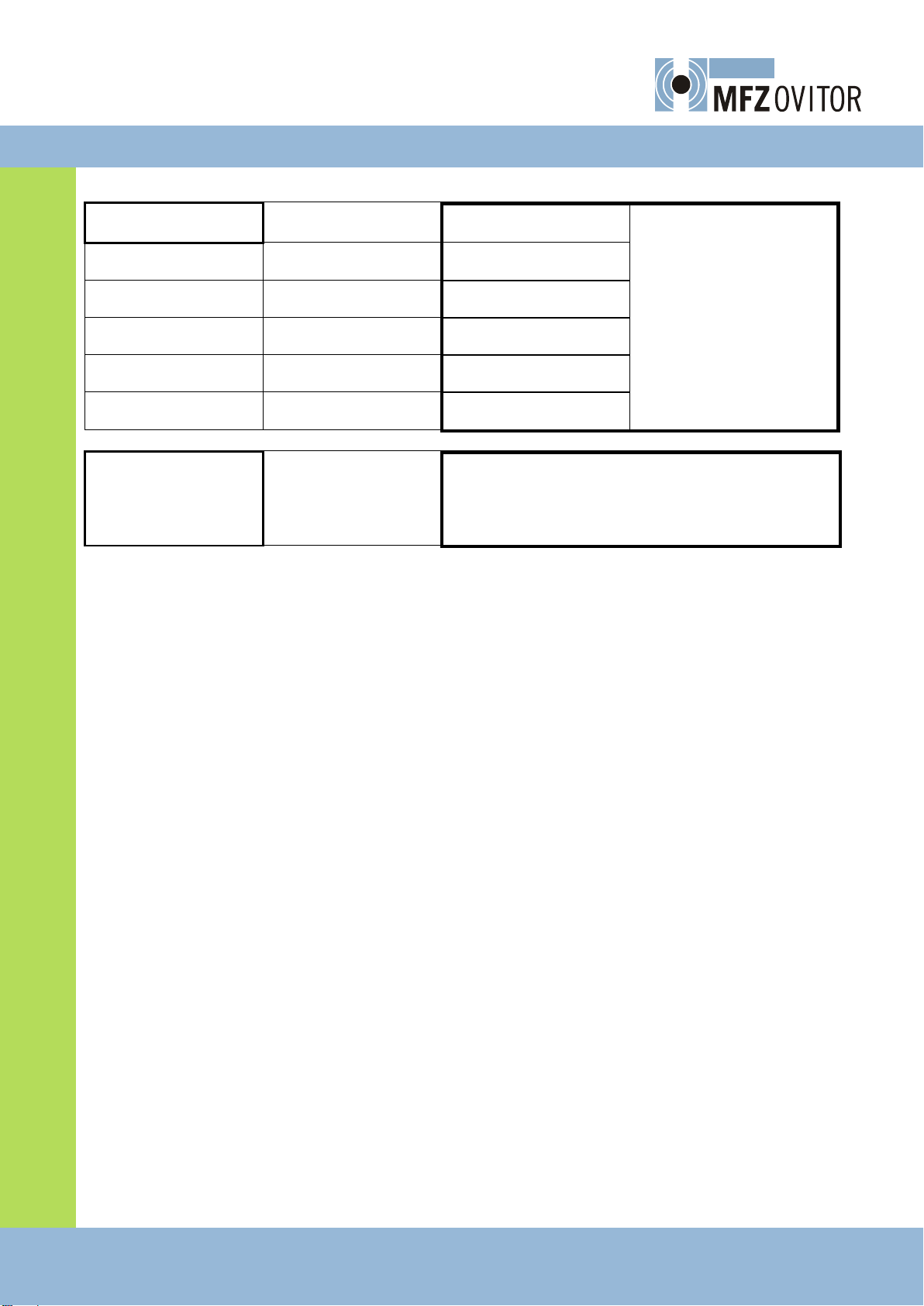
10. Error messages and rectification
Error messages
Cause
Rectification
System does not respond
No mains power
Check mains power to control box
Leveller is not rising when
the UP button is operated.
interlock door –leveller is
activated
Check interlock contact
Leveller is not raising when
the UP button is operated,
although motor is running,
the red LED is out
Connection of the hydrau-
lic unit is wrong
Swap two phase wires of the hydrau-
lic unit
Red LED ON
Fuse defectively or phase
is missing or to rotary
field of the mains supply
is wrong
Check hydraulic unit, cabling and
fuses
Error message Display / Op-
tion
Cause
Rectification
ERROR HY ZEIT
The programmed running time
been exceeded
Check buttons and cabling.
Re-programme the running time
ERROR ROT:FIELD
An incorrect rotating field is
connected to terminal X1
Ensure that a clockwise rotating field is
connected
EMERGENCY STOP
Emergency stop circle opened
or voltage failure during unde-
fined position
- check emergency stop circuit
- use the button up and AR to bring the
leveller into the initial position.
INTERLOCK
interlock door –leveller is
activated
Check interlock contact
Table of contents
Popular Control Unit manuals by other brands

claber
claber 90826 user manual

Sawo
Sawo STAINLESS STEEL TOUCH CONTROL manual

H3C
H3C SFP-GE-SX-MM850-A manual

Siemens
Siemens SIMATIC ET 200S Original operating instructions

Blake Water Solutions
Blake Water Solutions MOD-EMU-BWS Operation & installation instructions

Regent Lighting Solutions
Regent Lighting Solutions Miso installation instructions


