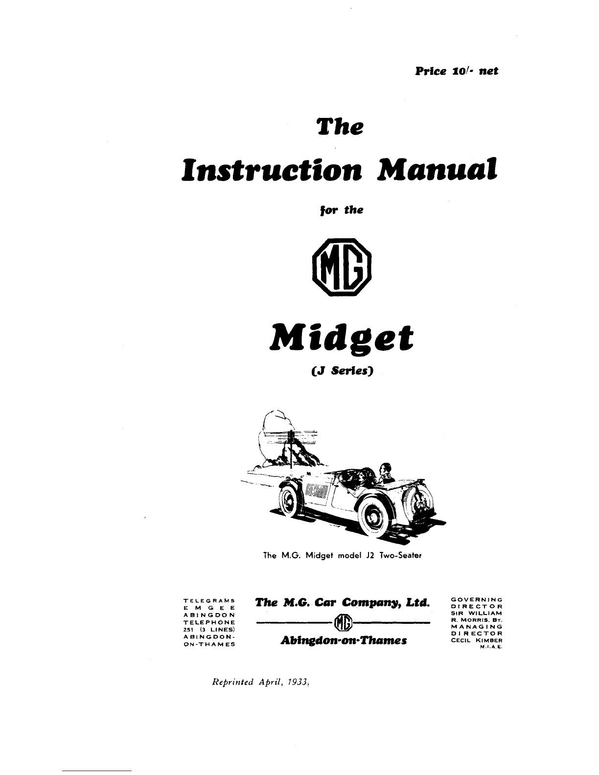
MG Midget J1 1933 User manual

The
Instruction
Manual
Midget
(J
Series]

Price
f0l-
net
The
Instruction Manual
for
the
Midget
The
M.G.
Midget
model
J2
Two-Seater
TELEGRAMS
EMGEE
The
M.G.
Cm Company, Ltd.
zP,V:R,N,',N:
ABINGDON SIR WlLLlAM
TELEPHONE R. MORRIS.
BT.
251
(3
LINES)
MANAGING
ABINGDON- D1RECTOR
ON-THAMES
Abingdon-on-Thrrmes
cEclL K~MBER
M
I.*
E.

CAR NO.
I-1
TELECRAMS:
EMCEE
ABINCDON.
PHOllt: lBlYCDOW
251.
ANY QUESTION
AFFECTING
THE CUARANTEE ATTACHED
TO THIS CAR TO BE REFERRED [VIA THE ACENT FROM
1
WHOM THE CAR WAS PURCHASED] TO THE MANUFACTURERS
The
M.G.Car
Company
L?
Abingdon-on-Thames
CHANGE OIL COMPLETELV EVERV
1500
MILES.
GUARANTEE
CEASES
ON
REMOVAL
OF
THIS
PLATE.

Chassis
No
.............................................................................
Must be quoted
1
in
a11
Engine
No.
!
oorrsspondenoe
...........................
Owner
:

IMPORTANT
HE
attention of owners of new
..G.
Midget Sports cars is
drawn to the following.
The importance of carefully
running-in a new engine cannot
be over-estimated, and care and
restraint during the first 2,000
miles will be handsomely repaid.
Change the engine oil after the
first 500 miles, and every 1,OOr-
1,500 miles thereafter.

INDEX
I.
URRICATION
...
... ...
Approv'ed Engine oils
...
...
...
...
...
Engine lubrication
...
...
...
...
Dynamo lubrication
...
...
...
...
The Distributor
...
...
...
...
Contact break'er
...
.
.
Chassis Lubrication Chart will be found at the end of
the Manual
...
...
...
...
GENERAL SURVEY
...
...
...
...
Steering
...
...
...
...
Brakes
...
...
...
...
Engine
... ...
...
Engine bearings
...
...
...
...
Shock absorbers
...
...
...
...
...
Ignition
...
...
...
Th.e
Oil
Restrictor
...
...
...
...
Clutch thrust
...
...
Gmearbox and back axle
...
...
...
...
...
Clutch
...
...
...
...
Differ'ential
...
Universal joint and propeller shaft
...
...
Suspension
...
Carburetters
Sliding roof on Saloons
...
Front fairing
Tool locker
...
Tools
Tyres
.
.
ADJUSTMENTS
...
Brake adjustment
...
Decarbonising
...
Removing valves
Grinding-in valv.es
Reassembling valv'es
Replacing camshaft
...
Adjusting rockers
Replacing cylinder head
...
Rocker clearance
Clutch adjustment
...
Steering adjustment (gearbox)
...
Fitting drop arm
...
...
Engine dismantl.em'ent
...
Timing dismantlement
...
Draining the sump

Axle disnl:~ntlen~ent
.
.
...
...
Removing the dynamo
...
'I'he detection and remedy of ignition f;rults
.
... ...
l'ngine will not fire
...
...
...
Misfiring :~ndhad starting
...
...
Iicpl:~cenlcntof lamp bulbs
...
...
...
Carburetters
...
...
Carburetter synchronising
...
Tyre pressure
... ...
...
...
...
...
Removing tyres
.
.
...
I)yn:~mo
...
13rushes
...
Conlmutator
Dynamo field fuse
'Third brush regulator
...
Starter motor
...
Battery
...
Ammeter
F
11
ses
...
The
Cut-out
...
Distributor
Coil
CVarinng lamp
..
...
Headlamps
Side lamps and tail I:~nlp
...
Horn
...
Petrol pump
...
Wiring diagrams
...
52
...
53
...
54
...
54
...
56
...
56
...
57
...
S8
...
58
...
58
59
...
60
...
60
...
61
...
62
...
62
...
63
facing page
49
'I'he lista of
M.G.
Agents. Radi:ltor Repair Service Ilepots. 13ucas Agents.
:Ire to he found at the end of the Manual
.

FOREWORD.
PAGE
ONE

IJAGE
TWO

The
Manual
of
the
M.G.
Midget
The first thing that the owner will want to know concerning his Car will
be the various lubricants that are recommended by the makers and the points
of
the chassis that require attention. The engine
oil
filler is situated on the
off
side
of
the engine alongside which there is a dip stick.
Under no circum-
stances should the Car be driven fast on the lower gears or exceeding35 miles
an hour on top gear during the first 500 miles.
At
the end
of
this period the
engine
oil
should be drained and the base chamber refilled with new
oil.
The
oil
filter which will be refcrred to later should be removed and washed out
with petrol, this should be again attended to after the first
1,000
miles and
every subseq~~ent
1,000
miles.
It is inadvisable to run
:I
cold engine fast until the
oil
has had an
opportunity
of
circulriting and warming up aufficientl!. in order to circulate
freely through the
oil
passage ways throughout the engine. The pump is
called upon to suck from the base chamber or sump,
oil
which has become
thick with standing, particularly in cold weather. It may be noticed that
the
oil
gauge will show that the pressure drops as the speed increases if the
engine is driven at all fast when cold. This is an indication that the
oil
has
not become sufficiently thin to pass into the pump in suficient quantity and
the speed
of
the Car therefore should be kept down until such a time as the
r
>
oil
pressure remains constant.
I
he pump lubric:~testhe wholc
of
the engine
including the valve gear. Upper cylinder lubricant is recommended during
th'e running in period, and should be added to the fuel in the quantity
recommended by the manufacturers.
A
list
of
these oils is given on page
5.
J/A
PAGE THREE

It is just
:1b
in~portantnhen warnling up the cncinc not to allo\\~it to tick
o\Tertoo slo\\'ly (:ipprosini:~tely,
1,000
r.p.m. is the hest w:~rniingup engine
speed), as this will pre\ ent the qlinder \\:ills being properly luhricnted owing
to thickness of the oil, :ilso do not use the choke :Iny IonQcr than necessary.
,
.
I
he gearhos and rear :~xleare provided
n
it11 hes:iQon shape upssituated
in such a manner that they :~utonintic:~Il)indicate the height level to which
oil
should he filled, :~ndprevent the possibility of over filling. It should he
renicmhercd that the Car should not he n~ovcdin :In!. \\.:~y \vhen the gear
box and hack axle :Ire being filled, otherwise additional luhric:~nt may be
carried round
by
the teeth
of
the gears thus causing the housing to contain
more
oil
than they need and above the proper level.
@
REAR
BRAKE
CABLE
@FRONT
BRAKE
CABLE
v
a.
-
SUPPORT
Chassis fittings :Ire conveniently lubricated from
A
oil
nipples,
3
on either
side
of
the Car, which are to he found
on
the brackets supportiiig the dash-
hoard. The bonnet has to be lifted and the nipples fed
by
the
oiP
gun
provided with the Car. Reference to the pl:~tes:~tt:~chedto the dash-board
show that on the
off
side
of
the C:lr there are nipples n~:~rked
A,
H
and
C
and
on the near side
of
the C:lr nipples
D,
1'
and
F.
'l'he points luhricated by
these various nipples are the hr;tke cables, the spring trunnions, the steering
box and colunln and the bnke cross shaft. 'l'he hrake opcr:~tingspindles
which pass through the hrake drums are separately lubricated
:IS
also are the
steering head pins and the track rod and other steering hall socket joints.
Only use Shell gear oil in the oil gun.
PAGE
FOUR
J
/A

A
lubricating chart is provided at the end of the book indicating the
lubrication that is carried out from the central dash-board nipples and is
shown in black and the other points on the Chassis that have to he individually
lubricated are shown with a red circle surrounding them, and
if
there is any
doubt in any owner's mind as to the exact location of the nipples, they can
be seen in one or more of the illustrations of the parts contained in this
manual.
'The following lubricants are recommended by the Company
:
Approved Engine Oils.
Everv M.G. Midget is tested on AeroShell and
the sump and spare tin are filled with the same brand when the car is issued
new. W,e very strongly recommend the use of this oil, as we have found it
most satisfactory under the most arduous racing conditions.
On the rare occasions when AeroShell cannot be obtained the following
is the list of Oils approved for use
:-
Shell Triple (summer and winter).
Castrol
XI,
(winter), XXI, (summer).
Uuckham's Adcol
NP2
(winter), NI'3 (summer).
Sports
"
Filtrate
"
(regd.) (summer and winter).
Mobiloil
"
AF
"
(\\inter),
"
D
"
(summer).
Morrisol (summer and winter).
I'r;~tts'He:~vy(summer and winter).
I'rice's Motorine
"
C
"
de 1,uxe (summer :~nd\\inter).
Speedolene
"
13
"
(summer and winter).
Sternol
WW
Heavy (summer and winter).
Gearbox and Back Axle.-As
in the case of engine oils, we ;llso append
the following list as approved for use in the gearbox and back axle
:
-
Gcarhov
ant1
Back
Aslc.
Shell Gear Oil.
Castrol Gear Oil.
I)uckham1s Ge:lr
Oil
"
N."
Filtrate Gear
Oil
(regd.).
Mobiloil
"
C."
(Mobiloil
"
Cif'
"
for gearbox in \\inter).
t'ratts' Gear Oil.
Price's Motorine Amber
"
R."
SpeedoIene
"
H."
Stern01 Liquid Ambroleum.
Upper Cylinder and Supercharger Vane Lubricants.
Shell Ilpper Cylinder 1,ubric:lnt.
Castrollo.
Gargoyle Ilpper Cylinder I>ubricant.
Mixtrol.
and under no circumstances must a mineral and vegetable base oil be mixed
in the engine.
Great care should b,eexercised in mixing oils at all, and
it
is far prcferable
if
anybody wishes to run on a particular oil or is sop forced by circumstances,
that the old oil should be drained out first :~nda completc
replenishment
made.
[Tnder no circumstances should paraffin be used to wash out the lubric-
ating system unless the engine is being dismantled. More detailed instruction
of the lubricating system of the engine will be found on p:~ges37-40 which
J/A
PAGE
FIVE

deals with the complete travel of the oil from the sump to the pump, thence
through the various pipes and passnges in the engine to
the
main 2nd big
end benrings and to the overhead valve gear. The oil pump is provided with
a relief valve of very simple construction consisting of a spring and dash-pot
enclosed in a cover plug. The details of this will also be found on page
38.
We will now leave the general lubrication summary with the advice to
only use recommended oils whenever obtainable.
Five gallon drums can
always he supplied by :~ccrcditedAgents, and this is by far the cheapest
way of buying oil. Keep the receptacle that is used for filling clean
and covered, :~ndalso wash around back axle and gear box filler
caps before these :Ire unscrewed.
The Engine, gearbox, and back axle should
preferably be drained prior to refilling after the Car has been running some
time, so that the lubricant has had a chance to become fluid.
General Survey.
Immediately after taking delivery of the car
it
is
advisable to become familiar with its general mechanical details and in order
to assist as mucli
;IS
possible
it
has been thought advisable to give a brief
pictorial survey.
Figure
2.-LJndcrnc;1tli \it,\\.
of
[hc
3l.t;.
Midget chassis, sho\\.ing
rhc
Burgess silencer and
the
ribbed Elclctron
sump.
The view shown in Illustration No.
3
is perhaps
:I
little unconventional
to sonle people, but
it
is the view obtained by looking
nt
a chassis from under-
r.
nenth.
I
he batteries and petrol tank are not in position, but the under
shield bene:~ththe ge:ir box and front passenger's compartment can be seen.
Certain views taken from below will be described later, more particularly
the front nnd rear axles.
The engine suspension is three point, the single or front point being
mounted in the centre of the front cross member of the chassis. The nose
piece of the engine is fitted into the cross member by means of
:I
split bearing
into which is fitted
a
rubher bush. This nose piece hns two brackets, one on
either side, on to which the radiator is fixed by means of two studs.
The underslung chassis frame is of unusual design having an extremely
low centre of gravity, the main principles of which having already been tested
and brought to perfection in competition work and racing.
PAGE
SIX
J/A

Figure
3
is a rear end view of the chassis and shows the back axle attached
to the springs
by
long
"
U
"
bolts and a spacer, the mounting of the shock
absorbers, the rear cover to the back axle with its filler cap, antl the cradle for
the battery. The rear cross member has extensions on either side in which
the rear end of the rear springs are located.
9
PETROL
PIPES
Figure
3.-R(.:rr
vie*\\,
(IT
chasqis with Ixlltrari(,s rrmovc.~l from cradl~,b\~owingposition
of
shock :~l)sc~rhr.rsantl prlrol fwd pipr~.;cm
~hr
J
I
ch;~ssis(+-s(.;~lr'r:rnd Snlonrttv).
Illustration
No.
4 shows the location of the Petrol Tank in relation to
the pipe lines on the 4-Seater and Salonette Models, hut in point of fact on
these Models the P,etrol Tank is actually supported in the Body.
Figure
4.-Sectitrn:~l view of petrc~ltank, showing main :~ndrc.crvl,
fw~lpip(,.;, leaving on(. gallon for rcst2rvc
on
the
J
I
ch:~ssis.
Figure 4.A shows the Petrol Tank on the 2-Seater Model having a capacity
of 12 gallons, lenving
3
gallons for reserve. The Petrol Tap is at the top of
the Tank in
a
position which is easily accessible from the driver's seat, and
is suitably marked
to
indicate the desired position of the Lever.
JIG
PAGE
SEVEN

Figure
5
may need a little exp1:lnation.
It
cont;lins
:I
close up view of
the rear of the chnssis as well as a view taken of the spring anchorage and
shock absorber bracket as seen from beneath the Car. The springs ane held
in position by two
"
IJ
"
bolts.
It
is obvious that these will require tighten-
ing from time to time, and therefore the illustration shows exactly how they
are mounted Shock absorbers need no luhrication wh:itever, being mounted
on
"
silent blocs." To tighten the shock absorber turn the nut in a clock-
wise direction.
Illustration
,:A
is
n
close up view of the shock absorber mounting
assembly fron; above, the rebound axle clip being situated alongside this
The rear brake cable has been purposely drawn through the yoke in order to
show how
this
terminat,es in a brass stop into which the cable is swaged.
Carefully note the pcsition of the Brake Camshaft I~lhricator. This Greaser
is of the cup type and will require to be refilled iiiith ordinar$ Prease every
500
miles, lubrication being regulated hy periodical adjustment of the screwed
cap with which
it
is fitted.
Steering.
The operation of the Marles-Weller Gear, which is standard
on aii M.G. Midget
'
.l
'
models, is entirely novel.
A
hardened steel cam in
which a spiral groove is cut, is mounted on the shaft carrying the steering
wheel. Into this groove is inserted a follower, on each side of which and
deeply embedded in it are two h'ernispheres which make contact with the
sides of the cam track. This follower is free to rotate in a bearing in the
rocker shaft to which the drop arm operating the drag link is fixed.
The cam is mounted between special ball hearings expressly designed for
the duty they have to perform. At the top end of the shnft carrying the cam
PAGE
EIGHT
J/A

and also the steering wheel,
;I
third bearing is mounted, which hearing is
arranged
to
eliminate any binding of the shaft.
'This hearing excludes all dust and dirt, both from its own working parts
and from the gear, and is designed to damp out vibration
of
the steering
column.

r
.
I
he rocker shnft is carri,ed in nmsive phosphor bronze hearings providing
adequately ;lg;linst the shocks to which this part is subjected in use.
The oper:~tionof the gear is very simple. As the steering wheel and cam
are rot:lted, the hemispheres and follower engaging the cam are moved back-
wards and forwards in the groove, thus imparting the required motion to the
drop arm :~nddrag link. At the snmc time each hemisphere aligns itself in
its seating to the side of the track engaging with it, and the follower, complete
with its four hemispheres, also adjusts itself in the bearing in the rocker shaft.
It will he seen from this that a consider:~ble area is always evenly
presented to the csm track by the hemispheres, and this area and the self-
alignment of the contacting faces is the fundamental difference between the
Marles-Weller and other types of steering gears.
The area and the self-alignment explained above are responsible for the
sweet perfornunce and long life of the Marles-Weller gear, the same action
being available throughout the whole of its movement.
The view of the Steering Gear Rox in Illustration No.
6
hesides showing
the oil feed to the steering gear box and track rod also shows the drop arm
and the track rod ball socket. Every articulating joint of the Steering is
PAGE
TEN
J/A

fitted with an oil nipple. The track rod is thread'ed at either end. In fact,
all the Steering Rods, or, to he more exact, Tubes, ar,e threaded. This per-
mits of accurate adjustment, and to take care of any irr'egularities in the
tracking of the wheels.
Illustration No.
7
is an underneath view of th7e front end of the
frame showing the near side steering arm to which are attached two ball
sockets of the Steering Rods. This illustration shows clearly the shock
absorber mounting, the rubber buffer between the frame and the spring and
the various lubricators on the near side front axle assembly.
J
/A
PAGE ELEVEN

Illustration No.
8
is the sam~eview as Illustration No.
7,
but taken
from above, and after it has served its purpose to illustrate the lubricating
points of the steering Head Pin, Ste,ering Rod Joints, and Brake Camshaft
Spindle,
it
is proposed to pass on to the most important part, namely the
Brakes. The details concerning adjustment for the Steering gear and a
section31 view of the steering box, are to be found on pages
28-30.
Brakes.
No useful purpose will be served by including redundant
illustrations in the book, and it will already have become apparent from the
examination of
illustrations
Nos.
6
and
8
that the brak'es are applied through
the agency of steel cables which pass through braided rubbmer covered outer
cables from either side of the centr,e of the chassis to the brake drums, the
tinal application being shown in Illustration No.
8.
A
cross shaft is placed
ADJUSTMENT
Figure
9.-\.it.\\-s
oI
hi
i~ralil.cross shal~,shu\ving 1111.
11:11111
;~ndIouL I)r;~l<e;I~~USLIIICIILS,
;~ndthe manncr in \\.hiclr the croz.5 sh;111
is
iupporlal at onc cncl un
a
11lwllr Ilraring.
in the middle of the chassis anchored at either end and support'ed in the
centre to
a
tubular cross member of thmeframe. The hand brake lever is
situated on the near side of the gearbox, and towards th'e base an extension
will be found on which there is
a
thumb nut. The foot brakme adjustment
is on the off side of the Car. 'The brake cross shaft remov'ed from the Car
is shown in Illustration No.
9.
The foot br:~kcpedal is coupled to the actuating cross shaft by a rod and
either extremity of the cross shaft is provided with a pulley having holes
drilled through it top and bottom to receive the end adaptors of the cables.
As either brake is applied, the cross shaft is rotated pulling the rear brake
cabks forward, and the front brake cables backward.
PAGE
TWELVE
J/
A

Independent adjustment.
Should it be nec'essary to adjust the Brakes
independently this can be done by means of adjusting screws fitted to the
cable stops on the axle back plates. At this point on the cables a rubber dirt
excluder is fitted in the form of a rubber tube, and this tube is mounted on
what is actually the locknut for this adjustment.
By undoing this locknut the cable stop can be adjusted on its thread by
the amount required and the locknut re-tightened.
Figure
10.-Dct:~ils
of
the
Toot
and hand Ixal.;~,~n;~jor
:~djustm~wts.
TCI
riglilr~thc brakes
[he thumb nuts should be turned in
;l
clockwise direction.
The whol,e of th,e brake cross shaft is lubricated from the dashwall
nipples, and in order to give perfect freedom for the rotation of the cross shaft,
it
is mounted at one end on what are term'ed needle bearings. These are
shown in Illustration No.
9.
Should it ever become necessary to remove
the cross shaft,
if
care is exercised the entire bush of the needle bearings need
not be removed. To re-assemble the n,eedle bearing the inner shaft should
be covered with grease and the bearings imbedded in it when it will be found
that they will stop in position in order that they can be inserted inside the
cable operating pulley.
It is necessary from time to time to remove the hrak'e drums in order to
clean out the brakes or have them re-lined. The procedure is very simple.
Wh,en the wheel is r'emoved as shown in Illustration No.
12,
take
off
the nuts
J/A
PAGE
THIRTEEN
This manual suits for next models
1
Table of contents
Other MG Automobile manuals