MG MATPH User manual

EM-8160 Rev.2 P. 1 / 5
MG CO., LTD. www.mgco.jp
5-2-55 Minamitsumori, Nishinari-ku, Osaka 557-0063 JAPAN
INSTRUCTION MANUAL
LIGHTNING SURGE PROTECTOR FOR PHOTOVOLTAIC SYSTEM
(750 V DC, 1000 V DC use) MODEL MATPH
BEFORE USE ....
Thank you for choosing us. Before use, please check con-
tents of the package you received as outlined below.
If you have any problems or questions with the product,
please contact our sales office or representatives.
■PACKAGE INCLUDES:
Surge protector....................................................................(1)
■MODEL NO.
Check that the model No. described on the specifications
matches the operational line voltage and other specifica-
tions as shown in ‘PERFORMANCE’ hereafter.
■INSTALLATION / INSTRUCTION MANUAL
This manual describes necessary points of caution when
you use this product, installation, and basic maintenance
procedure.
LIMITATION APPLICABLE TO MATPH
The MATPH will protect electronics equipment from
damage caused by induced lightning by absorbing most
of the surge voltages.
However, MATPH may not be effective against certain
extremely high voltages exceeding its discharge current
capacity (20 kA @ 8/20 µsec. waveform) caused by a di-
rect or almost direct hit by lightning.
The MATPH must be installed according to this installa-
tion / instruction manual.
PERFORMANCE
Max. continuous operating voltage (Uc, Line to line):
750 V DC for MATPH-750
1000 V DC for MATPH-1000
Discharge voltage (Line to earth): 500 V DC
Voltage protection level (Up):
• MATPH-750
Line to line: 2.5 kV (@In)
Line to earth: 1.8 kV (@In)
• MATPH-1000
Line to line: 3.3 kV (@In)
Line to earth: 2.1 kV (@In)
Maximum discharge current (Imax): 20 kA (8/ 20 μsec.)
Nominal discharge current (In): 10 kA (8/ 20 μsec.)
Response time:
Line to line: ≤ 4 nsec.
Line to earth: ≤ 20 nsec.
Leakage current: ≤ 1 mA
Insulation resistance: ≥ 100 MΩ with 500 V DC (line to
alarm output)
Dielectric strength: 2000 V AC @ 1 minute (line to alarm
output)
POINTS OF CAUTION
■CONFORMITY WITH EU DIRECTIVES
• Altitude up to 2000 meters.
• The equipment must be installed such that appropriate
clearance and creepage distances are maintained to con-
form to CE requirements. Failure to observe these re-
quirements may invalidate the CE conformance.
■INSTALLATION
• DANGER!
DO NOT install the MATPH at the point common to an
external lightning protection device such as a lightning
rod. The MATPH will be subject to the danger of direct
lightning.
• DANGER!
DO NOT perform an installation and wiring of the MAT-
PH during thunder storms.
• Indoor use.
• Be sure to house the MATPH inside an metal enclosure
for safety. Even though the MATPH is capable of with-
standing an induced discharge current expected in nor-
mal conditions, it is entirely possible to be hit by a certain
strong lightning exceeding its designed capacity. It is also
subject to a direct hit by a lightning. The MATPH will be
destroyed by such high lightning energy.
• We recommend to install the MATPH in a position where
the monitor LED is clearly visible to facilitate inspection
and maintenance.
• DO NOT install the MATPH where it is subjected to con-
tinuous vibration. Do not apply physical impact to the
MATPH.
• Environmental temperature must be within -25 to +80°C
(-13 to +176°F) and relative humidity within 30 to 90%
RH in order to ensure adequate life span and operation.
■HIGH TEMPERATURE
• DANGER!
The front parts of the surface may be hot. DO NOT grab
the sides of the module. When the MATPH’s discharge
element (zinc oxide element) gradually degrades, its
increased leakage current causes high temperature at
the surface of the MATPH, until the discharge element
is finally separated from the power line by the thermal
breaker. However, a part of the module may already be
too hot to touch safely if the module is near the end of its
life.
■DIELECTRIC STRENGTH TESTING
• Conduct the dielectric strength test with all power sup-
ply wires removed. The MATPH will start discharging at
the described discharge voltage if a test voltage is applied
with all power supply wires connected. It will result in an
insulation failure.
■AND....
• We recommend that you keep spare MATPHs so that you
can replace them quickly when necessary.
MATPH
EM-8160 Rev.2 P. 2 / 5
MG CO., LTD. www.mgco.jp
5-2-55 Minamitsumori, Nishinari-ku, Osaka 557-0063 JAPAN
FEATURES
■CURRENT CAPACITY
• The one-port SPD can be used regardless of the load cur-
rent.
■HIGH PERFORMANCE & RESPONSE TIME
• The discharge element (zinc oxide varistor) between the
lines does not disturb the power line with follow current
normally observed by a spark gap after a discharge. The
response time is also very high.
■HIGH DISCHARGE CURRENT CAPACITY
• The MATPH is designed to withstand 20 kA surges (test
waveform 8/20 µsec.). High design standard compared to
normally induced surge current level of 1 kA.
■THERMAL BREAKER
• The power supply voltage is continuously applied to the
incorporated discharge element (zinc oxide element).
Degraded element is automatically separated from the
power lines for safety to prevent overheating caused by
leakage current.
• The failure is notified visually by the monitor LED and
remotely by an alarm contact.
■PREVENTING ELECTRIC SHOCK
• The MATPH’s terminal section with a terminal cover has
IP20 protection level to protect from an electric shock.
• The MATPH is designed for use with ring shape solder-
less terminals for a wide range of wire sizes from 2 to 14
mm2.
■MEASUREMENT OF RESISTANCE TO EARTH
• A spark gap is employed as surge suppressor between
line and earth. That makes measurement of resistance
to earth without removing the SPD even in case switch
gears connected. (If the measurement voltage is higher
than 500 V DC, remove the SPD.)
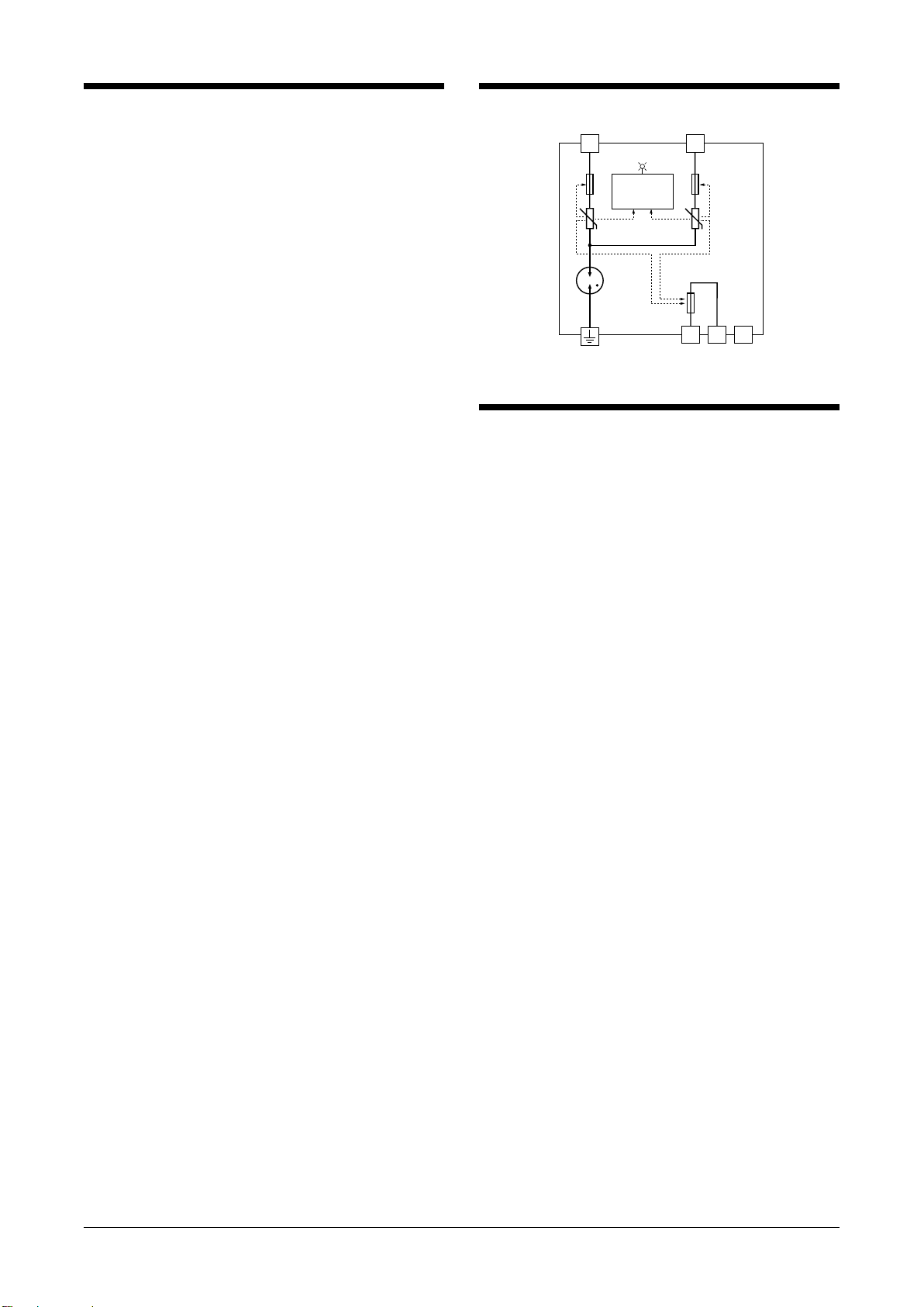
SCHEMATIC CIRCUITRY
L+
L–
A1 NCA0
ѳѳ
ѳ
Monitor LED
ѳ
: Thermal breaker
Note: Terminals A0 & A1 are available for ‘Alarm output’ code ‘A.’
Display
Circuit
U
U
INSTALLATION
■DIN RAIL MOUNTING
The MATPH is mounted on a 35-mm-wide DIN rail. Set the
MATPH so that its DIN rail adaptor is at the bottom. Posi-
tion the upper hook at the rear side of base on the DIN rail
and push in the lower.
When removing, push down the DIN rail adaptor utilizing a
minus screwdriver and pull.

MATPH
EM-8160 Rev.2 P. 3 / 5
MG CO., LTD. www.mgco.jp
5-2-55 Minamitsumori, Nishinari-ku, Osaka 557-0063 JAPAN
CONNECTION PROCEDURE
■INSTALLING CIRCUIT BREAKERS
This unit incorporates a thermal breaker which separates the discharge element from the power line upon detecting the in-
creased leakage current by the element’s gradual degradation.
However, in rare cases, when the unit is hit by an extremely strong lightning which exceeds the unit’s designed induced surge
capacity, the discharge element may be burned out and short-circuited at a burst without the thermal breaker being able to
separate it safely from the line.
Install a circuit breaker at the power source side of the surge protector as a backup protection. The example below shows a
photovoltaic system. Molded-case circuit breakers (MCCB), residual current circuit breaker (RCCB) or current limiting fuses
(slow-blow type only) can be used.
Blocking Diode
Distribution Board
Blocking Diode
10m min.
L+L−
Photovoltaic
Array
DC
AC
■CONNECTION DIAGRAM
■CIRCUIT BREAKER POSITION
If you want to use circuit breaker as SPD maintenance switch, insert a wiring MCCB for DC on SPD power side (diagram below).
Even when the output current of solar cell array is low, use 20 AT or more for wiring MCCB.
*2, *3
L+L−
*2, *3
*1
L+
L–
L+L−
Wiring MCCB
*1. When the wiring distance is longer than 10 m between the power conditioner and the surge protector in the switch gear, install near the power
conditioner.
*2. Cable length between the branch point and the earthing: 0.5 m or less recommended
*3. When the solar panel manufacturer requires earthing at negative line of DC side, do NOT use the earth terminal of the SPD but use the
L- terminal. If also, earthing at positive line is necessary, earth the L+ terminal.
Solar Cell
Array
Solar Cell
Array
Solar Cell
Array
Switch Gear Common Enclosure
Switch Gear
L+
L–
L+
L–
L+
L–
SPDSPD
SPD

MATPH
EM-8160 Rev.2 P. 4 / 5
MG CO., LTD. www.mgco.jp
5-2-55 Minamitsumori, Nishinari-ku, Osaka 557-0063 JAPAN
WIRING
■LEADWIRES
Conductor cross-section area: 5.5 mm2minimum for both
the power and the earth lines. However, a local industrial
standard requirement for wiring should take precedence.
■SOLDERLESS TERMINAL
Applicable ring tongue terminal without insulation sleeve
is as indicated below. Spade tongue terminal must conform
with the ring type size.
In order to ensure IP20 protection (IEC 60529) with a sol-
derless terminal, cover the terminal with a insulation cap
to prevent direct touching by a hand.
F
d : M5 use
B ≤ 12.5 mm
F ≥ 7.0 mm
(F ≥ 8.2 mm for sharing terminals)
T ≤ 1.8 mm
• Applicable Solderless Terminal Size
diameter d
BT
■TORQUE
Tighten the screw terminals securely. Maximum allowable
torque is of 2.5 N·m.
■WIRE LENGTH
Keep the wire length to the minimum for both the power
source side and the earth side. The wire length between the
branch point and the earth should ideally be less than 0.5
meters. Extra long wires should not be bundled in coils, but
be cut to the minimum required length.
EARTHING
■COMMON EARTHING WITH CROSS-OVER WIRE
Basically a common earthing with cross-wiring between the
MATPH and the protected device is recommended for ad-
equate protection. Earthing resistance should be less than
100 ohms. If the protected device has no earth terminal,
earth only the MATPH.
The earthing point should be close to the MATPH side as
shown below.
Cross-wiring
Protected
Device
G
+
-
L+
L
-
SPD
ALARM OUTPUT
Optional breack-contact relay output is available to alert
when the thermal breaker has separated the discharge ele-
ment from the power supply circuit.
If the alarm output should be transmitted remotely via out-
door cables, a surge protector for signal line is required.
Choose a circuit breaker with an alarm output. Configure a
logical addition sequence so that the alarm trips when both
or either of the MATPH or the breaker alarm trips.
■RELAY SPECIFICATIONS
Alarm output: The breack-contact relay trips when the ther-
mal breaker operates.
Rated load: 250V AC @50mA (resistive load)
24V DC @50mA (resistive load)
■CONNECTION
Terminal: Tension clamp
Applicable wire size: 0.13 to 1.5 mm2
Stripped length: 8 mm
CHECKING
■WIRING
• Make sure that wiring is done as instructed in the con-
nection diagram.
• Make sure that the earth terminal (G) is connected to the
metallic housing of protected equipment.
• Make sure that the earth terminal (G) is earthed to earth.

MATPH
EM-8160 Rev.2 P. 5 / 5
MG CO., LTD. www.mgco.jp
5-2-55 Minamitsumori, Nishinari-ku, Osaka 557-0063 JAPAN
MAINTENANCE
Even lightning in remote locations could induce surges
without our knowledge. Regular checking of the surge pro-
tector is important to find degradations in early stage, be-
fore and after the storm seasons, and whenever you experi-
ence a strong lightning storm.
DO NOT attempt checking or replacing the surge protector
during a thunder storm for safety.
Checking procedure is as explained below:
■CHECK EXTERIOR
If discoloration or deformation is observed, replace with a
new one immediately.
■CHECK MONITOR LED
Green LED turns on during normal operation, indicating
the surge protector is functioning properly. Turning off
means that the protector is in failure. Replace with a new
one immediately.
When the voltage between L+ and L- is low, the monitor
LED may be dark. In that case, check the LED with a insu-
lation tester (100 V DC to operational voltage). When the
polarity is opposite, change it.
EXTERNAL DIMENSIONS & TERMINAL ASSIGNMENT
Unit: mm (inch)
45°
(WIRE INSERTION ANGLE)
DIN RAIL
35mm wide
[3.4 (.13)]
60 (2.36)
80 (3.15)
ALARM OUTPUT
*
TERMINAL
50 (1.97)
15 (.59) 15 (.59)
L–
NCA1A0
L+
5–M5 SCREW
TERMINAL COVER
SPECIFICATION
*
Only for 'Alarm output' code 'A.'
MONITOR LED
98 (3.86)1 (.04)
80 (3.15)
15 (.59)
12.5 (.49)
Table of contents
Other MG Surge Protector manuals


