MG MAX User manual

EM-8175 Rev.7 P. 1 / 4
MAX
MG CO., LTD. www.mgco.jp
5-2-55 Minamitsumori, Nishinari-ku, Osaka 557-0063 JAPAN
LIGHTNING SURGE PROTECTOR FOR POWER SUPPLY USE
(5A; high discharge current capacity) MODEL MAX
INSTRUCTION MANUAL
BEFORE USE ....
Thank you for choosing us. Before use, please check contents of
the package you received as outlined below.
If you have any problems or questions with the product, please
contact our sales office or representatives.
■PACKAGE INCLUDES:
Lightning surge protector
(body + base socket + surge absorber element) ............... (1)
■MODEL NO.
Confirm that the model number described on the product is
exactly what you ordered.
■INSTRUCTION MANUAL
This manual describes necessary points of caution when you
use this product, including installation, connection and basic
maintenance procedures.
LIMITATION APPLICABLE TO M-RESTER
The M-Rester will protect electronics equipment from damage
caused by lightning by absorbing most of the surge voltages.
However, M-Rester may not be effective against certain
extremely high voltages caused by a direct or almost direct
hit by lightning.
M-Rester must be installed according to this installation /
instruction manual.
GENERAL
■ FUNCTION & FEATURES
• Designed specifically for AC power supplies up to 5 amps
• Discharge current capacity 10000 A
• Absorbs surges only without affecting instrumentation signal
• No power supply interruption even when the surge absorber
is broken
• Relay contact turns ON with surge absorber failure
• Surge absorber element replaceable without power interruption
■ SPECIFICATIONS
BETWEEN LINES LINE TO
GND
MAX-100 MAX-200
Discharge voltage (p-p)
190 V min. 410 V min. 640 V min.
Max. surge voltage* 350 V max. 700 V max. 800 V max.
Leakage current ≤ 1 mA
@150V DC
≤ 1 mA
@300V DC
≤ 1 mA
@300 V DC
Response time ≤0.01 µsec.
Discharge current 10000 A (8 / 20 µsec.)
Max. load current 5 A
Internal series resist. ≤ 0.5 Ω including return
*The maximum voltage that could pass through M-RESTER. Pro-
tected equipment must be able to withstand this voltage for a very
short time period.
POINTS OF CAUTION
■ ENVIRONMENT
• Indoor use.
• When heavy dust or metal particles are present in the atmos-
phere,install M-RESTER inside proper housing and ventilate it.
• Do not install the M-RESTER where it is subjected to continu-
ous vibration. Do not apply physical impact to the M-RESTER.
• Environmental temperature must be within -10 to +55°C (14
to 131°F) with relative humidity within 30 to 90% RH in order
to ensure adequate life span and operation.
■ WIRING
• Remove cables connected to the ground terminals (2 or 7) from
the base socket before insulation test. Otherwise the element
will start discharging at discharge voltage, which can cause
insulation failure. Be sure to return the cables as they were
after the testing is complete.
■ RATED CURRENT
• Be sure that the rated current of protected equipment does
not exceed the maximum load current specification of the
M-RESTER.
• Be sure to install a breaker which matches the current rating
at the power source side of the M-RESTER.
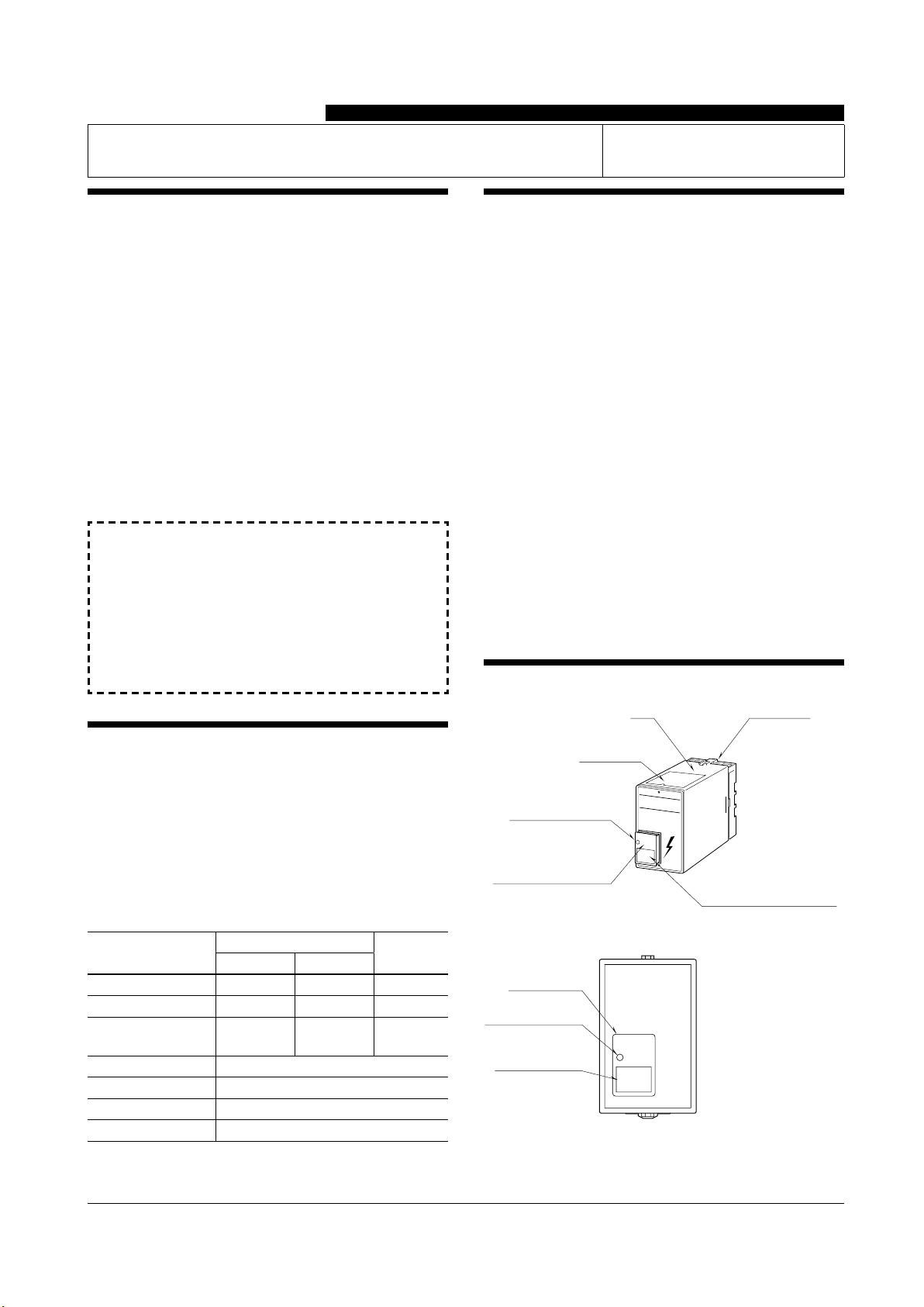
COMPONENT IDENTIFICATION
MAX
Model No. Label
for Surge Absorber Element
Body Base Socket
Specification
Label
Surge Absorber
Failure Indicator Hole
Surge Absorber Element
(model: MEL)
■FRONT PANEL CONFIGURATION
Model No. Label
for Surge Absorber
Element
Surge Absorber
Failure Indicator Hole
Surge Absorber
Element
Model suffix code of the surge absorber element (model: MEL)
changes according to the line voltage. Use correct model and
suffix code when ordering.

EM-8175 Rev.7 P. 2 / 4
MAX
MG CO., LTD. www.mgco.jp
5-2-55 Minamitsumori, Nishinari-ku, Osaka 557-0063 JAPAN
INSTALLATION
Detach the yellow clamps located at the top and bottom of the
unit for separating the body from the base socket.
■ DIN RAIL MOUNTING
Set the base socket so that its DIN rail adapter is at the bottom.
Hung the upper hook at the rear side of base socket on the DIN
rail and push in the lower. When removing the socket, push
down the DIN rail adapter utilizing screwdriver (–) and pull.
Clamp
(top & bottom)
DIN Rail
35mm wide
Spring Loaded
DIN Rail Adaptor
Shape and size of the base socket
are slightly different with various
socket types.
■ WALL MOUNTING
Refer to the next drawings.
■ GROUNDING
A cross-over wire between M-RESTER and ground or metallic

EM-8175 Rev.7 P. 3 / 4
MAX
MG CO., LTD. www.mgco.jp
5-2-55 Minamitsumori, Nishinari-ku, Osaka 557-0063 JAPAN
EXTERNAL DIMENSIONS unit: mm (inch)
3456
2187
80 (3.15)
50 (1.97) 103 (4.06)
123 (4.84)7 (.28) [3.3 (.13)]
80 (3.15)
20
(.79)
35.4 (1.39)
40 (1.57)
50 (1.97)
7.8 (.31)
CLAMP
(top & bottom)
DIN RAIL
35mm wide
SURGE ABSORBER
ELEMENT (model: MEL)
2–4.5 (.18) dia.
MTG HOLE
15 (.59) deep
8–M3.5
SCREW
•When mounting, no extra space is needed between units.
TERMINAL CONNECTIONS
Connect the unit as in the diagram below.
Be sure to cross-wire between the Ground terminal (2 or 7) and
metallic housing of the protected equipment. (100 Ω max.)
4
5
3
6
ALARM OUTPUT
PROTECTED
EQUIPMENT
(load side)
1
8
2
7
POWER
SOURCE
(surge side)
BREAKER
Be sure to install
the Breaker.
B
■ GROUNDING
M-RESTER PROTECTED
EQUIPMENT
G
G
CROSSOVER WIRE
GROUNDING
(100 Ωor less)
A crossover wire between M-RESTER ground and the ground or
metallic housing of the equipment is required for protection.
SURGE ABSORBER ELEMENT
When a strong lightning surge exceeding discharge current
capacity of lightning arrester enters to power supply cables,
conventional lightning arrester cuts off the supply line with its
fuse blown in order to prevent ignition.
The model MAX is designed to separate its surge absorber element
(model: MEL) from power supply lines when there is anomaly
with the element. It ensures no interruption of power supply
and thus the plant itself.
The MEL indicates its failure with contact output (ON) and front
indicator (turns white). In such condition, maximum surge volt-
age may be up to 800 V. Replacing the MEL as soon as possible
is recommended.
■ REPLACING THE MEL
Replacing the MEL is very simple without interruption of power
supply.
Pull the MEL off from the main body, and replace with a new one.
Insert it to the connector. (See the figure below.)
The replacement MEL is available with following model No.
MEL-100: for 100V/110V/120V AC power
MEL-200: for 200V/220V/240V AC power
We recommend that you keep spare MELs so that you can replace
them when necessary.
MEL Connector
MEL

EM-8175 Rev.7 P. 4 / 4
MAX
MG CO., LTD. www.mgco.jp
5-2-55 Minamitsumori, Nishinari-ku, Osaka 557-0063 JAPAN
MAINTENANCE
Check M-RESTER periodically. Many cases of lightning are
ignored, and even lightning at a far distance often causes in-
ductive surges.
We recommend that you check your M-RESTER about twice a
year, before and after the rainy season. Check whenever you
experience a strong lightning occurrence.
Checking procedure is explained in the following:
■ CHECKING
WIRING
• Make sure that wiring is done as instructed in the connection
diagram.
• Make sure that the Ground terminal (2 or 7) is connected to
the metallic housing of protected equipment.
• Make sure that the Ground terminal (2 or 7) is grounded to earth.
ALARM CONTACT AND INDICATOR
• M-RESTER is designed to protect the equipment even when
subjected to a lightning surge exceeding its discharge cur-
rent capacity to certain extent. However, in such a case, the
insulation of its discharge element may fail. When it hap-
pens, a relay contact turns ON and the indicator on the front
panel of M-RESTER turns white.
Replace the surge absorber element, model MEL according
to the procedure described in the left.
DISCHARGE FUNCTION
Remove the MEL and test its discharge capability as follows:
• Check resistance across the terminals (B) – (L) (infinite
standard).
• Check that discharging occurs across the same terminals with a
1000V DC megger. (Indicator of the megger reaches over-scale.)
L
B
MEL SIDE VIEW
LEAKAGE CURRENT (between lines)
Return the MEL and apply supply voltage across the terminals
(1) – (8) with no load, and measure current at the terminal (1).
(≤ 1 mA standard)
• If any of the above tests shows negative, replace the MEL after
that you confirm that the main body unit functions properly
with the following tests. If the following tests show negative,
replace the whole M-RESTER unit.
MAIN BODY UNIT TEST
• Remove the MEL and all wiring and check resistance across
the following terminals. (≤ 0.5 Ω standard)
Terminals (1) – (4), (5) – (8)
• With the MEL and all wiring detached,check resistance across
the following terminals. (infinite standard)
Terminals (1) – (8), (1) – (7), (7) – (8)
• Check that discharging occurs across the same terminals with a
1000V DC megger. (Indicator of the megger reaches over-scale.)
This manual suits for next models
2
Other MG Surge Protector manuals
Popular Surge Protector manuals by other brands

CyberPower
CyberPower HT706UC user manual

TrickleStar
TrickleStar SensorClick TS1802MS Quick start guide & instructions

Joslyn
Joslyn PanelTrack TK-PK025D-24VDC Installation, operation and maintenance manual

Rice Lake
Rice Lake TP232 installation guide

9dot
9dot C-POE manual

ABB
ABB RELION RET670 Product guide