manuals.online logo
Brands
  1. Home
  2. •
  3. Brands
  4. •
  5. MG
  6. •
  7. Transducer
  8. •
  9. MG MUWT User manual

MG MUWT User manual

BEFORE USE ....
Thank you for choosing us. Before use, please check con-
tents of the package you received as outlined below.
If you have any problems or questions with the product,
please contact our sales office or representatives.
■PACKAGE INCLUDES:
Signal conditioner
(body + base socket + CT protector) ...................................(1)
■MODEL NO.
Confirm Model No. marking on the product to be exactly
what you ordered.
■INSTRUCTION MANUAL
This manual describes necessary points of caution when
you use this product, including installation, connection and
basic maintenance procedures.
POINTS OF CAUTION
■POWER INPUT RATING & OPERATIONAL RANGE
• Locate the power input rating marked on the product and
confirm its operational range as indicated below:
AC power: Rating ±10%, 50/60 ±2 Hz, approx. 2VA
DC power: Rating ±10%, approx. 2W
or 85 – 150V, approx. 2W for 110V rating
■GENERAL PRECAUTIONS
• Before you remove the unit from its base socket or mount
it, turn off the power supply and input signal for safety.
■CT PROTECTOR
• Temperature of the CT Protector may rise if the signal
conditioner body is left unplugged from the base socket.
Be careful not to get burned when you need to touch it.
■ENVIRONMENT
• Indoor use.
• When heavy dust or metal particles are present in the
air, install the unit inside proper housing with sufficient
ventilation.
• Do not install the unit where it is subjected to continuous
vibration. Do not subject the unit to physical impact.
• Environmental temperature must be within -5 to +60°C
(23 to 140°F) with relative humidity within 30 to 90% RH
in order to ensure adequate life span and operation.
■WIRING
• Do not install cables close to noise sources (relay drive
cable, high frequency line, etc.).
• Do not bind these cables together with those in which
noises are present. Do not install them in the same duct.
■AND ....
• The unit is designed to function as soon as power is sup-
plied, however, a warm up for 10 minutes is required for
satisfying complete performance described in the data
sheet.
COMPONENT IDENTIFICATION
Body Base Socket
Aux. Specifications
Front Cover
Specifications
Connection Diagram
(side)
CT Protector
■HOW TO OPEN THE FRONT COVER:
Hang your finger on the hook at the top of the front cover
and pull.
The shape of base socket may be different
for some models.
■FRONT PANEL CONFIGURATIONS
S5
S4
S3
S2
S1 a4 × 10– 4
a3 × 10– 3
a2 × 10– 2
a1 × 10– 1
10– (a5)
Span Adj. (DC output)
Zero Adj. (DC output)
Front Cover (open)
Pulse
Rate
WATT TRANSDUCER
(with pulse output) MODEL MUWT
EM-1926 Rev.2 P. 1 / 4
MG CO., LTD. www.mgco.jp
5-2-55 Minamitsumori, Nishinari-ku, Osaka 557-0063 JAPAN
INSTRUCTION MANUAL
INSTALLATION
Detach the yellow clamps located at the top and bottom of
the unit for separate the body from the base socket.
Clamp
(top & bottom)
DIN Rail
35mm wide
Spring Loaded
DIN Rail Adaptor
Shape and size of the base socket
are slightly different with various
socket types.
■DIN RAIL MOUNTING
Set the base socket so that its
DIN rail adaptor is at the bot-
tom. Hang the upper hook at
the rear side of base socket on
the DIN rail and push in the
lower. When removing the
socket, push down the DIN
rail adaptor utilizing a minus
screwdriver and pull.
■WALL MOUNTING
Refer to “EXTERNAL DI-
MENSIONS.”
TERMINAL CONNECTIONS
Connect the unit as in the diagram below or refer to the connection diagram on the side of the unit.
Attach the CT Protector together with input wiring to the input screw terminals.
■EXTERNAL DIMENSIONS unit: mm (inch)
80 (3.15)
72 (2.83) 109 (4.29)
139 (5.47) [3.3 (.13)]
80 (3.15)
20
(.79)
60 (2.36)
72 (2.83)
7.8 (.31)
CLAMP
(top & bottom)
DIN RAIL
35mm wide
2–4.5 (.18) dia.
MTG HOLE
25 (.98) deep
14–M3.5
SCREW
•When mounting, no extra space is needed between units.
12
56
14
1
10
4
3
7
8
CT PROTECTOR
(model: CTM)
20
(.79)
12
1 MUWT-2
2 MUWT-1, 31
Positions of CTM
9
15 11
2
MUWT
EM-1926 Rev.2 P. 2 / 4
MG CO., LTD. www.mgco.jp
5-2-55 Minamitsumori, Nishinari-ku, Osaka 557-0063 JAPAN
■CONNECTION DIAGRAM
+
–
12
44
12
• AC Powered
LOAD
• DC Powered
LOAD
Spark Quenching
Diode
Varistor or Spark
Quenching Circuit
Relay or
Counter Coil
Relay or
Counter Coil
U
4
12
■ Open Collector
Pulse Output Connection Examples
■Power Photo MOSFET Relay
LOAD
+
–
123
SOURCE
P2V
P1U
v
u
FUSE VT
Vv
P3
Uu
k
l
CT
L
K
1L
1S
3L
3S
k
l
L
K
6
5
8
12
4
9
11
2
15
PULSE OUTPUT
+
–
10
1
DC OUTPUT
■
3-PHASE/3-WIRE ■SINGLE-PHASE/2-WIRE
LOAD
12
SOURCE
P2V
P1U
v
u
FUSE VT
k
l
CT
L
K
1L
1S
+
–
6
8
12
4
9
15
PULSE OUTPUT
■
SINGLE-PHASE/3-WIRE
LOAD
1N2
SOURCE
P0V
P1U
v
u
FUSE VT
Vv
P2
Uu
k
l
CT
L
K
1L
1S
2L
2S
k
l
L
K
+
–
6
5
8
12
4
9
11
2
15
PULSE OUTPUT
7
14
U(+)
V(–)
POWER
**
7
14
U(+)
V(–)
POWER
**
+
–
10
1
DC OUTPUT
+
–
10
1
DC OUTPUT
7
14
U(+)
V(–)
POWER
**
*
*
*CT Protector (model: CTM) attached to these terminals.
*
*CT Protector (model: CTM) attached to these terminals.
*
*
*CT Protector (model: CTM) attached to these terminals.
**The transducer can be powered from the input voltage
when the voltage is sufficiently stable and meets
other supply voltage requirements.
MUWT
EM-1926 Rev.2 P. 3 / 4
MG CO., LTD. www.mgco.jp
5-2-55 Minamitsumori, Nishinari-ku, Osaka 557-0063 JAPAN
CHECKING
1) Terminal wiring: Check that all cables are correctly con-
nected according to the connection diagram.
2) Power input voltage: Check voltage across the terminal
7 – 14 with a multimeter.
3) Input: Calculate the calibration range and check that the
result is within the usable range.
Calibration Range [W] = Measuring Wattage
(VT Ratio) × (CT Ratio)
4) DC output: Check that the load resistance meets the de-
scribed specifications.
5) Integrating pulse output: Check the load connected to
the pulse output:
Open collector: 35V DC @100mA
Power photo MOSFET relay: 120V AC/DC @100mA
ADJUSTMENT PROCEDURE
This unit is calibrated at the factory to meet the ordered
specifications, therefore you usually do not need any cali-
bration.
For matching the signal to a receiving instrument or in case
of regular calibration, adjust the output as explained in the
following.
■HOW TO CALIBRATE THE DC OUTPUT SIGNAL
Use a signal source and measuring instruments of sufficient
accuracy level. Turn the power supply on and warm up for
more than 10 minutes.
1) ZERO: Apply 0% input and adjust output to 0%.
2) SPAN: Apply 100% input and adjust output to 100%.
3) Check ZERO adjustment again with 0% input.
4) When ZERO value is changed, repeat the above proce-
dure 1) – 3).
■HOW TO SET THE PULSE UNIT
The switches S1 through S5, VT and CT ratios, and the
transducer’s calibration input range all determine the rela-
tive value of one pulse, i.e. the number of kWh per pulse.
VT Ratio × CT Ratio × Calibration Range [kW]
2.777 Hz × 3600 [s] × 10 × Pulse Unit [kWh/pulse]
= 0.XXXX × 10–X
= 0. [a1] [a2] [a3] [a4] × 10–[a5]
a1 though a4: integer, 1 though 9
a5: integer, 0 through 6
[example] VT 3300V / 110V, CT 250A / 5A, Pulse Unit 10
[kWh/pulse], Calibration Range 1000 [W]
3300 / 110 × 250 / 5 × 1 [kW]
2.777 Hz × 3600 [s] × 10 × 10 [kWh/pulse]
= 0.1500 × 10⁻²
S1 = 1, S2 = 5, S3 = 0, S4 = 0, S5 = 2
MAINTENANCE
Regular calibration procedure is explained below:
■CALIBRATION
Warm up the unit for at least 10 minutes. Apply 0%, 25%,
50%, 75% and 100% input signal. Check that the output
signal for the respective input signal remains within accu-
racy described in the data sheet. When the output is out of
tolerance, recalibrate the unit according to the “ADJUST-
MENT PROCEDURE” explained earlier.
LIGHTNING SURGE PROTECTION
We offer a series of lightning surge protector for protec-
tion against induced lightning surges. Please contact us to
choose appropriate models.
MUWT
EM-1926 Rev.2 P. 4 / 4
MG CO., LTD. www.mgco.jp
5-2-55 Minamitsumori, Nishinari-ku, Osaka 557-0063 JAPAN

Other MG Transducer manuals

MG LPAUN User manual

MG

MG LPAUN User manual

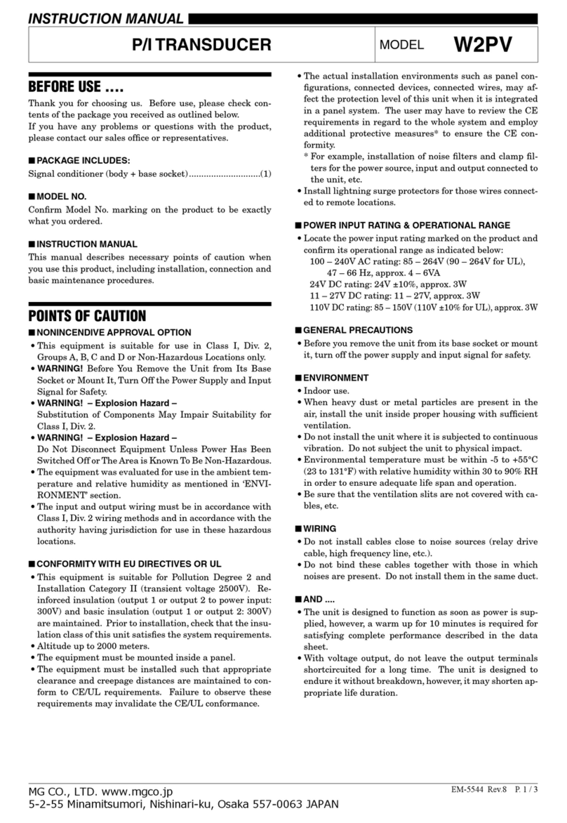
MG W2PV User manual

MG

MG W2PV User manual

MG LTRPN User manual

MG

MG LTRPN User manual

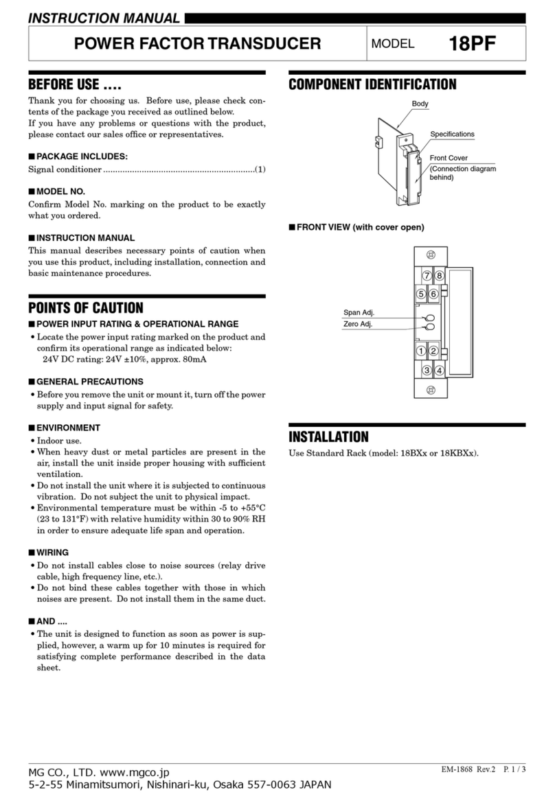
MG 18PF User manual

MG

MG 18PF User manual

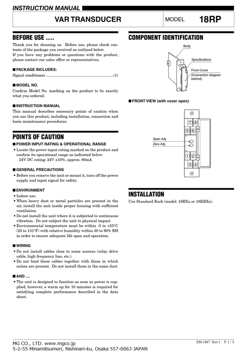
MG 18RP User manual

MG

MG 18RP User manual

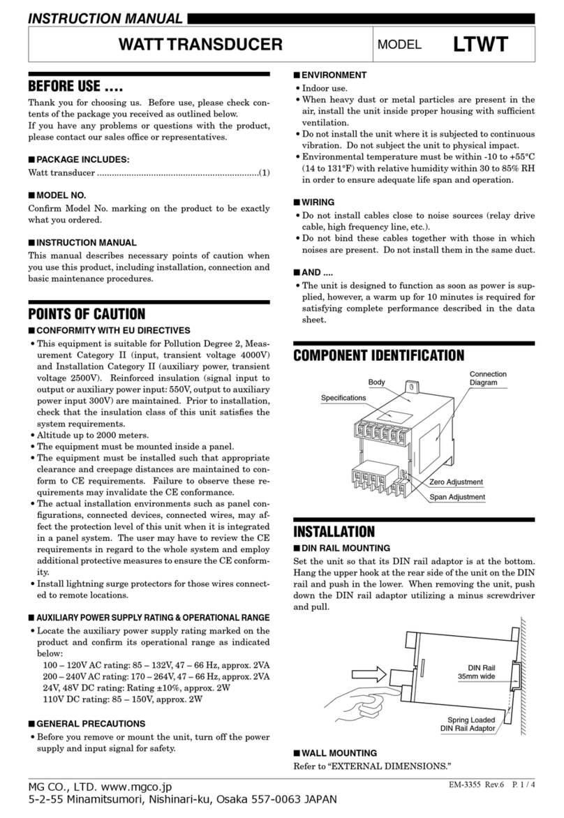
MG LTWT User manual

MG

MG LTWT User manual

MG L2PNA User manual

MG

MG L2PNA User manual

MG 17CE User manual

MG

MG 17CE User manual

MG 18WT User manual

MG

MG 18WT User manual

Popular Transducer manuals by other brands

Magtrol TM Series user manual

Magtrol

Magtrol TM Series user manual

Mod-tronic APD 1500 Series quick start guide

Mod-tronic

Mod-tronic APD 1500 Series quick start guide

Lumel P41 User Manual & Quick Start

Lumel

Lumel P41 User Manual & Quick Start

S+S Regeltechnik THERMASGARD ALTM Operating Instructions, Mounting & Installation

S+S Regeltechnik

S+S Regeltechnik THERMASGARD ALTM Operating Instructions, Mounting & Installation

CEMB TV22 Use and maintenance instruction manual

CEMB

CEMB TV22 Use and maintenance instruction manual

Guitammer ButtKicker Advancer owner's manual

Guitammer

Guitammer ButtKicker Advancer owner's manual

Ashcroft IXLdp instruction sheet

Ashcroft

Ashcroft IXLdp instruction sheet

Lumel P18-0 user manual

Lumel

Lumel P18-0 user manual

KYOWA DTC-A instruction manual

KYOWA

KYOWA DTC-A instruction manual

NK TECHNOLOGIES DT Series instructions

NK TECHNOLOGIES

NK TECHNOLOGIES DT Series instructions

Airmar Technology Corporation Tilted Element DT800V-0 Owner's guide & installation instructions

Airmar Technology Corporation

Airmar Technology Corporation Tilted Element DT800V-0 Owner's guide & installation instructions

HBM TJ1-S6 installation manual

HBM

HBM TJ1-S6 installation manual

M-system LTHZ instruction manual

M-system

M-system LTHZ instruction manual

RDP Group D5 Series Technical manual

RDP Group

RDP Group D5 Series Technical manual

LEM ITZ 2000-SBPR FLEX ULTRASTAB manual

LEM

LEM ITZ 2000-SBPR FLEX ULTRASTAB manual

WIKA F1106 operating instructions

WIKA

WIKA F1106 operating instructions

Simrad 120-25 -  REV B datasheet

Simrad

Simrad 120-25 - REV B datasheet

Electro-Voice 3-Inch High Frequency Neodymium Transducer... Technical specifications

Electro-Voice

Electro-Voice 3-Inch High Frequency Neodymium Transducer... Technical specifications

manuals.online logo
manuals.online logoBrands
  • About & Mission
  • Contact us
  • Privacy Policy
  • Terms and Conditions

Copyright 2025 Manuals.Online. All Rights Reserved.